Advertisement
Quick Links
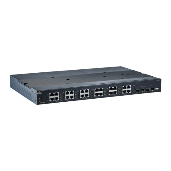
EX75900 Series Hardened Managed PoE Ethernet Switch
Installation Guide
1
Unpacking
Unpack the items. Your package should include:
One EX75900 Series switch
➢
➢
On RJ-45 console cable
➢
Rack-mounting hardware brackets
If items are missing or damaged, notify your EtherWAN representative.
Keep the carton and packing material.
Download the full manual at:
https://www.etherwan.com
2
What Else You Need
➢
Appropriate cables for data ports. To prevent damage to the switch
from electrical surges, it is recommended to use STP (Shielded
twisted pair) cabling.
➢
Personal computer or laptop
3
Select a Location
➢
Desktop installations: Mount on a flat table or shelf surface.
Rack installations: Use a 19-inch (48.3-centimeter) EIA standard
➢
equipment rack that is grounded and physically secure.
EX75900
03/19/2020
Identify a power source within 6 feet (1.8 meters).
➢
➢
Choose a dry area with ambient temperature between -40 and 75ºC
(-40 and 167ºF).
➢
Keep away from heat sources, sunlight, warm air exhausts, hot-air
vents, and heaters.
Be sure there is adequate airflow.
➢
4
Connect to the Data Ports
Depending on the model, your switch can have the following ports:
➢
24 10/100/1000Base-TX PoE ports
➢
4 1G SFP or 4 1G/10G SFP slots
10/100/1000Base-TX Ports
Ports that support Power over Ethernet provide power to networked
devices such as IP Phones, Wireless LAN Access Points, and IP security
cameras. Total power budget is 720 Watts, 60 Watts per port.
1G/10G SFP Slots
SFP transceivers can be installed directly into SFP slots. Ensure that the
same type of transceiver is used at both ends of the link and that the
correct type of fiber cable is used.
Copyright 2020 EtherWAN Systems, Inc.
All Rights Reserved
5
Apply DC Power
The switch has two terminal block power inputs. Only one power input is
required to operate the switch. However, redundant power supply
functionality is supported. Input voltage is 52-57 VDC.
Relay Output Alarm
The switch provides relay output contacts for signaling of a user-defined
power or port failure. The relay output can be connected to an alarm
signaling device. Current is 0.5A at 48VDC.
Power-Up Sequence
When you apply DC power:
All Link/ACT LEDs blink momentarily.
➢
The Power LED goes ON.
➢
Booting ⮕ The Alarm LED goes ON
➢
System ready ⮕ The Alarm LED goes off
➢
6
Front Panel LEDs
LED
Color
Status
Green
ON = power on
Power
OFF = power off
1 & 2
Green
ON = Valid network connection is
Link/ACT
established
Flashing = Port sending or receiving data
Amber
ON = Powered Device is connected
PoE
Off = Powered Device is disconnected
Red
Link down or power down
Alarm
Page 1
W70G-EX75900Q2
Advertisement

Related Manuals for EtherWAN EX75900 Series


Summary of Contents for EtherWAN EX75900 Series
- Page 1 Rack-mounting hardware brackets vents, and heaters. The switch provides relay output contacts for signaling of a user-defined If items are missing or damaged, notify your EtherWAN representative. Be sure there is adequate airflow. ➢ power or port failure. The relay output can be connected to an alarm Keep the carton and packing material.
- Page 2 192.168.1.10 in the address bar. Enter the default login ID: root (no password) and click “Login.” For repair or maintenance needs, contact EtherWAN directly. (A) Elevated Operating Ambient - If installed in a closed or multi-unit rack assembly, the operating ambient temperature of the rack Informations de câblage d'alimentation:...
Need help?
Do you have a question about the EX75900 Series and is the answer not in the manual?
Questions and answers