Table of Contents
Advertisement
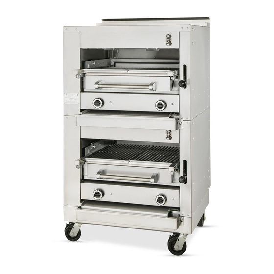
GAS FIRED BROILERS
E36W36
E43W36
E136W36
EV136W36
EC36W36
WC43W36
E136C36
E136C45
with optional searing plate (-SHB)
This manual is prepared for the use of Service Technicians
and should not be used by those not properly qualified. This
manual is not intended to be all encompassing. You should
read, in its entirety, the repair procedure you wish to per-
form to determine if you have the necessary tools,
instruments, and skills required to perform the procedure.
THE MONTAGUE COMPANY
1830 Stearman Avenue • P.O. BOX 4954 • HAYWARD,CA 94540-4954 •TEL: 510/785-8822 • FAX: 510/785-3342
E236W36
E243W36
EC36
EC45
EV136C36
EV136C45
W136XC36
W136XC45
RETAIN THIS MANUAL FOR FUTURE REFERENCE.
DESTINATION COUNTRIES: AUSTRALIA, NEW ZEALAND
NOTICE:
INSTRUCTIONAL
MANUAL
www.montaguecompany.com
Advertisement
Table of Contents

Related Manuals for MONTAGUE E36W36


Summary of Contents for MONTAGUE E36W36
- Page 1 RETAIN THIS MANUAL FOR FUTURE REFERENCE. DESTINATION COUNTRIES: AUSTRALIA, NEW ZEALAND THE MONTAGUE COMPANY www.montaguecompany.com 1830 Stearman Avenue • P.O. BOX 4954 • HAYWARD,CA 94540-4954 •TEL: 510/785-8822 • FAX: 510/785-3342...
-
Page 2: Important For Your Safety
IMPORTANT FOR YOUR SAFETY THE INSTALLATION INSTRUCTIONS CONTAINED HEREIN ARE FOR THE USE OF QUALIFIED INSTALLATION AND SERVICE PERSONNEL ONLY. INSTALLATION OR SERVICE BY OTHER THAN QUALIFIED PERSONNEL MAY RESULT IN DAMAGE TO THE UNIT AND/OR INJURY TO THE OPERATOR. IF YOU SMELL GAS 1. -
Page 3: Table Of Contents
………. 22 GENERAL ………. 4 36W36 & 43W36 PARTS LIST ………. 23 MODELS ………. 4 Montague E136 Series Heavy Duty Range Parts ………. 24 DATA PLATE LOCATION ………. 4 List SERIAL NUMBER LOCATION ………. 4 PARTS REMOVAL AND REPLACEMENT PRO- ………. -
Page 4: Introduction
Ovens are CATEGORY: covered in separate manuals. This manual only covers the broiler. SUPPLY PRESSURE: mbar Montague gas broilers are produced with the best GAS: SET PRESS: mbar possible material and workmanship. Proper installation is essential for safe, efficient, trouble- ELECTRICAL free operation. -
Page 5: Specifications
SPECIFICATIONS Table A: Heat Input MODEL No. Burners Natural Gas Propane Gas TOTAL (broiler/oven) MJ/h MJ/h MJ/h E36W36 2 / 0 44.3 ea. 44.3 ea. 88.6 E43W36 3 / 0 44.3 ea. 44.3 ea. 132.9 E136W36 2 / 1 44.3 / 42.2 ea. -
Page 6: Installation
INSTALLATION THIS APPLIANCE, WHEN INSTALLED, MUST BE ELECTRICALLY GROUNDED IN ACCORDANCE WITH LOCAL CODES. THIS APPLIANCE MUST BE INSTALLED WITH THE REQUIREMENTS OF AS5601 / AG601, LOCAL AUTHORITY, GAS, ELECTRICITY AND ANY OTHER RELEVANT STATUTORY REGULATIONS. CAUTION: Provision must be made to assure adequate air supply to unit for proper burner operation. -
Page 7: Electrical Connection
OVERALL DIMENSIONS (in millimetres): Model Height Width Depth E36W36 1816 E43W36 1816 1143 E(V)136W36 1816... -
Page 8: Ceramic Radiants
Setting in Place Figure 3. Ceramic Radiants Model Nos. E36W36, E43W36, E136W36 and EV136W36. 1. Insert ceramic end pieces at front and rear of the burner frame. Four (4) are required... -
Page 9: Floor Mounted Ranges
All fixed (non-mobile) appliances MUST be fitted Floor Mounted Ranges with a manual gas cook upstream of the appliance to provide a means of isolation for 1. Place the first unit in the exact position it will servicing and cleaning. A union or similar means occupy in the battery. -
Page 10: Gas Pressure Regulator
WARNING! Test all pipe joints for leaks before operating broiler. This includes all gas connections that may have loosened during shipment. Use a rich soap solution (or other accepted leak tester) around all pipe connections and all other joints. Do not use an open flame. Absolutely no leakage should occur, otherwise there is a danger of fire or explosion depending upon conditions. -
Page 11: Adjustment Procedure
Adjustment Procedure WARNING! 6. Connect a manometer to the pressure tap DO NOT ALLOW UNTRAINED PERSONNEL provided on the broiler unit gas piping manifold, TO MAINTAIN OR SERVICE THE GAS Figure 6. Turn all gas taps to the full on ―O‖ PRESSURE REGULATOR. -
Page 12: Pilot Initial Adjustment
PILOT INITIAL ADJUSTMENT 1. Lift off the Venturi cover to access the air shutter for each main burner. Each burner has a separate pilot burner. The pilot flame is adjusted through access holes in 2. Turn on the main burner control valve for the valve control panel, Figure 7. - Page 13 OVEN MINIMUM FLAME SETTING This is the flame that must be maintained on the burner when the oven has come up to the temperature set on the dial. Enough gas must be bypassed by the control to keep the entire burner lit.
- Page 14 THERMOSTAT CALIBRATION CHECK The calibration of this thermostat should not be changed until considerable experience with cooking results has definitely proved that the thermostat is not maintaining the proper temperature. The recalibration should not be made until the bypass (minimum burner) flame has been properly adjusted.
-
Page 15: Operation
OPERATION BURNER CONTROL: Used to turn the main GENERAL burner and pilot gas on or off. One control for each burner. This appliance has been classified as commercial cooking equipment and must be GRID HEIGHT: The grid is set to the desired operated by qualified and/or professional cooking height by depressing the ball and operating personnel. -
Page 16: Shutdown
Shutdown, Broiler Preheat, and Grid Height Adjustment 1. Standby: To turn off, rotate main burner valve handles clockwise to the ignition position. 2. Complete: To shut the burner and pilot off, turn the dial to the ―●‖ symbol and the safety device will disengage within 60 seconds. - Page 17 OVENS The temperature is automatically controlled by the thermostat so that satisfactory cooking can be repeated. For the best performance, the following instruction should be followed: GRID SHELVES—There are three shelf positions. The shelf position is governed by the size of the product to be cooked.
-
Page 18: General Maintenance
GENERAL MAINTENANCE PAINTED SURFACES GENERAL CLEANING Exterior WARNING! THE BROILER AND ITS PARTS ARE HOT. Allow the broiler to cool down before cleaning USE CARE WHEN OPERATING, CLEANING exterior surfaces. Painted surface should be OR SERVICING THE UNIT. cleaned using a mild soap and warm water solution on a sponge or soft cloth. -
Page 19: Ventilation
To remove heat tint: WARNING! If not installed, operated, and Darkened areas sometimes appear on maintained in accordance with the stainless steel surfaces where the area has manufacturer’s instructions, this product been subjected to excessive heat. These could expose you to substances in fuel or darkened areas are caused by thickening of the in fuel combustion which can cause death protective surface of the stainless steel and are... -
Page 20: C36 & C45 Exploded View
C36 & C45 EXPLODED VIEW... -
Page 21: C36 & C45 Parts List
ITEM PART NUMBERS DESCRIPTION 236W36 243W36 2033-8 2033-8 KNOB, BLACK BALL 3504-1 3504-1 HANDLE, SLEEVE 1600-4 1600-4 GRID IRON, RIGHT 1602-0 GRID IRON, CENTER 1601-2 1601-2 GRID IRON, LEFT 43476-0 43476-0 HANDLE, VALVE 11611-4 11611-4 CERAMIC, LARGE CERAMIC KIT (10 ea. 11611-4 Large Ceramics, 4 ea. 11614-9 Ceramic 28387-8 28387-8 Insulators) -
Page 23: 36W36 & 43W36 Parts List
ITEM PART NUMBERS DESCRIPTION 36W36 43W36 2033-8 2033-8 KNOB, BLACK BALL 3504-1 3504-1 SLEEVE 1601-2 1601-2 GRID IRON, RIGHT 1602-0 GRID IRON, CENTER 1601-2 1601-2 GRID IRON, LEFT 43476-0 43476-0 HANDLE, VALVE 11611-4 11611-4 CERAMIC, LARGE CERAMIC KIT (10 ea. 11611-4 Large Ceramics, 4 ea. 1 1614-9 Ceramic 28387-8 28387-8 Insulators) - Page 26 WIRE DIAGRAM EV136-AUSTRALIA 240V 50HZ, 1PH ITEM DESCRIPTION SWITCH, FAN MOTOR WIRE—TYPE: SIZE 18 GA, 200°C TERMINAL BLOCK SWITCH, DOOR REPLACEMENT WIRES MUST BE OF SAME TYPE OR EQUIVALENT AS ORIGINAL. 02-13-09 REV A 46527-5...
-
Page 27: Parts Removal And Replacement Pro
PARTS REMOVAL AND REPLACEMENT PROCEDURES Perform the following procedures to remove COVERS AND PANELS and replace parts. To eliminate mistakes when ordering parts, always provide the following CAUTION: Turn off the gas supply at the information: manual shutoff valve that is next to the broiler before attempting to loosen any gas Model Number connections. -
Page 28: Drip Deflector
DRIP DEFLECTOR DRIP TRAY AND HORIZONTAL GREASE CONTAINER The drip deflector is located below the grid frame and is angled toward the back of the The drip tray is located below the drip deflector. broiler. Grease dripping onto the drip deflector Grease dripping onto the drip deflector runs off runs off the back edge to the drip tray, then the back edge to the drip tray then flows... -
Page 29: Pilot Assembly And Injector
PILOT ASSEMBLY AND INJECTOR The pilot assembly is located adjacent to each burner. The connection for the pilot assembly is accessed through the opening of the broiler compartment. CAUTION: Turn off the gas supply at the manual shutoff valve that is next to the broiler before attempting to loosen any gas connections. -
Page 30: Main Burner
MAIN BURNERS 9. Reassemble by reversing procedure. WARNING! The connection for the burners is accessed by All gas joints disturbed during servicing removing the Venturi cover. The burners are must be checked for leaks. Check with a accessed by removing the grids and carriage. soap and water solution (bubbles). -
Page 31: Burner Valve Removal/Replacement
7. Light pilot (clockwise) onto the threaded stud. Chrome Sleeve 8. Reinstall the control panel cover and control valve knobs. 1. Turn off the burners. 9. Turn burner valve full on and check that burner 2. Allow the broiler to cool to room temperature. is properly lit. -
Page 32: Carriage Position Handle
Compression Spring Gear with Bracket 1. Turn off the burners. 1. Turn off the burners. 2. Allow the broiler to cool to room tempera- 2. Allow the broiler to cool to room ture. temperature. 3. Remove the black ball knob by unscrewing 3. -
Page 33: Service And Adjustment Procedures
SERVICE AND ADJUSTMENT PROCEDURES Regular maintenance by a competent person is recommended to ensure the continued safe and efficient performance of the appliance. Should service be required, kindly contact your dealer for assistance. Alternately, please contact us at the following address: HAVERICK MEATS PO BOX 13, 13-15 GREEN STREET BANKSMEADOW, NSW 2019... -
Page 34: Ment Procedure Pilot Burner Cleaning And Adjust
PILOT BURNER CLEANING AND INSPECTION CLEANING BURNER VENTURI PROCEDURE 1. Remove top panel. 1. Light the pilot burner as described in the 2. Remove right control panel. Installation and Operation section of this 3. Disconnect injector fitting and remove. manual. 4. -
Page 35: Carriage Tension Spring Adjustment
Listen for the flame failure valve clicking closed. This action must occur Model Nos. E36W36 and E43W36: within 60 seconds of extinguishing the pilot. Through lower compartment. Model Nos. E136W36 and EV136W36: Behind valve panel. -
Page 36: Oven Pilot Burner
OVEN MINIMUM FLAME SETTING This is the flame that must be maintained on the burner when the oven has come up to the temperature set on the dial. Enough gas must be bypassed by the control to keep the entire burner lit. -
Page 37: Operational Difficulties & Probable
THERMOSTAT CALIBRATION CHECK The calibration of this thermostat should not be changed until considerable experience with cooking results has definitely proved that the thermostat is not maintaining the proper temperature. The recalibration should not be made until the bypass (minimum burner) flame has been properly adjusted. -
Page 38: Safety And Pilot Burner Inspection
SAFETY AND PILOT BURNER INSPECTION WHEN SERVICE IS NEEDED, CONTACT A LOCAL SERVICE COMPANY, DEALER, OR FACTORY TO PERFORM MECHANICAL MAINTANACE AND REPAIRS. THESE INSTRUCTIONS ARE INTENDED FOR USE BY COMPETENT SERVICE PERSONNEL. CAUTION: TURN OFF GAS SUPPLY WHEN SERVICING GAS CONTROL SYSTEM. SAFETY PILOT VALVE Model H15HR is an automatic 100% safety pilot which provides complete gas shut off in event of pilot... - Page 39 If the closed circuit check shows thermocouple output is greater than 8 millivolts and pilot will not remain lit when the reset button is released, replace safety pilot valve. 3. Thermocouple lead connections must be tight, clean, and free of grease. The thermocouple nut should be started and turned all the way by hand.
-
Page 40: Troubleshooting Chart
TROUBLESHOOTING CHART SYMPTOM CAUSE REMEDY Pilot burner flames are burning Gas too rich. Perform the PILOT BURNER CLEANING yellow. AND INSPECTION PROCEDURE. Perform the PILOT BURNER INJECTOR Clogged pilot air passages. REMOVAL AND REPLACEMENT PROCEDURE. Pilot burner flames are less than Low pressure. -
Page 41: Ec36 & E45 Exploded View
EC36 & EC45 EXPLODED VIEW... - Page 42 ITEM PART NUMBERS DESCRIPTION EC36 EC45 E236W36 E243W36 12925-9 12925-9 PANEL, RIGHT SIDE 25442-8 25442-8 FLUE, RIGHT SIDE 25440-1 25440-1 FLUE, LEFT SIDE 12610-1 15391-5 FLUE DEFLECTOR 15355-9 15385-0 EXTERIOR TOP 12923-2 12923-2 PANEL, LEFT SIDE 42992-9 42992-9 MANIFOLD- FFV 43054-4 40566-3 VALVE CONTROL PANEL- FFV...
-
Page 43: E36W36 & E43W36 Parts List
ITEM PART NUMBERS DESCRIPTION EC36 EC45 E236W36 E243W36 3396-0 3396-0 BEARING, w/ ASSEMBLY 1601-2 1601-2 GRID, WIRE-LEFT; CHROME (PORCELAIN AVAILABLE) 1602-0 GRID, WIRE-CENTER; CHROME (PORCELAIN AVAILABLE) 1600-4 1600-4 GRID, WIRE-RIGHT; CHROME (PORCELAIN AVAILABLE) 38331-7 38040-7 GRID FRAME ASSEMBLY 15240-4 15328-1 DRIP DEFLECTOR 4655-8 4657-4... -
Page 44: E36W36 & E43W36 Exploded View
E36W36 & E43W36 EXPLODED VIEW... - Page 45 ITEM PART NUMBERS DESCRIPTION E36W36 E43W36 15168-8 15287-0 PANEL, BACK AND SIDE 15233-1 32069-2 FALSE TOP, REAR 15238-2 32075-7 FLUE, LEFT SIDE 15239-0 32076-5 FLUE, RIGHT SIDE 15232-3 15232-3 FALSE TOP, FRONT 15609-4 31642-3 DOOR ASSEMBLY 3173-9 3173-9 HANDLE 15187-4...
-
Page 46: Montague E136 Series Heavy Duty Range Parts
ITEM PART NUMBERS DESCRIPTION E36W36 E43W36 20924-4 20924-4 VENTURI, AIR MIXER ASSY 1231-9 1231-9 TUBING, ALUMINUM 1601-2 1601-2 GRID, WIRE-LEFT; CHROME (PORCELAIN AVAILABLE) 1602-0 GRID, WIRE-CENTER; CHROME (PORCELAIN AVAILABLE) 1601-2 1601-2 GRID, WIRE-RIGHT; CHROME (PORCELAIN AVAILABLE) 3396-0 3396-0 BEARING ASSEMBLY... - Page 48 Item Part # Description ………. 8955-9 ………. Door Panel, Ext. - ptd (w/ nameplate) ………. 7644-9 ………. Door Panel, Ext. - S/S (w/ nameplate) ………. 6134-4 ………. Door Panel, Ext. - ptd (w/ embossed "M") ………. 6135-2 ………. Door Panel, Ext. - S/S (w/ embossed "M") ……….
- Page 49 WARNING! If not installed, operated, and maintained in accordance with the manufacturer’s instructions, this product could expose you to substances in fuel or in fuel combustion which can cause death or serious illness and which are known to the State of California to cause cancer, birth defects, or other reproductive harm.
- Page 50 SAVE THESE INSTRUCTIONS FOR FUTURE USE. The Montague Company 1830 Stearman Avenue P.O. Box 4954 Hayward, CA 94540-4954 P/N 47318-9RC WWW.MONTAGUECOMPANY.COM...
Need help?
Do you have a question about the E36W36 and is the answer not in the manual?
Questions and answers