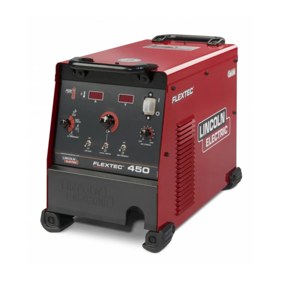
Lincoln Electric FLEXTEC 450 Operator's Manual
Lincoln electric welding system user manual
Hide thumbs
Also See for FLEXTEC 450:
- Service manual (144 pages) ,
- Operator's manual (42 pages) ,
- Installation instructions manual (8 pages)
Table of Contents
Advertisement
RETURN TO MAIN MENU
IM10062-A
FLEXTEC 450
September, 2010
For use with machines Code 11626, 11754
Safety Depends on You
Lincoln arc welding and cutting
equipment is designed and built
with safety in mind. However,
your overall safety can be
increased by proper installation
... and thoughtful operation on
your part. DO NOT INSTALL,
OPERATE OR REPAIR THIS
EQUIPMENT WITHOUT READ-
ING THIS MANUAL AND THE
SAFETY PRECAUTIONS CON-
TAINED THROUGHOUT. And,
most importantly, think before
you act and be careful.
OPERATOR' S M ANUAL
Copyright © Lincoln Global Inc.
• World's Leader in Welding and Cutting Products •
• Sales and Service through Subsidiaries and Distributors Worldwide •
Cleveland, Ohio 44117-1199 U.S.A. TEL: 216.481.8100 FAX: 216.486.1751 WEB SITE: www.lincolnelectric.com
Advertisement
Table of Contents
Troubleshooting

Related Manuals for Lincoln Electric FLEXTEC 450


Summary of Contents for Lincoln Electric FLEXTEC 450
- Page 1 RETURN TO MAIN MENU IM10062-A FLEXTEC 450 September, 2010 For use with machines Code 11626, 11754 Safety Depends on You Lincoln arc welding and cutting equipment is designed and built with safety in mind. However, your overall safety can be increased by proper installation ...
-
Page 2: California Proposition 65 Warnings
351040, Miami, Florida 33135 or CSA Standard W117.2-1974. A Free copy of “Arc Welding Safety” booklet E205 is available from the Lincoln Electric Company, 22801 St. Clair Avenue, Cleveland, Ohio 44117-1199. bE SURE THAT ALL INSTALLATION, OPERATION, MAINTENANCE AND REPAIR PROCEDURES ARE PERFORMED ONLY bY QUALIFIED INDIVIDUALS. - Page 3 SAFETY...
- Page 4 SAFETY...
- Page 5 PRÉCAUTIONS DE SÛRETÉ Pour votre propre protection lire et observer toutes les instructions et les précautions de sûreté specifiques qui parraissent dans ce manuel aussi bien que les précautions de sûreté générales suiv- antes: Sûreté Pour Soudage A L’Arc 1. Protegez-vous contre la secousse électrique: a.
- Page 6 Electric for advice or information about their use of our products. We respond to our customers based on the best information in our posses- sion at that time. Lincoln Electric is not in a position to warrant or guarantee such advice, and assumes no liability, with respect to such infor- mation or advice.
-
Page 7: Table Of Contents
TAbLE OF CONTENTS Installation ...Section A Technical Specifications ...A-1 Welding Process, Physical Dimensions ...A-2 Safety Precautions ...A-3 Select Suitable Location...A-3 Lifting...A-3 Stacking ...A-3 Environmental Limitations ...A-3 Input and Grounding Connections ...A-3 High Frequency Protection ...A-3 Input Connection ...A-4 Input Fuse and Supply Wire Considerations...A-4 Input Voltage Selection ...A-4 Cable Connections...A-5 Recommended Electrode and Work Cable for arc Welding ...A-6... -
Page 8: Installation
TECHNICAL SPECIFICATIONS - POWER SOURCE-INPUT VOLTAGE AND CURRENT Input Voltage ± 10% Model Duty Cycle 60% rating K2882-1 380 / 460 / 575 / 3 / 50 / 60 100% rating Process Duty Cycle GMAW (CV) 100% GTAW (CC) 100% SMAW (CC) 100% FCAW-GS (CV) - Page 9 PROCESS GMAW (CV) GTAW (CC) SMAW (CC) FCAW-GS (CV) FCAW-SS (CV) MODEL HEIGHT K2882-1 18.80in (478mm) OPERATING TEMPERATURE RANGE Environmentally Hardened: 14°F to 131°F (-10°C to 55°C IP23 155º(F) Insulation Class Weight does not include input cord. Output De-rated at Temperatures above 40°C. INSTALLATION WELDING PROCESS OUTPUT RANGE (AMPERES)
-
Page 10: Safety Precautions
FUSE bOX bEFORE WORKING ON THIS EQUIPMENT. TURN OFF THE INPUT POWER TO ANY OTHER EQUIPMENT CONNECTED TO THE WELDING SYSTEM AT THE DISCONNECT SWITCH OR FUSE bOX bEFORE WORKING ON THE EQUIPMENT. • DO NOT TOUCH ELECTRICALLY HOT PARTS. -
Page 11: Input Connection
WARNING ELECTRIC SHOCK can kill. ONLY A QUALIFIED ELECTRICIAN SHOULD CONNECT THE INPUT LEADS TO THE FLEXTEC™ 450. CONNECTIONS SHOULD bE MADE IN ACCOR- DANCE WITH ALL LOCAL AND NATIONAL ELECTRICAL CODES AND THE CONNECTION DIAGRAM LOCATED ON THE INSIDE OF THE RECONNECT/INPUT ACCESS DOOR OF THE MACHINE. -
Page 12: Cable Connections
See FIGURE A.2 for locating 6-pin and 14-pin con- nectors on the front of the FLEXTEC™ 450. 6 - P I N R E M O T E C O N T R O L C O N N E C T O R F O R W I R E F E E D E R 1 4 - P I N C O N N E C T O R 6-PIN REMOTE... -
Page 13: Recommended Electrode And Work Cable For Arc Welding
RECOMMENDED ELECTRODE AND WORK CAbLE SIzES FOR ARC WELDING General Guidelines Connect the electrode and work cables between the appropriate output studs of the Flextec™ 450 per the following guidelines: • Most welding applications run with the electrode being positive (+). For those applications, connect the electrode cable between the wire drive feed plate and the positive (+) output stud on the power source. -
Page 14: Safety Precautions
SAFETY PRECAUTIONS Read this entire section of operating instructions before operating the machine. WARNING ELECTRIC SHOCK can kill. • Unless using cold feed feature, when feeding with gun trigger, the electrode and drive mechanism are always electrically energized and could remain energized several seconds after the welding ceases. -
Page 15: Graphic Symbols That Appear On This Machine Or In This Manual
GRAPHIC SYMbOLS THAT APPEAR ON THIS MACHINE OR IN THIS MANUAL OPEN CIRCUIT VOLTAGE INPUT VOLTAGE OUTPUT VOLTAGE INPUT CURRENT OUTPUT CURRENT PROTECTIVE GROUND WARNING or Explosion Dangerous Voltage Shock Hazard OPERATION PRODUCT DESCRIPTION The Flextec™ 450 is a multi-process CC/CV DC inverter and is rated for 450 amps, 38 volts at a 60% duty cycle. -
Page 16: Recommended Processes And Equipment
RECOMMENDED PROCESSES AND EQUIPMENT RECOMMENDED PROCESSES The Flextec™ 450 is designed for CC-SMAW, CC-GTAW (lift tig), CV-GMAW, CV-FCAW-SS and CV-FCAW-GS welding processes. CAG (arc gouging) is also supported. PROCESS LIMITATIONS The Flextec™ 450 is suitable only for the processes listed. EQUIPMENT LIMITATIONS Operating Temperature Range is -10°... -
Page 17: Case Front Controls
CASE FRONT CONTROL DESCRIPTIONS (See Figure B.1) 1. Power Switch 2. Voltage Display Meter 3. Amperage Display Meter 4. Thermal LED 5. Output Control Dial 6. Weld Process Selector Switch 7. Hot Start Toggle Switch 8. Output Control Local/Remote Toggle Switch 9. -
Page 18: Case Back Controls
The serviceability of a product or structure utiliz- ing the welding programs is and must be the sole responsibility of the builder/user. Many variables beyond the control of The Lincoln Electric Company affect the results obtained in applying these programs. These variables include, but are... -
Page 19: Basic Modes Of Operation
Amperage Display Meter • Prior to STICK or TIG operation (current flow), the meter displays preset current value. • Prior to CV operation, the meter displays four dash- es indicating non-presettable AMPS. • During welding, this meter displays actual average amps. - Page 20 GTAW This weld mode is a constant current (CC) mode featuring con- tinuous control from 10 – 500 amps. It is intended for the GTAW TIG welding processes. Hot Start - The Hot Start control regulates the starting current at arc initiation. Hot Start can be set to “Off” and no additional current is added at arc start.
- Page 21 CV-INNERSHIELD This weld mode is a constant voltage (CV) mode fea- turing continuous control from 10 to 45 volts. It is intended for the FCAW-SS welding process and arc gouging. Hot Start – Toggle to “ON” position to provide more energy during the start of a weld.
-
Page 22: Options / Accessories
OPTIONS / ACCESSORIES General Options K2149-1 Work Lead Package. K1842-10 10ft. Weld Power Cable (Lug to Lug). Inverter and Wire Feeder Cart Rear-wheeled cart includes front casters and no-lift gas bottle platform. Convenient handles allow for easy cable storage while full length side trays store parts and tools. -
Page 23: Maintenance
SAFETY PRECAUTIONS WARNING ELECTRIC SHOCK can kill. • Only Qualified personnel should perform this maintenance. • Turn the input power OFF at the disconnect switch or fuse box before working on this equipment. • Do not touch electrically hot parts. ------------------------------------------------------------------------ See additional warning information throughout this Operator’s Manual... -
Page 24: How To Use Troubleshooting Guide
HOW TO USE TROUbLESHOOTING GUIDE Service and Repair should only be performed by Lincoln Electric Factory Trained Personnel. Unauthorized repairs performed on this equipment may result in danger to the technician and machine operator and will invalidate your factory warranty. For your safety and to avoid Electrical Shock, please observe all safety notes and precautions detailed throughout this manual. -
Page 25: Troubleshooting
Local Lincoln Authorized Field Service Facility for technical troubleshooting assistance before you proceed. TROUbLESHOOTING POSSIbLE CAUSE 1. Contact your local authorized Lincoln Electric Field Service facil- ity for technical assistance. 1. If the displays show an Err ### see the fault section for corrective action. -
Page 26: Error Codes
Observe all Safety Guidelines detailed throughout this manual USING THE STATUS LED TO TROUbLESHOOT SYSTEM PRObLEMS Errors are displayed on the user interface. In addition, there are status lights on the control pc board and the switch pc board that contain error sequences. Included in this section is information about the Status Lights and some basic troubleshooting charts for both machine and weld performance. - Page 27 DIAGRAMS FLEXTEC™ 450...
- Page 28 DIAGRAMS Enhanced Diagram FLEXTEC™ 450...
-
Page 29: Dimension Print
DIMENSION PRINT FLEXTEC™ 450... - Page 30 NOTES FLEXTEC™ 450...
- Page 31 NOTES FLEXTEC™ 450...
- Page 34 • World's Leader in Welding and Cutting Products • • Sales and Service through Subsidiaries and Distributors Worldwide • Cleveland, Ohio 44117-1199 U.S.A. TEL: 216.481.8100 FAX: 216.486.1751 WEB SITE: www.lincolnelectric.com...
Need help?
Do you have a question about the FLEXTEC 450 and is the answer not in the manual?
Questions and answers