
Subscribe to Our Youtube Channel
Related Manuals for Lincoln Electric TOMAHAWK 30K


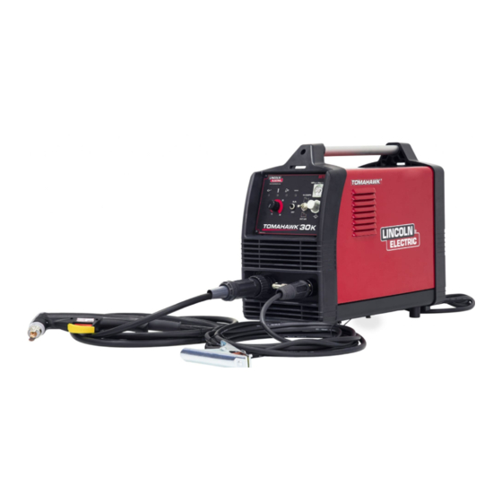
Summary of Contents for Lincoln Electric TOMAHAWK 30K
- Page 1 SVM 3184 Rev.00 02-2023 ® TOMAHAWK 30K & 45 For use with machines having code numbers: 50627 - 50628 LINCOLN ELECTRIC EUROPE www.lincolnelectric.eu...
-
Page 2: Table Of Contents
INDEX OF CONTENTS TECHNICAL SPECIFICATIONS ............................3 THERMAL PROTECTION ............................. 16 MAJOR COMPONENTS LOCATION ..........................16 OVERLOAD PROTECTION ............................19 THERMAL PROTECTION ............................. 19 INSULATED GATE BIPOLAR ............................19 TROUBLESHOOTING AND REPAIR SECTION ......................20 COVER CASE REMOVAL AND DC BUS CAPACITORS DISCHARGE PROCEDURE..........24 DISCHARGE PROCEDURE ............................ - Page 3 TECHNICAL SPECIFICATIONS NAME INDEX TOMAHAWK ® K12038-3 ® TOMAHAWK K14391-1 INPUT Input Voltage U Input Power at Rated Output EMC Class Frequency 2,2 kW @ 100% Duty Cycle TOMAHAWK ® 230V±15% 50Hz 3,3 kW @ 60% Duty Cycle 2,2 kW @ 100% Duty Cycle 120V±15% 3,3 kW @ 60% Duty Cycle ®...
- Page 4 If any electromagnetic disturbances are detected the operator must put in place corrective actions to eliminate these disturbances with, if necessary, assistance from Lincoln Electric. Before installing the machine, the operator must check the work area for any devices that may malfunction because of electromagnetic disturbances.
- Page 5 Failure to follow the instructions in this manual could cause serious personal injury, loss of life, or equipment damage. Read and understand the following explanations of the warning symbols. Lincoln Electric is not responsible for damages caused by improper installation, improper care or abnormal operation.
- Page 6 Cutting sparks can cause explosion or fire. Keep flammables away from cutting. Do not cut or gouge near flammables. Have a fire extinguisher nearby, and have a watch person ready to use it. Do not cut on drums or any closed container. The plasma arc can cause injury and burns.
- Page 7 Introduction ® ® TOMAHAWK 30K allows for cutting and grid. TOMAHAWK 45 allows for cutting, grid and gouging. ® ® The complete package TOMAHAWK 30K contains: The complete package TOMAHAWK 45 contains: Work lead – 6m, Work lead – 6m, ...
- Page 8 Controls and Operational Features 1. User Interface TOMAHAWK ® 30K: User Interface TOMAHAWK ® 30K chapter. Front panel TOMAHAWK ® 2. User Interface TOMAHAWK ® 45: See User Interface ® TOMAHAWK 45 chapter. 3. Work Lead Connector. 4. Compressor Internal Air Filter: (TOMAHAWK ®...
- Page 9 User Interface TOMAHAWK ® User Interface TOMAHAWK ® Figure 5 Figure 4 18. Home Button: Allows the user to return to 9. LED Indicator Power Switch: Lights up when the main view. the equipment is ON and connect to the power supply.
- Page 10 26. User Setup Menu: Displays the available processes Select Program and parameters. Press the control [19], to get access of user setup menu. Press [19] again to display the available process. Select a process by turning the control and confirm the selection [19].
- Page 11 TOMAHAWK ® 45 – cut TOMAHAWK ® 45 – gouging After pressing the button in the torch: After pressing the button in the torch: Preflow – purge flow before ignition of the pilot Preflow – purge flow before ignition of the pilot current –...
- Page 12 Preparing the equipment TOMAHAWK ® 45 enables be cut, grid and gouging. TOMAHAWK ® 45 does not include the accessories for gauging, but the one can be purchased separately (see TOMAHAWK ® 30K enables the cutting and grid "Accessories" chapter). process.
- Page 13 Cutting Speed The cutting speed is a function of: In order to provide indications on the most suitable setting, the following table was established, based on tests Thickness and type of material to be cut. performed on an automatic test-bench: the best results ...
- Page 14 Shield cup body is damaged or the socket [5]. incorrectly installed. Tighten the shield cup body. WARNING If for any reason you are unable to perform the recommended actions in the event of a fault, contact the nearest authorized Lincoln Electric service facility.
- Page 15 Lincoln Electric is not in a position to warrant or The frequency of the maintenance operations may vary guarantee such advice, and assumes no liability, with in accordance with the working environment where the respect to such information or advice.
-
Page 16: Thermal Protection
THERMAL PROTECTION Thermal detection devices protect the machine from excessive operating temperatures. Excessive temperatures may be caused by a lack of cooling air or operating the machine beyond the duty cycle and output rating. If excessive operating temperatures should occur, the yellow LED will light and the detection device will prevent output voltage or current. These detection devices are self-resetting once the machine cools sufficiently. - Page 17 MAJOR COMPONENTS LOCATION ® TOMAHAWK Air Filter Front UI Board Torch Connector Power Board Pressure Gauge Gas solenoid...
-
Page 18: Overload Protection
the duty cycle and output rating. If excessive OVERLOAD PROTECTION operating temperature should occur, the Thermal Overload indicator on the front panel, will turn ON TOMAHAWK 30K & 45 are electrically protected ® and the thermostat will prevent output current. from producing higher than normal output current. -
Page 19: Troubleshooting And Repair Section
TROUBLESHOOTING AND REPAIR SECTION How to use troubleshooting Guide Troubleshooting Guide Side panels removal and capacitor discharge procedure... - Page 20 HOW TO USE TROUBLESHOOTING GUIDE Service and repair should be performed by only Lincoln Electric Factory Trained Personnel. Unauthorized repairs performed on this equipment may result in danger to the technician and machine operator and will invalidate your factory warranty. For your safety and to avoid Electrical Shock, please observe all safety notes and precautions detailed throughout this manual.
- Page 21 WARNING 4. Test the machine to determine if the failure symptom has been corrected by the replacement PC board. NOTE: Allow the machine to heat up so that all ELECTRIC SHOCK can kill electrical components can reach their operating temperature. ...
- Page 22 TROUBLESHOOTING !! WARNING !! BEFORE CONNECT POWER SUPPLY, MAKE A CAREFUL VISUAL INSPECTION INSIDE THE MACHINE, CHECK ALL THE BOARDS AND HARNESSES. POSSIBLE AREAS OF CHECKS & RECOMMENDED COURSE PROBLEMS / SYMPTOMS MISADJUSTMENT(S) OF ACTION THE INPUT FUSES PERFORM THE INPUT RECTIFIER BRIDGE TEST ...
-
Page 23: Cover Case Removal And Dc Bus Capacitors Discharge Procedure
DISCHARGE PROCEDURE WARNING Service and repair should be performed only by Lincoln Electric factory trained personnel. Unauthorized repairs performed on this equipment may result in danger to the technician or machine operator and will invalidate your factory warranty. For your safety and to avoid electrical shock, please observe all safety notes and precautions detailed throughout this manual. - Page 24 ® TOMAHAWK 30K & 45 –COVER REMOVAL Necessary tool: PH02 screwdriver 7mm wrench Procedure: 1. Turn ON/OFF switch to OFF position. 2. Disconnect Input Power from the machine! 3. Remove the 7 screws (A) on the back panel. See above pictures 4.
-
Page 25: Discharge Procedure
DISCHARGE PROCEDURE WARNING as there are no accessible points where to connect ELECTRIC SHOCK can kill wait 5 the resistor to discharge the capacitors, minutes, after having switched off and Have an electrician install and service this equipment disconnected the machine from the Turn the input power off at the fuse box before working mains, before carrying out any kind of on equipment... -
Page 26: Input Rectifier Bridge Resistance Test
If for any reason you do not understand the test procedures or are unable to perform the test/repairs safely, contact your Local Lincoln Electric Service Department for electrical troubleshooting assistance before you proceed. - Page 27 INPUT RECTIFIER BRIDGE RESISTANCE TEST (continued) Image is from TH 30K Image is from TH 45 TEST PROCEDURE 1. Remove main input power to the Tomahawk® 30K or 45 2. Follow the instruction available at the Discharge procedure page. 3. Disconnect the cables from rectifier bridge terminals 4.
-
Page 28: Main Board Thermal Sensors Test
MAIN BOARD THERMAL SENSORS TEST WARNING Service and repair should be performed by only Lincoln Electric factory trained personnel. Unauthorized repairs performed on this equipment may result in danger to the technician or machine operator and will invalidate your factory warranty. For your safety and to avoid electrical shock, please observe all safety notes and precautions detailed throughout this manual. - Page 29 MAIN BOARD THERMAL SENSORS TEST PTC on IGBTs PTC on Output Diodes IGBT and Output diode heatsink TH 30K Figure 1 TEST PROCEDURE TH 45 Figure 2 Remove main input power to the Tomahawk® 30K or 45 Follow the instruction available at the Discharge procedure page. Disconnect the connectors “OT1”...
-
Page 30: Power Board Voltage Test
POWER BOARD VOLTAGE TEST WARNING Service and repair should be performed by only Lincoln Electric factory trained personnel. Unauthorized repairs performed on this equipment may result in danger to the technician or machine operator and will invalidate your factory warranty. For your safety and to avoid electrical shock, please observe all safety notes and precautions detailed throughout this manual. - Page 31 POWER BOARD VOLTAGE TEST (continued) INPUT VOLTAGE Figure 1 Image from TH 30K Figure 2 Image from TH 45 TEST PROCEDURE Use always electrically insulate gloves during this test procedure 1. Carefully apply 230Vac +/- 15% input voltage via the input cable to the Tomahawk® 30K or 45 2.
- Page 32 POWER BOARD VOLTAGE TEST (continued) FANS SUPPLY VOLTAGE J7 & J8 TH 30K TH 45 TEST PROCEDURE Use always electrically insulate gloves during this test procedure 1. Carefully apply 230Vac +/- 15% input voltage via the input cable to the Tomahawk® 30K or 45 Switch to ON position the mains switch located on the back of the machine Follow the below tables tests: FOR TH 30K : Power supply for the Compressor area and Main Board area...
- Page 33 POWER BOARD VOLTAGE TEST (continued) AUXILIARY SUPPLY VOLTAGE TH 30K TH 45 TEST PROCEDURE Use always electrically insulate gloves during this test procedure 1. Carefully apply 230Vac +/- 15% input voltage via the input cable to the Tomahawk® 30K or 45 2.
- Page 34 POWER BOARD VOLTAGE TEST (continued) AUXILIARY SUPPLY VOLTAGE to UI (User Interface) ONLY TH 45 TH 45 control board TEST PROCEDURE Use always electrically insulate gloves during this test procedure 4. Carefully apply 230Vac +/- 15% input voltage via the input cable to the Tomahawk® 30K or 45 5.
- Page 35 POWER BOARD VOLTAGE TEST (continued) GAS SOLENOID SUPPLY VOLTAGE TH 30K TH 45 TEST PROCEDURE Use always electrically insulate gloves during this test procedure 1. Carefully apply 230Vac +/- 15% input voltage via the input cable to the Tomahawk® 30K or 45 2.
-
Page 36: Disassembly Operations
DISASSEMBLY OPERATIONS MAIN PCB REMOVAL AND REPLACEMENT PROCEDURE (30K & 45) Figure 1 REMOVAL PROCEDURE Necessary tools: - Pliers - PH02 screwdriver 1. Remove main input power to the machine 2. Remove the cover of the machine following the cover removal procedure. 3. - Page 37 DISASSEMBLY OPERATIONS FAN REMOVAL AND REPLACEMENT PROCEDURE Figure 1 – TH 45 Figure 1a – TH 30K REMOVAL PROCEDURE Necessary tools: - PH02 screwdriver 1. Remove main input power to the machine 2. Remove the cover of the machine following the cover removal procedure. 3.
- Page 38 DISASSEMBLY OPERATIONS GAS SOLENOID REPLACEMENT PROCEDURE Figure 1 Figure 2 REMOVAL PROCEDURE Necessary tools: - Pliers - PH02 screwdriver 1. Remove main input power to the machine 2. Remove the cover of the machine following the cover removal procedure. 3. Follow the instruction available at the Discharge procedure page. 4.
- Page 39 DISASSEMBLY OPERATIONS FRONT PANEL BOARD REMOVAL AND REPLACEMENT PROCEDURE TH 45 Figure 2 Figure 1 REMOVAL PROCEDURE Necessary tools: Figure 3 - PH02 screwdriver - 7mm socket wrench - Pliers 1. Remove main input power to the machine 2. Remove the cover of the machine following the cover removal procedure. 3.
- Page 40 DISASSEMBLY OPERATIONS FRONT NAMEPLATE ASSEMBLY REMOVAL AND REPLACEMENT PROCEDURE TH30K Figure 1 REMOVAL PROCEDURE Necessary tools: - PH02 screwdriver 1. Remove main input power to the machine 2. Remove the cover of the machine following the cover removal procedure. 3. Follow the instruction available at the Discharge procedure page. 4.
- Page 41 DISASSEMBLY OPERATIONS FRONT PANEL BOARD REMOVAL AND REPLACEMENT PROCEDURE TH 30K Figure 1 Figure 2 REMOVAL PROCEDURE Necessary tools: - PH02 screwdriver 1. Remove main input power to the machine 2. Remove the cover of the machine following the cover removal procedure. 3.
- Page 42 DISASSEMBLY OPERATIONS FRONT PANEL REMOVAL AND REPLACEMENT PROCEDURE TH 30K REMOVAL PROCEDURE Necessary tools: - PH02 screwdriver 1. Remove main input power to the machine 2. Remove the cover of the machine following the cover removal procedure. 3. Follow the instruction available at the Discharge procedure page. 4.
- Page 43 DISASSEMBLY OPERATIONS COMPRESSOR REMOVAL AND REPLACEMENT PROCEDURE TH 30K Figure 1 REMOVAL PROCEDURE Necessary tools: - PH02 screwdriver - 12mm wrench 1. Remove main input power to the machine 2. Remove the cover of the machine following the cover removal procedure. 3.
-
Page 44: Retest After Repair
RETEST AFTER REPAIR Should a machine under test be rejected for any reason requiring the removal of any mechanical part that could affect the machine’s electrical characteristics, or if any electrical components are repaired or replaced, the machine must be retested. Machine input and output TOMAHAWK ®... -
Page 45: Calibration Procedure For Th 30K
CALIBRATION PROCEDURE for TH 30K Calibrate the Min and Max current: 1. Add a 10K resistor between PIN3 and PIN9 of torch connector, then turn on the machine; 2. Machine switch into TEST mode; short the PIN4 and PIN7 of torch connector; 3. -
Page 46: Calibration Procedure For Th 45
CALIBRATION PROCEDURE for TH 45 Calibrate the Min and Max current: 1. Keep Push both two buttons on front panel and turn on the machine; 2. Machine switch into TEST mode; short the PIN4 and PIN7 of torch connector; 3. Connect proper pressure air into machine; 4. -
Page 47: Electrical Schematics
ELECTRICAL SCHEMATICS ® Block Diagram TOMAHAWK... - Page 48 ELECTRICAL SCHEMATICS ® Block Diagram TOMAHAWK...
-
Page 49: Note
NOTE...
Need help?
Do you have a question about the TOMAHAWK 30K and is the answer not in the manual?
Questions and answers