Table of Contents
Advertisement
Quick Links
See also:
User Manual
Advertisement
Table of Contents

Related Manuals for BK Precision 8510


Summary of Contents for BK Precision 8510
- Page 1 INSTRUCTION MANUAL MODEL 8510 Model 85 Model 851 1 1 1 0 600W 0 600W Programmable Programmable DC Model Model 0 600W 0 600W Programmable Programmable E E E E lectronic Load lectronic Load lectronic Load lectronic Load...
- Page 2 Instruction Manual Model 8510 PROGRAMMABLE DC ELECTRONIC LOAD...
-
Page 3: Table Of Contents
TABLE OF CONTENTS QUICK REFERENCE ..........6 Location................22 The Front Panel ..........6 Installation ............... 23 The Rear Panel ..........7 Bench Operation..............23 Front Panel Display......... 7 Input Connections..............23 Immediate Action Keys ........8 Power Cord..............23 Front Panel Menus.......... -
Page 4: Warranty Information
Warranty Information Certification We certify that this product met its published specifications at time of shipment from the factory. Assistance The above statements apply only to the standard product warranty. Warranty options product maintenance agreements and customer assistance agreements are also available. Safety Summary The following general safety precautions must be observed during all phases of operation of this instrument. -
Page 5: Safety Symbols
Safety Symbols Direct current Alternating current Both direct and alternating current Protective earth (ground) terminal Caution (refer to accompanying documents) WARNING The WARNING sign denotes a hazard. It calls attention to a procedure, practice, or the like, which, if not correctly performed or adhered to, could result in personal injury. -
Page 6: Quick Reference
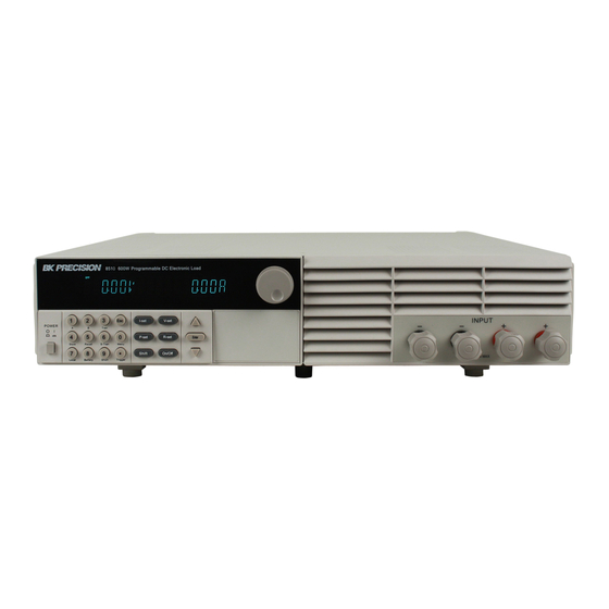
Quick Reference The Front Panel 16-character display shows voltage and current measurements. Rotary knob Power switch ON/OFF Entry keys:( ( ( ( numeric keys) ) ) ) Enter values. Increasing or decreasing the setup values. Menu commands. Keypad: Enable/disable input. Setup the current, resistance and voltage modes. -
Page 7: The Rear Panel
The Rear Panel 3 Pin IEC320 ac input connector. (Power code requires ground conductor). 4 Pin Trigger and Remote sensing connectors. 9-Pin COM port interface connector. Power switch (110V / 220V) Front Panel Display power off Trigger Indicates that the electronic load is waiting an initiate and trigger to occur. -
Page 8: Immediate Action Keys
Immediate Action Keys V-set V-set Choosing CV mode and setting the input of regulation voltage mode I-set I-set Choosing CI mode and setting the input of regulation current mode P-set Choosing CP mode and setting the input of regulation power mode R-set Choosing CR mode and setting the input of regulation resistor mode Shift... -
Page 9: Menu Operation
△ △ △ △ Scrolling keys let you move through the commands in the presently selected function men up the next command in the list. Function menus are circular; you can return to the startin position by continuous pressing the key. ▽... - Page 10 ADC UPDATE RATE HIGH LOW<DEFAULT> TRIGGER SOURCE Choosing the trigger signals source. Shift Trigger IMMEDIATE<DEF> Trigger signals from EXTERNAL Trigger signals from the TRIG connector in the rear panel. Communication command trigger mode. CONNECT MODE MAXTIDLEXING SEPARATE<DEF> BAUDRATE SET Setting baud rate. 4800<DEFAULT>...
-
Page 11: General Information
General Information Document Orientation This manual describes the operation of the model 8510 DC Electronic Load. Unless otherwise noted, all units will be referred to by the description "electronic load" throughout this instruction manual. The following documents and software are shipped with your electronic load. This User's Guide (this document), contains installation, checkout, front panel information and detailed programming information. -
Page 12: Accessories
The electronic load contains a processor, serial port connector, front-panel keypad and VFD, and other circuits common to the other entire load module. The model 8510 serial electronic load operates in constant current (CC) mode, constant voltage (CV) mode, or constant resistance (CR) mode and constant power (CW) Mode. -
Page 13: Remote Programming
Remote Programming The electronic load may be remotely programmed from the computer via the IT-E131 isolated communication cable Operating Modes The four modes of operation are: 1: Constant current (CC). 2: Constant voltage (CV). 3: Constant resistance (CR). 4: Constant power (CW) Constant Current(... -
Page 14: Constant Voltage Mode
VOLT SETTING LOAD INPUT VOLTAGE LOAD CURRENT CONSTANT VOLTAGE MODE Constant Power (CW) Mode In this mode, the electronic load’s power consumption will be in accordance with the programmed value, regardless of the input voltage. The CW mode can be set with front panel keys. The CW mode parameters are discussed in the following paragraphs. -
Page 15: Pulse
2.0ms 3.0ms Continuous Transient Operation Pulse Switch to value B upon receiving one trigger signal , after taking the pulse time(TWD) of value B, the load will return to Value A . 10ms 10ms TRIG TRIG Pulsed Transient Operation Trigger Mode Switches the state between value A and value B once trigger signal is received. -
Page 16: Triggered Operation
GROUP Total = 1000 steps 1000 steps 500 00 00 00 steps 500 steps 250 steps 250 steps 250 steps 250 steps 120 steps 120 steps 120 steps 120 steps 120 steps 120steps 120 steps 120 steps When receiving one trigger signal, it will start the list operation until receiving another trigger signal or finish the List operation. -
Page 17: Input On/Off
Input On/Off Electronic load's input can be toggled on/off at the front panel. Turning the input off (zero current) does not affect the programmed settings. The input will return to the previously programmed values when the input is turned on again. NOTE The Input On/Off command supersedes the mode commands and Short Test On/Off command. -
Page 18: Remote Sense Function
When working in CR, CC and CP mode, input current is ascending continuously, the load current will be limited by a current limit circuit, Load will work in the over current protection state , VFD display the information as CC. When work in CV mode, transition mode and List mode, Input current exceeds the current limit, Buzzer is mooing, VFD display the flashing current value. -
Page 19: Saving And Recalling Settings
TRIG: A TTL-compatible input that responds to external edge trigger signal. A trigger applied to this input can be used to change settings (voltage, current, resistance, etc.), toggle between settings in transient-toggle mode, or generate a pulse in transient-pulse mode. You must set the remote sense mode in the menu before using the remote sense function. -
Page 20: Battery Testing
Battery Testing A DC load is well suited to verify that a battery is working properly. Only with the correct load testing, the battery can be confirmed if it was being the expectant life curve location. The electronic loads can be used to test any type of battery. -
Page 21: Von/Voff Operation
Battery Voltage Min voltage Load Sink Current Von/Voff Operation You can set voltage value Von/Voff to control the input state on/off for electronic load. When the input voltage reaches the Von value, the load’s input state is on. When the input voltage reaches the Voff value, the load’s input state is off. Action for set Von/Voff value: Shift Menu... -
Page 22: Installation
Installation Inspection Damage When you receive your electronic load, inspect it for any obvious damage that may have occurred during shipment. If there is damage, notify the shipping carrier and nearest Agent office and Support Office immediately. Items Supplied The following user replaceable items are included with your electronic load. Item Description Power Cord... -
Page 23: Installation
Outline Diagram Unit (mm) Bench Operation A fan cools the electronic load by drawing air through the button and sides and exhausting it out the back. Minimum clearances for bench operation are 25 mm along the sides. CAUTION Do not block the fan exhaust at the rear of the Load. Input Connections Power Cord Connect the power cord to the IEC 320 connector on the rear of the unit. -
Page 24: Trigger And Remote Sensing Connections
Trigger and Remote Sensing Connections A 4-pin connector and a quick-disconnect mating plug are provided on rear panel for accessing input signals and remote sensing, all leads connected to the connector should be twisted and shielded to maintain the instrument's specified performance. -
Page 25: In Case Of Trouble
Check the fuse. If fuse is blown, please replace it according to the following specification. Model Fuse specification Fuse specification (110VAC) (220VAC) 8510 T0.5A 250V T0.3A 250V Location of Fuse Fuse Front Panel Operation Display 16-character fluorescent display for showing measurements and programmed values. -
Page 26: Example
The selected input channel is in the Indicates that the electronic load is in remote resistance (CR) mode. state (RS-232). In the remote state, only the active key is the Local key. Tran Shift The selected input channel is enabled Indicates that the shift key has been pressed. -
Page 27: P-Set
STEP 3 CURRENT=*.***A Enter the original value which displayed in the VFD or enter a new value by using number keys or Rotary knob to adjust the voltage value Enter STEP 4 0.000V *.***A Press to confirm Setup the input current at 4.33A. Method 1: To set up by using number keyboard I-set I-set... -
Page 28: V-Set
R-set Step 1 RESISTANCE =0000R Press Step 2 RESISTANCE=*****R enter a new value by using numeric keys or Rotary knob to adjust the resistance value Enter 0.000W R:0000R Step 3 Press to confirm. V-set (set up a constant voltage from 1.5V to Max voltage) 8500A electronic load can be setup for a constant voltage. -
Page 29: Transition Parameter Setting
Transition Parameter Setting Shift S-Tran Users could press to set the transition parameter. Shift S-Tran LEVEL A = ***** Setup value A Enter WIDTH A = ****** Setup time width of value A Enter LEVEL B=***** Setup value B Enter WIDTH B= ***** Setup time width of value B Enter... -
Page 30: Toggled Transient Operation
For example: When load receiving one trigger signal, it will switch to 10A current value, and taking 10mS to return the current value of 5A. 10ms 10ms TRIG TRIG Pulsed Transient Operation Action On/Off 1. Select the operation mode ( CC,CV,CR or CP ), and set a proper value, press to turn off the load input. -
Page 31: List Operation
Trigger Shift 3. Press switch to the current value of 10A. Shift Trigger 4. Press , switch between 5A and 10A. Shift Tran 5. Press again to stop the transient operation. List Operation Users can use the front panel keypad or the included software (PV 8500) to program the list sequence. Please refer to the software user’s guide. -
Page 32: Quick Recall Function
Enter 18) Press to confirm. Quick Recall Function This function allows you to recall 10 groups numbers which were stored previously. Steps: Shift Menu Press Enter Press ▼ to CONFIG , press into submenu, press ▼ to SHORTCURT RECALL Enter Enter , select >... - Page 33 Enter and begin to edit the automatic testing file, , VFD shows MAX CURR= * * * * ..** ** ** **A , which means Press setting the maximum of voltage. The maximum is bigger than 3A , which means CC mode is in high value, here, Enter the maximum is 3A .
-
Page 34: Automatic Testing
15) Repeat 9 )~14), and set the other process step by step as follows: CONST CURRENT,0A,SHORT OFF, READ BACK V, 5.9V, 6.4V,1S CONST VOLTAGE, 5V, SHORT OFF,READ BACK A, 0.205A, 0.245A,1S CONST VOLTAGE, 3V, SHORT OFF, READ BACK A, 0.205A,0.245A,1S CONST VOLTAGE, 2V,SHORT OFF, READ BACK A, 0.205A,0.245A, 1S CONST CURRENT, 0A, SHORT ON, READ BACK A,0A,0.245A, 1S 16) VFD displays SHORT TEST FILE*, which requests saving the files edited to EEPROM, automatically testing... -
Page 35: Select The Precision Between Low Range & High Range
2 decimal points (xx.xx) compared to 3 decimal points. To toggle from the 120A to the 12A range, press +▲, now the resolution will be set to 1mA. Specifications Parameter 8510 Voltage 0 to 120V Input rating Current... -
Page 36: Remote Operation Mode
CW Mode Regulation 0-100W ±(1%+0.1%FS) Input current ≥FS 10% 100-600W ±(1%+0.1%FS) 100mW Input Voltage≥FS 10% ) 0-12A ±(0.1% + 0.1%FS) Current Measurement 0-120A ±(0.2%+0.15%FS) 10mA 0-18V ±(0.02% + 0.02%FS) Voltage Measurement 0-120V ±(0.02% + 0.025%FS) 10mV Power Measurement 0-100W ±(1%+0.1%FS) Input current≥FS 10% 100-600W ±(1%+0.1%FS) -
Page 37: Communication Between Electronic Load And Pc
The DB9 interface connector on the rear panel of electronic load is TTL voltage level; you can use the communication cable (IT-E132) to connect the DB9 interface connector of the electronic load and the USB interface connector of computer for the communication. IT-E131 communication IT-E132 communication cable... - Page 38 Reading the max setup input current. Setting max input power. Reading the max setup input power. Selecting CC/CV/CW/CR operation mode of Electronic load. Reading the operation mode. Setting CC mode current value Reading CC mode current value Setting CV mode voltage value Reading CV mode voltage value Setting CW mode watt value Reading CW mode watt value...
-
Page 39: Communication Protocol
Reading timer value of FOR LOAD ON Disable/Enable timer of FOR LOAD ON Reading timer state of FOR LOAD ON Setting communication address Enable/Disable LOCAL control mode. Enable/Disable remote sense mode. Reading the state of remote sense mode. Selecting trigger source. Reading trigger source. - Page 40 byte Address (0—0XFE) byte Command ( 20H ) .byte Operation mode ( 0 is front panel operation mode , 1 is remote operation mode ) From 5 to 25 byte System reserve byte Sum code NOTE Front panel operation state is not in effect if electronic load is in calibration mode. 2.
- Page 41 byte Command ( 24H/25H ) byte The Lowest byte of max current value byte The Lowest byte of max current value byte The higher byte of max current value byte The highest byte of max current value From 8 to 25 byte System reserve Sum code...
- Page 42 7. Setting / Reading CC mode current value ( ( ( ( 2AH/2BH ) ) ) ) byte Start bit ( AAH ) byte Address (0—0XFE) byte Command ( 2AH/2BH ) byte The lowest byte of current value byte The lower byte of current value. byte The higher byte of current value.
- Page 43 byte The highest byte of max power value to 25 byte System reserve byte Sum code NOTE Represent power by 4 bytes of Hex. Lower bytes are in the front location, higher bytes are in the later location. For example :power is 200.000W, Hex is 0X00030d40, 4th byte is 0X40, 5th byte is 0X0d, 6th byte is 0X03 , 7th byte is 0X00。...
- Page 44 byte Sum code 12. Setting /Reading CV mode transient voltage and timer parameter. ( ( ( ( 34H/35H ) ) ) ) byte Start bit ( AAH ) byte Address (0—0XFE) byte Command ( 34H/35H ) From 4 to 7 byte.
- Page 45 From 10 byte to 13 byte Setting value of resistance B (Lower bytes are in the front location, higher bytes are in the later location) From 14 byte to 15 byte Time value of timer B (Lower bytes are in the front location, higher bytes are in the later location) (1 represent 0.1mS) byte Transition operation mode (0 is CONTINUES,1 is PULSE,2 is TOGGLED)
- Page 46 From 10 to 11 byte Time value of current step (Lower bytes are in the front location, higher bytes are in the later location) (1 represent 0.1mS) From 12 to 25 byte System reserve byte Sum code 19. Setting / Reading one of the step’s voltage and time values. (42H/43H) byte Start bit ( AAH ) byte...
- Page 47 byte Start bit ( AAH ) byte Address (0—0XFE) byte Command ( 48H/49H ) From 4 to 13 byte LIST file name (ASSIC code ) From 14 to 25 byte System reserve byte Sum code 23. Selection / Reading the memory space mode for storing list steps. (4AH/4BH) byte Start bit ( AAH ) byte...
- Page 48 byte The highest byte of time value in timer. From 8 to 25 byte System reserve byte Sum code Time unit in Timer is S, 1S is represented by 1. 27. Disable / Enable timer of FOR LOAD ON (52H); Reading timer state of FOR LOAD ON (53H) byte Start bit ( AAH )
- Page 49 byte Start bit ( AAH ) byte Address (0—0XFE) byte Command ( 58H/59H ) byte Trigger mode (0:Keypad,1 External,2.command) From 5 to 25 byte System reserve byte Sum code 32. Sending a trigger signal to trigging the electronic load. (5AH) byte Start bit ( AAH ) byte...
- Page 50 later location) From 12 to 15 byte Actual input power value (Lower bytes are in the front location, higher bytes are in the later location) byte Operation state register From 17 to 18 byte Demand state register From 19 to 25 byte System reserve byte...
- Page 51 If Load is not in protection state, users could do the calibration operation. 37. Getting the calibration mode state ( ( ( ( 61H ) ) ) ) byte Start bit ( AAH ) byte Address (0—0XFE) byte Command ( 61H ) byte Calibration protection state From 5...
- Page 52 40. Calibrate current value ( ( ( ( 64H ) ) ) ) byte Start bit ( AAH ) byte Address (0—0XFE) byte Command ( 64H ) byte Current calibration point ( 1~4 ) From 5 to 25 byte System reserve byte Sum code NOTE...
- Page 53 byte Command ( 67H/68H ) From 4 to 23 byte Demarcate information ( ASIC code ) byte System reserve byte System reserve byte Sum code 44. Restore the factory default calibration data ( ( ( ( 69H ) ) ) ) byte Start bit ( AAH ) byte...
- Page 54 From 4 to 22 byte Information in bar code ( ASICmode ) From 23 to 25 byte System reserve byte Sum code Bar code rule : : : : All of bar cod of our products is distinguished by the former three characters. batch Identity Year...
-
Page 55: Service / Warranty Information
Service Information Warranty Service: Please return the product in the original packaging with proof of purchase to the address below. Clearly state in writing the performance problem and return any leads, probes, connectors and accessories that you are using with the device. Non-Warranty Service: Return the product in the original packaging to the address below. - Page 56 Yorba Linda, CA 92887-4610 Declares that the below mentioned product Electronic Load Product Name: 8510 Part Numbers: complies with the essential requirements of the following applicable European Directives: Low Voltage Directive 73/23/EEC (19.02.73) amended by 93/68/EEC (22.07.93) Electromagnetic Compatibility (EMC) 89/336/EEC (03.05.88) amended by 92/68/EEC (22.07.93)
- Page 57 22820 Savi Ranch Parkway • Yorba Linda, CA 92887 481-554-9-001 Printed in China...
Need help?
Do you have a question about the 8510 and is the answer not in the manual?
Questions and answers