Sign In
Upload
Download
Table of Contents
Contents
Add to my manuals
Delete from my manuals
Share
URL of this page:
HTML Link:
Bookmark this page
Add
Manual will be automatically added to "My Manuals"
Print this page
×
Bookmark added
×
Added to my manuals
Manuals
Brands
BK Precision Manuals
Power Supply
9201
User manual
BK Precision 9201 User Manual
9200 series multi-range dc power supply
Hide thumbs
1
2
3
4
5
6
7
8
9
Table Of Contents
10
11
12
13
14
15
16
17
18
19
20
21
22
23
24
25
26
27
28
29
30
31
32
33
34
35
36
37
38
39
40
41
42
43
44
45
46
47
48
49
50
51
52
53
54
55
56
57
58
59
60
61
62
63
64
page
of
64
Go
/
64
Contents
Table of Contents
Troubleshooting
Bookmarks
Table of Contents
Safety Summary
Compliance Statements
Ce Declaration of Conformity
Safety Symbols
Table of Contents
1 General Information
Product Overview
Package Contents
Product Dimensions
Rackmount Installation
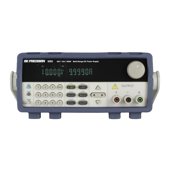
Front Panel Overview
Front Panel Description
Keypad Overview
Keypad Description
Rear Panel Overview
Rear Panel Description
Display Overview
Display Description
2 Getting Started
Input Power and Fuse Requirements
Input Power
Fuse Requirements
Line Voltage Selection
Output Connections
Preliminary Check
Self-Test Errors
Output Check
Check Model and Firmware Version
3 Front Panel Operation
Menu Options
How to Access the Menu
Configure Voltage and Current Output
Setting Voltage
Setting Current
Remote Sense
Voltage/Current Measurement
SYSTEM Menu
Voltage Limit Setting
Configure Overcurrent Protection (OCP)
Configure Power-On State
Remote Communication Configuration
Enable/Disable Key Sound
Lock/Unlock Rotary Knob
Configure Trigger Source
Save/Recall Instrument Settings
Timer Function
Restore Factory Default Settings
LIST Menu
Enable/Disable List Mode
Load List File
Edit List File
Overvoltage Protection (OVP)
Key Lock
Digital Voltmeter (DVM)
4 Remote Operation
Interface Configuration
Usb
Gpib
5 Remote Commands
Parameter Definition
SCPI Status Register
IEEE488.2 Common Commands
STATUS Subsystem
SYSTEM Subsystem
TRIGGER Subsystem
SOURCE Subsystem
MEASUREMENT Commands
LIST Commands
6 Troubleshooting Guide
General
Remote Control
7 Specifications
8 Calibration
Service Information
Limited Three-Year Warranty
Advertisement
Quick Links
1
Specifications
2
Calibration
Download this manual
9200 Series
Multi-Range DC Power Supply
Models: 9201, 9202, 9205, 9206
USER MANUAL
i
1.800.561.8187
information@itm.com
www.
.com
Table of
Contents
Previous
Page
Next
Page
1
2
3
4
5
Advertisement
Table of Contents
Need help?
Do you have a question about the 9201 and is the answer not in the manual?
Ask a question
Questions and answers
Related Manuals for BK Precision 9201
Power Supply BK Precision 9202 User Manual
9200 series multi-range dc power supply (64 pages)
Power Supply BK Precision 9205 User Manual
9200 series multi-range dc power supply (64 pages)
Power Supply BK Precision 9206 User Manual
9200 series multi-range dc power supply (64 pages)
Power Supply BK Precision 9240 Series User Manual
Multi-range dc power supplies (82 pages)
Power Supply BK Precision 9241 User Manual
Multi-range dc power supplies (82 pages)
Power Supply BK Precision 9242 User Manual
Multi-range dc power supplies (82 pages)
Power Supply BK Precision 9200B Series User Manual
Multi-range dc power supply (60 pages)
Power Supply BK Precision 9201B User Manual
Multi-range dc power supply (60 pages)
Power Supply BK Precision 9202B User Manual
Multi-range dc power supply (60 pages)
Power Supply BK Precision 9205B User Manual
Multi-range dc power supply (60 pages)
Power Supply BK Precision 9206B User Manual
Multi-range dc power supply (60 pages)
Power Supply BK Precision 9120 Instruction Manual
Single output programmable dc power supply (119 pages)
Power Supply BK Precision 9110 Instruction Manual
100w multi range 60v/5a dc power supply (13 pages)
Power Supply BK Precision 9110 User Manual
Multi range dc power supply (23 pages)
Power Supply BK Precision 9120A User Manual
Single output programmable dc power supply (50 pages)
Power Supply BK Precision 9171B User Manual
Programmable dc power supplies (190 pages)
This manual is also suitable for:
9202
9205
9206
9200 series
Table of Contents
Save PDF
Print
Rename the bookmark
Delete bookmark?
Delete from my manuals?
Login
Sign In
OR
Sign in with Facebook
Sign in with Google
Upload manual
Upload from disk
Upload from URL


Need help?
Do you have a question about the 9201 and is the answer not in the manual?
Questions and answers