Table of Contents
Advertisement
Quick Links
RETURN TO MAIN MENU
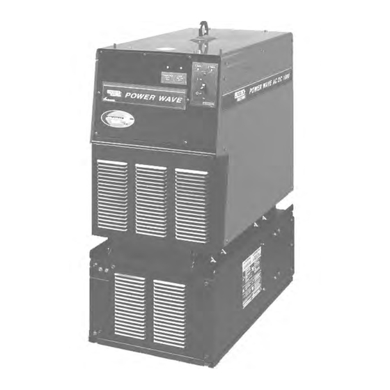
Power Wave AC/DC 1000
June, 2009
Safety Depends on You
Lincoln arc welding and cutting
equipment is designed and built
with safety in mind. However, your
overall safety can be increased by
proper installation ... and thought-
ful operation on your part.
nd, most
importantly, think before you act
and be careful.
Copyright © Lincoln Global Inc.
Advertisement
Table of Contents

Related Manuals for Lincoln Electric POWER WAVE 11124


Summary of Contents for Lincoln Electric POWER WAVE 11124
- Page 1 RETURN TO MAIN MENU POWER WAVE AC/DC 1000 June, 2009 Safety Depends on You Lincoln arc welding and cutting equipment is designed and built with safety in mind. However, your overall safety can be increased by proper installation ... and thought- ful operation on your part.
- Page 8 T T h h a a n n k k Y Y o o u u...
- Page 11 EN 60974-1...
- Page 12 -------------------------------------------------------------...
- Page 13 Do not operate with covers removed Disconnect input power before servicing Do not touch electrically live parts Only qualified persons should install, use or service this equipment INPUT SUPPLY CONNECTION DIAGRAM WARNING Do not operate with covers removed Disconnect input power before servicing Do not touch electrically live parts Only qualified persons should install, ELECTRIC...
- Page 17 Connection Diagram- Typical Single Arc System (Power Feed 10A Controller) Work Studs E lectrode Studs K1785-XX Wire Feeder Control Cable * Work Cable(s) * Electrode Cable(s) 67 Lead * Refer to "Output Cable Guidelines" for recommended cable size. Arclink (5 Pin) Wire Feeder (14 Pin) K1543-XX Arclink Control Cable...
- Page 19 Connection Diagram- Typical Tandem Arc System ( Power Feed 10A Controller) Wire Feeder (14 Pin) Arc link (5 Pin) Work Studs Electrode Studs Wir e Reel and Mountings K1785-XX Wire Feeder Control Cabl es * Work Cables K2362-1 14 Pin Connector Head K231-XXX Work Piece...
- Page 23 Connection Diagram - Parallel Machines (Example depicts a single arc grouping, and may be repeated for each arc in the system) Ethernet Work Connect to optional K2282-1 System Interface for Synchronized Multiple Arc Applications Rea r view of machines K 179 5-XX C ables S 12 (Input) Front view o f machines * Work Cables...
- Page 25 Common Connection Diagram COMMON CONNECTION (LOCAT ED CLOSE TO POWER SOURCES) WORK PIECE...
- Page 26 FIGURE A.2 POWER WAVE WORK...
- Page 27 1 2 3 4 5 6 7 8 DIRECTION OF TRAVEL CONNECT ALL SENSE LEADS AT THE END OF THE WELD. CONNECT ALL WORK LEADS AT THE BEGINNING OF THE WELD.
- Page 28 POWER SOURCE POWER SOURCE POWER SOURCE POWER SOURCE POWER SOURCE POWER SOURCE...
- Page 31 1 2 3 9 10 11 12...
- Page 33 JUMPER PIN 5 JUMPER PIN 12 EXT T E E R R N N AL I/O AL I/O C C O O N N N N E E CTOR CTOR FEE E DHE DHEA A D D P. P.C C . . BOA BOAR R D D...
- Page 34 ETHERNET P.C. BOARD CONTROL P.C. BOARD FEEDHEAD P.C. BOARD...
- Page 35 (*DEFAULT SETTINGS SHOWN) 1 2 3 4 5 6 7 8 WORK VOLTAGE SENSE ENABLE OBJECT INSTANCE AUTO MAP GROUP SELECT (*DEFAULT SETTINGS SHOWN) 1 2 3 4 5 6 7 8 SPEED RANGE OBJECT INSTANCE ELECTRODE POLARITY GROUP SELECT (*DEFAULT SETTINGS SHOWN) 1 2 3 4 5 6 7 8 OBJECT INSTANCE...
- Page 38 1 2 3 4 5 6 7 8 1 2 3 4 5 6 7 8 1 2 3 4 5 6 7 8 1 2 3 4 5 6 7 8 1 2 3 4 5 6 7 8 1 2 3 4 5 6 7 8...
- Page 45 AC/DC Submerged Arc Process Output waveform variations made possible by Waveform Control Technology Transi tion Rate di/dT Pulse Width Frequency Positive Current Negative Current Depending on the process, different parts of the output waveform and wire feed speed may be modulat e d at varying rates to achieve a smooth and stable arc. Time...
- Page 46 PULL PULL PULL PUSH PUSH PUSH Lead Arc Lead Arc Trail Arc Trail Arc CONSTANT CURRENT (CC) AMPS CURRENT HELD CONSTANT Extension WIRE FEED Heating= Vir SPEED VARIED Arc Length= Varc MAINTAIN CONSTANT ARC LENGTH CONSTANT VOLTAGE (CV) AMPS CURRENT VARIED Extension WIRE FEED SPEED Heating= Vir...
-
Page 47: Weld Sequence
Weld Sequence Weld Sequence adjustments made possible by Wavefor m Control Technology Upslope Downslope Weld Start Crater (Burnback) (Strike) Weld sequence adjustments allow the operator to fine tune the start and finish of each weld for superior performance. Time... - Page 48 Wave Balance Increased Balance 1000 More Penetration Nominal Balance Less Deposition -500 -1000 1000 Nominal Offset -500 -1000 Decreased Balance Less Penetration More Deposition 1000 -500 -1000 DC Offset Positive Offset More Penetration Less Deposition Negative Offset Less Penetration More Deposition Frequency Use Frequency to fin e tune stability of imb alanced waveform s and multipl e arc syst ems...
- Page 49 Phase Relationship Use Phase Relation ship to minimize arc blo w in multip le arc systems. (Balanced two arc syst em shown) 90° 0° 180° (PUSH/PULL ) (PUSH) (PULL) ARC 1 ARC 2 -500 GOOD Best results obtained by alternating and equalizing the duration of magnetic for ces between adjacent arcs.
- Page 51 • Only Qualified personnel should perform this maintenance. • Turn the input power OFF at the disconnect switch or fuse box before working on this equip- ment. • Do not touch electrically hot parts. -----------------------------------------------------------...
- Page 52 Step 3. RECOMMENDED COURSE OF ACTION Step 1. LOCATE PROBLEM (SYMPTOM). Step 2. POSSIBLE CAUSE.
Need help?
Do you have a question about the POWER WAVE 11124 and is the answer not in the manual?
Questions and answers