Table of Contents
Advertisement
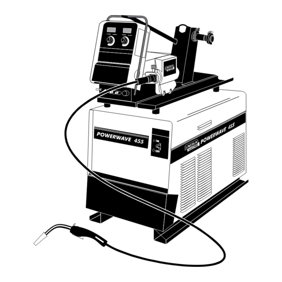
POWER WAVE 455/POWER FEED 10
For use with machines having Code Numbers:
Power Wave 455:
Power Feed 10:
10767, 10768, 10779, 10780, 10781, 10782, 10783
SERVICE MANUAL
SVM135-B
| Issue D ate 01, Jul
© Lincoln Global, Inc. All Rights Reserved.
NOTE: This manual will cover most of the troubleshooting and repair
procedures for the code numbers listed. Some variances may exist when
troubleshooting/repairing later code numbers.
10372, 10521, 10522, 10552, 10553, 10554, 10555
10435, 10436, 10437, 10438, 10493, 10494, 10760,
Need Help? Call 1.888.935.3877
to talk to a Service Representative
Hours of Operation:
8:00 AM to 6:00 PM (ET) Mon. thru Fri.
After hours?
Use "Ask the Experts" at lincolnelectric.com
A Lincoln Service Representative will contact you
no later than the following business day.
For Service outside the USA:
Email: globalservice@lincolnelectric.com
Advertisement
Chapters
Table of Contents
Troubleshooting


Need help?
Do you have a question about the 10372 and is the answer not in the manual?
Questions and answers