Table of Contents
Advertisement
Quick Links
Operator's Manual
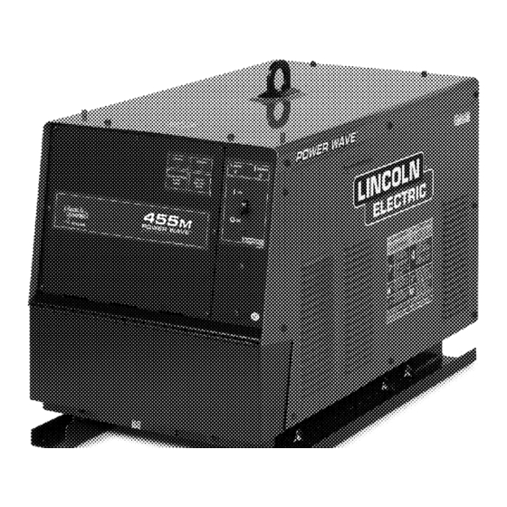
POWER WAVE
Register your machine:
www.lincolnelectric.com/register
Authorized Service and Distributor Locator:
www.lincolnelectric.com/locator
Save for future reference
Date Purchased
Code:
(ex: 10859)
Serial:
(ex: U1060512345)
IM762-E
| Issue D ate 13-Jan
© Lincoln Global, Inc. All Rights Reserved.
455M
®
For use with machines having Code Numbers:
10942, 11057, 11152, 11311, 11312,
11872, 11874, 11875, 11943
Need Help? Call 1.888.935.3877
to talk to a Service Representative
Hours of Operation:
8:00 AM to 6:00 PM (ET) Mon. thru Fri.
After hours?
Use "Ask the Experts" at lincolnelectric.com
A Lincoln Service Representative will contact you
no later than the following business day.
For Service outside the USA:
Email: globalservice@lincolnelectric.com
Advertisement
Table of Contents
Troubleshooting

Subscribe to Our Youtube Channel
Related Manuals for Lincoln Electric POWER WAVE455M


Summary of Contents for Lincoln Electric POWER WAVE455M
-
Page 1: Power Wave
Operator’s Manual POWER WAVE 455M ® For use with machines having Code Numbers: 10942, 11057, 11152, 11311, 11312, 11872, 11874, 11875, 11943 Register your machine: Need Help? Call 1.888.935.3877 www.lincolnelectric.com/register to talk to a Service Representative Authorized Service and Distributor Locator: Hours of Operation: www.lincolnelectric.com/locator 8:00 AM to 6:00 PM (ET) Mon. - Page 2 351040, Miami, Florida 33135 or CSA Standard W117.2-1974. A Free copy of “Arc Welding Safety” booklet E205 is available from the Lincoln Electric Company, 22801 St. Clair Avenue, Cleveland, Ohio 44117-1199. BE SURE THAT ALL INSTALLATION, OPERATION, MAINTENANCE AND REPAIR PROCEDURES ARE PERFORMED ONLY BY QUALIFIED INDIVIDUALS.
-
Page 3: Electric Shock Can Kill
SAFETY ARC RAYS can burn. ELECTRIC SHOCK can 4.a. Use a shield with the proper filter and cover kill. plates to protect your eyes from sparks and 3.a. The electrode and work (or ground) circuits the rays of the arc when welding or observing are electrically “hot”... - Page 4 SAFETY WELDING and CUTTING CYLINDER may explode SPARKS can if damaged. cause fire or explosion. 7.a. Use only compressed gas cylinders 6.a. Remove fire hazards from the welding area. containing the correct shielding gas for the If this is not possible, cover them to prevent process used and properly operating the welding sparks from starting a fire.
- Page 5 SAFETY PRÉCAUTIONS DE SÛRETÉ 6. Eloigner les matériaux inflammables ou les recouvrir afin de prévenir tout risque dʼincendie dû aux étincelles. Pour votre propre protection lire et observer toutes les instructions et les précautions de sûreté specifiques qui parraissent dans ce 7.
- Page 6 Electric for advice or information about their use of our products. We respond to our customers based on the best information in our posses- sion at that time. Lincoln Electric is not in a position to warrant or guarantee such advice, and assumes no liability, with respect to such infor- mation or advice.
-
Page 7: Table Of Contents
TABLE OF CONTENTS Page Installation .......................Section A Technical Specifications - POWER WAVE 455M ..........A-1 ® Safety Precautions....................A-2 Select Suitable Location ..................A-2 Lifting.......................A-2 Stacking ......................A-2 Machine Grounding ....................A-2 High Frequency Protection ..................A-2 Input Connection....................A-2 Input Fuse and Supply Wire Considerations ............A-3 Input Voltage Change Over Procedure..............A-3 Electrode and Work Cable Connections..............A-3 Cable Inductance, and its Effects on Pulse Welding ..........A-4... -
Page 8: Table Of Contents
TABLE OF CONTENTS Page Troubleshooting ....................Section E How to use Troubleshooting Guide ...............E-1 Using the Status LED to Troubleshoot System Problems ........E-2 Error Codes For Power Waves................E-3 Troubleshooting Guide................E-4 thru E-6 ________________________________________________________________________ Wiring Diagram ................Section F-1 thru F-3 Connection Diagrams ..................Section F-4 Dimension Print....................Section F-5 ________________________________________________________________________ Parts Lists ..................P-438, P-702 Series... -
Page 9: Installation
INSTALLATION TECHNICAL SPECIFICATIONS - POWER WAVE 455M (K2202-1, K2202-3) ® INPUT AT RATED OUTPUT - THREE PHASE ONLY INPUT VOLTS- OUTPUT INPUT IDLE POWER FACTOR EFFICIENCY CONDITIONS CURRENT @ RATED FREQUENCY @ RATED OUTPUT POWER OUTPUT AMPS AMPS / VOLTS / DUTY CYCLE 450A@38V.100% 58/53/25/22 208/230/460/575V - 60HZ. -
Page 10: Safety Precautions
INSTALLATION SAFETY PRECAUTIONS Read LIFTING this entire installation section before you start installa- Lift the machine by the lift bail only. The lift bail is tion. designed to lift the power source only. Do not attempt to lift the Power Wave with accessories attached to it. WARNING STACKING ELECTRIC SHOCK can kill. -
Page 11: Input Fuse And Supply Wire Considerations
INSTALLATION FIGURE A.1 - CONNECTION DIAGRAM ON CONNECTION/INPUT ACCESS DOOR INPUT SUPPLY CONNECTION DIAGRAM VOLTAGE = 200-208V W / L 3 WARNING 200-208V V / L 2 C R1 Disconnect input power before 220-230V inspecting or servicing machine. U / L1 Do not operate with covers 440-460V removed. -
Page 12: Cable Inductance, And Its Effects On Pulse Welding
INSTALLATION For additional Safety information regarding the elec- CABLE INDUCTANCE, AND ITS EFFECTS trode and work cable set-up, See the standard "SAFE- ON PULSE WELDING TY INFORMATION" located in the front of the For Pulse Welding processes, cable inductance will Instruction Manuals. -
Page 13: Power Wave To Semi-Automatic Power Feed Wire Feeder Interconnections
INSTALLATION Enable the voltage sense leads as follows: Electrode Voltage Sensing Enabling or disabling electrode voltage sensing is TABLE A.2 Process Electrode Voltage Work Voltage automatically configured through software. The 67 electrode sense lead is internal to the cable to the Sensing 67 lead * Sensing 21 lead wire feeder and always connected when a wire feeder... - Page 14 INSTALLATION CONFIGURING THE SYSTEM If a system can not be “Auto Mapped” then the status light on the power source will blink green fast and the welder output will be disabled. If a system is not For codes below 11100, consult the semi-automatic “Auto-mappable”, then consult the instruction manual Power Feed instruction manual for configuration...
-
Page 15: Alternate Hard Automatic Application
INSTALLATION ALTERNATE HARD AUTOMATIC APPLICATION (using a UI, WD Module, and PF-10R) ® POWER WAVE 455M PF-10R WIRE DRIVE MODULE (FH1) COMBINATION HARD AUTOMATION APPLICATION (w/ Semi-Auto, WD Module, and PF-10R) ® POWER WAVE 455M PF-10R WIRE DRIVE MODULE DUAL HEAD (FH1) System that is NOT "Auto Mappable"... -
Page 16: Welding With Multiple Power Waves
INSTALLATION WELDING WITH MULTIPLE POWER CONTROL CABLE SPECIFICATIONS WAVES ® It is recommended that genuine Lincoln control cables be used at all times. Lincoln cables are specifically designed for the communication and power needs of CAUTION the Power Wave / Power Feed system. -
Page 17: Multiple Arc Unsynchronized
INSTALLATION MULTIPLE ARC UNSYNCHRONIZED SENSE LEAD AND WORK LEAD PLACEMENT GUIDELINES POWER WAVE 455M ®... -
Page 18: I / O Receptacle Specifications
A-10 A-10 INSTALLATION I / O RECEPTACLE SPECIFICATIONS switch 7 auto mapping off(default) auto mapping enable TABLE 3 WIRE FEEDER RECEPTACLE S1 auto mapping disabled LEAD# FUNCTION Communication Bus L Communication Bus H switch 8 work sense lead Electrode Voltage Sense *off(default) work sense lead not connected 0vdc work sense lead connected... -
Page 19: Operation
OPERATION SAFETY PRECAUTIONS Read this entire section of operating instructions before operating the machine. WARNING ELECTRIC SHOCK can kill. • Unless using cold feed feature, when feeding with gun trigger, the electrode and drive mechanism are always elec- trically energized and could remain energized several seconds after the welding ceases. -
Page 20: Graphic Symbols That Appear On This Machine Or In This Manual
OPERATION GRAPHIC SYMBOLS THAT APPEAR ON THIS MACHINE OR IN THIS MANUAL SMAW INPUT POWER GMAW FCAW HIGH TEMPERATURE GTAW OPEN CIRCUIT MACHINE STATUS VOLTAGE CIRCUIT BREAKER INPUT VOLTAGE WIRE FEEDER OUTPUT VOLTAGE POSITIVE OUTPUT INPUT CURRENT NEGATIVE OUTPUT OUTPUT CURRENT PROTECTIVE 3 PHASE INVERTER GROUND... -
Page 21: Definition Of Welding Terms
OPERATION SMAW DEFINITION OF WELDING TERMS • Shielded Metal Arc welding NON-SYNERGIC WELDING MODES • Stud Arc Welding • A Non-synergic welding mode requires all welding process variables to be set by the operator. • Submerged Arc Welding SYNERGIC WELDING MODES SAW-S •... -
Page 22: General Description
OPERATION GENERAL DESCRIPTION DeviceNet Interface Module This module can be used for DeviceNet capability. It The Power Wave ® semi-automatic power source is will has a 5 pin sealed mini connector per ANSI designed to be a part of a modular, multi-process B93.55M-1981. -
Page 23: Case Front Controls
OPERATION FIGURE B.1 CASE FRONT CONTROLS All operator controls and adjustments are located on the case front of the Power Wave . (See Figure B.1) ® 1. POWER SWITCH: Controls input power to the Power Wave ® 2. STATUS LIGHT: A two color light that indicates system errors. -
Page 24: Nominal Procedures
1.000 is a good starting point for most condi- meet most needs. If a special welding program is tions. desired, contact the local Lincoln Electric sales repre- sentative. To make a weld, the Power Wave ®... -
Page 25: Constant Voltage Welding
OPERATION • WELDING MODE Non Synergic CV: May be selected by name (CV/MIG, CC/Stick Crisp, This type of CV mode behaves more like a conven- Gouge, etc.) or by a mode number (10, 24, 71, etc.) tional CV power source. Voltage and WFS are inde- depending on the Control Box options. -
Page 26: Pulse Welding
OPERATION PULSE WELDING The Power Wave ® utilizes "adaptive control" to com- pensate for changes in electrical stick-out while weld- ing. (Electrical stick-out is the distance from the con- Pulse welding procedures are set by controlling an tact tip to the work piece.) The Power Wave ®... -
Page 27: Accessories
ACCESSORIES OPTIONAL EQUIPMENT FACTORY INSTALLED Wire Drive Interface Module, K2205-1 FIELD INSTALLED Work Voltage Sense Lead Kit, K940 Dual Cylinder Undercarriage, K1570-1. Gas Guard Regulator, K659-1 Coaxial welding Cable, K1796 Cool Arc 40 K1813-1 (115VAC) Water Flow Sensor, K1536-1 Wire Drive Interface Module, K2205-1 DeviceNet interface Module, K2206-1 COMPATIBLE LINCOLN EQUIPMENT Any Arc-Link compatible semi-automatic wire feeding... -
Page 28: Maintenance
Generally speaking the machine calibration will not need adjustment. However, if the weld performance changes, or the yearly calibration check reveals a problem, contact the Lincoln Electric Company for the calibration software utility. The calibration procedure itself requires the use of a grid, and certified actual meters for voltage and cur- rent. -
Page 29: How To Use Troubleshooting Guide
HOW TO USE TROUBLESHOOTING GUIDE WARNING Service and Repair should only be performed by Lincoln Electric Factory Trained Personnel. Unauthorized repairs performed on this equipment may result in danger to the technician and machine operator and will invalidate your factory warranty. For your safety and to avoid Electrical Shock, please observe all safety notes and precautions detailed throughout this manual. - Page 30 TROUBLESHOOTING USING THE STATUS LED TO Included in this section is information about the power source Status LED, and some basic troubleshooting TROUBLESHOOT SYSTEM PROBLEMS charts for both machine and weld performance. The Power Wave ® / Power Feed ® are best diagnosed The STATUS LIGHT is a two color light that indicates as a system.
- Page 31 TROUBLESHOOTING Observe all Safety Guidelines detailed throughout this manual ERROR CODES FOR THE POWER WAVE ® The following is a list of possible error codes that the POWER WAVE 455M can output via the status light (see ® "Troubleshooting the Power Wave ®...
-
Page 32: Troubleshooting
40VDC supply. CAUTION If for any reason you do not understand the test procedures or are unable to perform the tests/repairs safely, con- tact your local authorized Lincoln Electric Field Service Facility for technical assistance. POWER WAVE 455M... - Page 33 570 Amps to 325 Amps. CAUTION If for any reason you do not understand the test procedures or are unable to perform the tests/repairs safely, con- tact your local authorized Lincoln Electric Field Service Facility for technical assistance. POWER WAVE 455M ®...
- Page 34 CAUTION If for any reason you do not understand the test procedures or are unable to perform the tests/repairs safely, con- tact your local authorized Lincoln Electric Field Service Facility for technical assistance. POWER WAVE 455M ®...
- Page 35 DIAGRAMS ENHANCED DIAGRAM POWER WAVE 455M ®...
- Page 36 DIAGRAMS ENHANCED DIAGRAM POWER WAVE 455M ®...
- Page 37 DIAGRAMS POWER WAVE 455M ®...
-
Page 38: Connection Diagram
CONNECTION DIAGRAM Connection Diagram Semi-automatic "Simple System" (Electrode Positive, CV/Pulse Configuration shown) ® POWER WAVE WIRE FEEDER WORK CONTROL CABLE K1543 POWER WAVE 455M ®... - Page 39 DIAGRAMS POWER WAVE 455M ®...
- Page 40 NOTES POWER WAVE 455M ®...
- Page 41 NOTES POWER WAVE 455M ®...
- Page 42 Do not touch electrically live parts or Keep flammable materials away. Wear eye, ear and body protection. WARNING electrode with skin or wet clothing. Insulate yourself from work and ground. Spanish No toque las partes o los electrodos Mantenga el material combustible Protéjase los ojos, los oídos y el AVISO DE bajo carga con la piel o ropa moja-...
- Page 43 Keep your head out of fumes. Turn power off before servicing. Do not operate with panel open or WARNING Use ventilation or exhaust to guards off. remove fumes from breathing zone. Spanish Los humos fuera de la zona de res- Desconectar el cable de ali- No operar con panel abierto o AVISO DE...
- Page 44 • World's Leader in Welding and Cutting Products • • Sales and Service through Subsidiaries and Distributors Worldwide • Cleveland, Ohio 44117-1199 U.S.A. TEL: 216.481.8100 FAX: 216.486.1751 WEB SITE: www.lincolnelectric.com...
Need help?
Do you have a question about the POWER WAVE455M and is the answer not in the manual?
Questions and answers