
Related Manuals for WAGNER ProSpray 3.21 0558019


Summary of Contents for WAGNER ProSpray 3.21 0558019
- Page 1 Operating manual ProSpray 3.21 Airless high-pressure spraying unit Models: 0558019 0558046 Original operating manual ProSpray 3.21 Edition 9 / 2014 0558 932J...
- Page 2 Before any work is done on the unit or for every break in work the following rules must be observed: 1. Release the pressure from spray gun and hose. 2. Secure the WAGNER spray gun using the safety catch on the trigger. 3. Switch off unit. Be safety conscious!
-
Page 3: Table Of Contents
Contents Contents Page Page Safety regulations for Airless spraying ........4 Remedy in case of faults ..............13 Explanation of symbols used .............. 4 Servicing ....................14 Electric Safety .................... 5 Electrostatic charging (formation of sparks or flames) ....5 10.1 General servicing ...................14 10.2 High-pressure hose................14 General view of application ............. -
Page 4: Safety Regulations For Airless Spraying
• Lay the high-pressure hose in such a way as to ensure that it cannot be tripped over. Danger of explosion from solvent, paint fumes and incompatible materials Only use WAGNER original-high-pressure hoses in order to ensure functionality, safety and durability. Danger of injury from inhalation of harmful vapors HAZARD: EXPLOSION OR FIRE Notes give important information which should Solvent and paint fumes can explode or ignite. -
Page 5: Electric Safety
Safety regulations Electric Safety • Follow material and solvent manufacturer’s warnings and instructions. Be familiar with the coating material’s MSDS Electric models must be earthed. In the event of an electrical short sheet and technical information to ensure safe use. circuit, earthing reduces the risk of electric shock by providing an • Use lowest possible pressure to flush equipment. escape wire for the electric current. -
Page 6: General View Of Application
WAGNER ProSpray units are electrically driven high-pressure spraying units. Viscosity A gear unit transfers the driving force to a crankshaft. The crankshaft moves the pistons of the material feed pump up and down. -
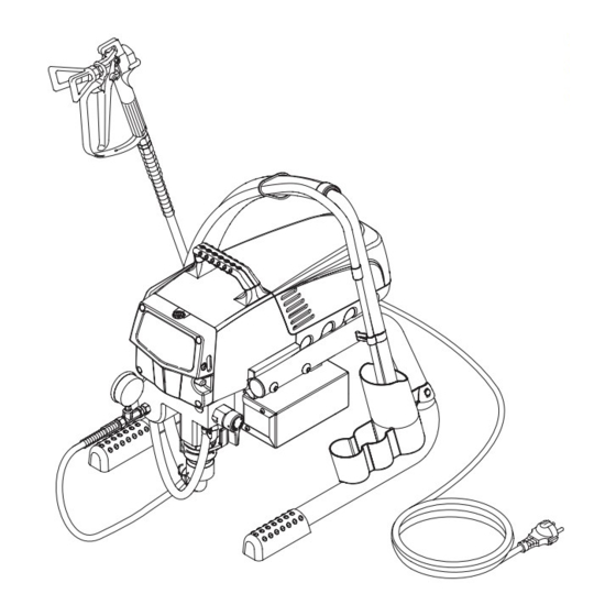
Page 7: Legend For Explanatory Diagram Prospray 3.21
Description of unit Legend for explanatory diagram ProSpray 3.21 3 Return hose 10 Oil level gauge 4 Suction hose 11 ON/OFF switch 5 Frame 12 Control panel indicators 6 Drip cup 13 Pressure control knob 7 Power cord 14 Oil cup for EasyGlide (EasyGlide prevents 8 Relief valve increased wear of the packings) Lever position vertical –... -
Page 8: Technical Data
Description of unit Starting operation Starting operation Technical data Voltage: 100-120 Volt , 50/60 Hz High-pressure hose, spray gun and separating Max. current consumption: 9.0 A Power cord: 3 x 1.5 mm – 6 m or 2.5 m 1. Screw the pressure gauge (1) to the coating material outlet Acceptance capacity: 900 Watt (Fig. -
Page 9: Control Panel Indicators
Starting operation Solid Green When the pressure indicator is solid green, the sprayer is operating between 12 MPa (120 bar) and 23 MPa (230 bar). A solid green pressure indicator means: • The sprayer is at the proper pressure setting for spraying oil- based and latex house paints • The sprayer is operating at peak performance at a high pressure setting • If the pressure indicator goes to solid yellow when the pressure is set so that it starts at solid green, it indicates one of the following:... -
Page 10: Cleaning Preserving Agent When Starting-Up Of Operation Initially
Starting operation Spraying technique Spraying technique Cleaning preserving agent when starting-up of operation initially 1. Immerse the suction tube (Fig. 6, Item 1) and return hose (2) Injection hazard. Do not spray without the tip guard into a container with a suitable cleaning agent. in place. -
Page 11: Handling The High-Pressure Hose
1. Remove suction hose from the coating material. Make sure that the high-pressure hose cannot twist. This can be 2. Close the relief valve, valve position SPRAY (p spray). avoided by using a Wagner spray gun with a swivel joint and a hose 3. Switch the unit ON. system. -
Page 12: Suction Filter
Cleaning the unit (shutting down) Suction filter Cleaning Airless spray gun 1. Rinse Airless spray gun with an appropriate cleaning agent. 2. Clean tip thoroughly with appropriate cleaning agent so that A clean suction filter always guarantees maximum no coating material residue remains. feed quantity, constant spraying pressure and problem-free functioning of the unit. -
Page 13: Remedy In Case Of Faults
Piston is worn. Remove and replace piston. Increased pulsation at the spray Incorrect high-pressure hose type. Only use WAGNER original-high-pressure hoses in order to ensure functionality, safety and durability. Tip worn or too large. Replace tip. Pressure too high. -
Page 14: Servicing
The risk of damage rises with the age of the high- 7. Remove the pusher stem clip and slide the pusher stem pressure hose. Wagner recommends replacing high- housing (7) from the inlet valve housing (1). pressure hoses after 6 years. -
Page 15: Packings
Repairs at the unit 11.3 Packings 1. Remove inlet valve housing in accordance with the steps in Chapter 11.2, Page 14. 2. It is not necessary to remove the outlet valve. 3. Unscrew both cylinder head screws (Fig. 13, Item 1) from the pump manifold (2) with a 3/8 inch hexagon socket head wrench. -
Page 16: Prospray 3.21 Connection Diagram
Repairs at the unit 18. Slide the top of the piston (3) into the T-slot (9) on the slider assembly (4). 19. Position the pump manifold (2) underneath the gear unit housing and push up until it rests against the gear unit housing. -
Page 17: Appendix
Appendix Appendix 12.1 Selection of tip To achieve faultless and rational working, the selection of the tip is of the greatest importance. In many cases the correct tip can only be determined by means of a spraying test. Some rules for this: The spray jet must be even. -
Page 18: Airless Tip Table
Airless tip table WAGNER without tip without tip Trade Tip 2 F thread (11/16 - 16 UN) G thread (7/8 - 14 UN) up to 270 bar for Wagner spray guns for Graco/Titan spray guns (27 MPa) Order no. 0556 042 Order no. 0556 041 Application Tip marking Spray angle... -
Page 19: Pump-Runner
Appendix 12.5 Pump-Runner (Order No. 2306987) Universal accessories for cleaning, clean transportation and preservation of the pump unit. Features: • Simpler cleaning – the cleaning liquid circulates constantly through the pump making thorough cleaning of the interior • No cleaning necessary during work stoppage or change of location because the paint in the pump cannot dry out or leak • Better protection • Simple assembly Suitable for the following models: Diaphragm Pumps Double-stroke piston pumps SF 21 Finish 270/370 PS 24 PS 3.25 SF 23 Nespray Deco PS 26 PS 3.29 SF 27 Nespray 31... - Page 20 Accessories illustration ProSpray 3.21 ProSpray 3.21...
- Page 21 Item Part No. Description 0296 388 Spray gun AG 08, F-thread 0296 386 Spray gun AG 08, G-thread 0502 166 Spray gun AG 14, F-thread 0502 119 Spray gun AG 14, G-thread 0296 441 Pole gun 120 cm, G-thread 7/8” 0296 443 Pole gun 120 cm, F-thread 11/16” 0296 442 Pole gun 200 cm, G-thread 7/8”...
-
Page 22: Accessories For Prospray 3.21
Spare parts list ProSpray 3.21 Main Assembly BS4343 NEMA 5-15P 0558 466 0290 281 ~110V ~120V 2.5 m ProSpray 3.21... - Page 23 Item Part No. Description Item Part No. Description 0290 230 Motor shroud 0290 205 Pusher assembly (includes item 49) 9805 403 Set screw 0508 553 Screw (2) 9810 103 9800 319 Screw 0524 353 0551 757 Transducer jumper 9800 319 Screw (2) 9822 624 Washer (2)
-
Page 24: Spare Parts List For Fluid Section
Spare parts list ProSpray 3.21 Fluid section Item Part No. Description 0509 594 Retainer 0509 584 Piston guide ------- Upper packing 0551 756 Transducer assembly 0507 517 Pipe plug 0290 209 Pump manifold 0509 873 Fitting ------- Lower packing 0552 489 Bushing 0290 277 Piston rod... -
Page 25: Spare Parts List For Drive Assembly
Spare parts list ProSpray 3.21 Drive Assembly Item Part No. Description 0524 637A Housing assembly 0509 121 2nd stage gear 0558 373 Motor assembly, 120V (includes items 5-7) 9800 319 Screw (4) 0522 018 Capacitor assembly 0290 217 Baffle assembly 0512 340 0551 714 Cord grip (2)* 0558 449 Bracket*... -
Page 26: Spare Parts List Of Frame
Spare parts list ProSpray 3.21 Stand Suction system Item Part No. Description Item Part No. Description 9805 367 Screw (3) 0551 706 Siphon hose 0290 215 Drip cup 9850 638 Tie wrap (2) 0290 211 Leg, right 0558 659A Return tube 0294 635 Plug 0279 459... -
Page 27: Important Notes On Product Liability
If the user applies outside accessories and spare parts, the manufacturer´s liability can fully or partially be inapplicable; in extreme cases usage of the entire device can be prohibited by the competent authorities (employer´s liability insurance association and factory inspectorate division). Only the usage of original WAGNER accessories and spare parts guarantees that all safety regulations are observed. 3+2 years guarantee for professional finishing Wagner professional guarantee (Status 01.02.2009) -
Page 28: Sales And Service Companies
Wagner or one of our dealers will take back your used Wagner waste electrical or electronic equipment and will dispose of it for you in an environmentally friendly way. Please ask your local Wagner service centre or dealer for details or contact us direct. ProSpray 3.21...
Need help?
Do you have a question about the ProSpray 3.21 0558019 and is the answer not in the manual?
Questions and answers