Table of Contents
Advertisement
Quick Links
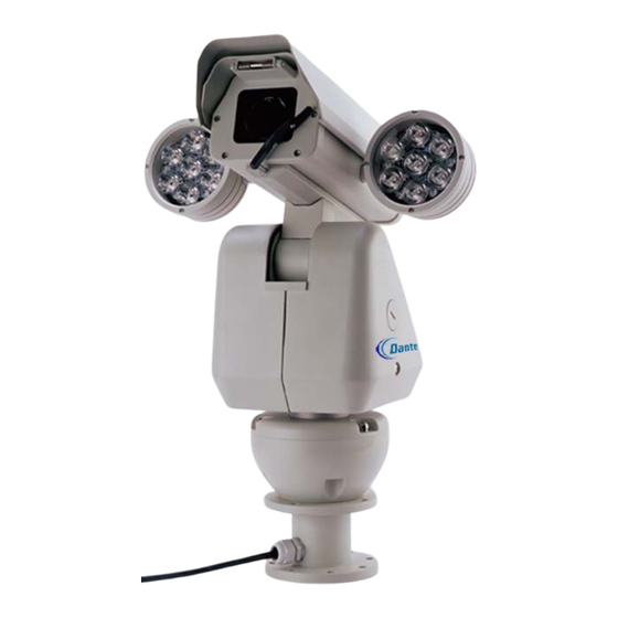
DLM1771-DLM1772(Y)-DLM1775(Y)
Integrated Camera Positioning
w/Optional Dual IR Lamps
Installation and Operations Manual
Model Number: DLM1771, DLM1772, DLM1775,
Description: Integrated Camera Positioning System
DLM1772Y, DLM1775Y
with optional dual IR Lamps, Heater,
Wiper and Day/Night 18x, 23x, 26x, 30x,
35x and 36x Zoom
Advertisement
Table of Contents

Related Manuals for Dante DLM1771


Summary of Contents for Dante DLM1771
- Page 1 DLM1771-DLM1772(Y)-DLM1775(Y) Integrated Camera Positioning w/Optional Dual IR Lamps Installation and Operations Manual Model Number: DLM1771, DLM1772, DLM1775, DLM1772Y, DLM1775Y Description: Integrated Camera Positioning System with optional dual IR Lamps, Heater, Wiper and Day/Night 18x, 23x, 26x, 30x, 35x and 36x Zoom...
-
Page 2: Table Of Contents
6.10 Auxiliary (Wiper and IR Lamp) 6.11 Reset Camera 6.12 Washer/Wiper Function and Wiper Controls 6.13 Menu for DLM1771 with Hitachi 1/3” CCD 18x D/N Camera 7. Dip Switch Settings 7.1 Pan Tilt Controls 7.2 Switch SW1 Protocols, Camera Modules, Baud Rate Settings 7.3 Switch SW2 Receiver/Driver Settings (P and D Protocols) -
Page 3: Installation
1. INSTALLATION MANUAL 1.1 FOREWORD This manual introduces the function, installation and operation of the integrated high speed pan tilt camera in details. Please thoroughly familiarize yourself with the information in this manual prior to installation. This series pan tilt camera is specially designed for airports, homeland security, customs, highway etc. -
Page 4: Safeguards And Warnings
1.3 SAFEGUARD AND WARNINGS Prior to installation and use of this product, please note the following WARNING. This product may be only used in specified range in order to avoid any damage or danger. Installation and servicing should only be done by qualified service personnel; It may not be used in temperature range, humidity and power supply outside the specifications. -
Page 5: Function Descriptions
1.3.2 FUNCTION DESCRIPTIONS Screen menu function (OSD) It has screen menu function. All information of camera and pan& tilt may be displayed by menu and to set the function and parameter Multi-camera control function Select different camera only by mending dial switch setting, no any hardware or software needed. - Page 6 image changes to black& white one in low LUX; black & white image changes to color one in high LUX (related to camera) Auto focus The camera automatically adjusts lens focus to keep clear image if auto focus mode. Manually operate FAR or NEAR focus adjustment may also adjust focus. The dome camera will recover auto focus adjustment function if operate horizontal, vertical rotation or control lens zoom.
-
Page 7: Preparation For Installation
2.2. PREPARATION FOR INSTALLATION 1) All electric working must be accorded to latest electric, fire proof and related specifications 2) Be sure all accessories are included as packing list and application and installation requirements. If not, please contact with supplier. 3) Be sure the product is suitable for the working environment. -
Page 8: Pedestal Installation
3.1 PEDESTAL INSTALLATION The pedestal installation camera includes the following parts. Inspect each package to make sure all parts are present. 3.1.1 Equipment List Integrated pan tilt Power Supply Box Pedestal mount Integrated pan tilt 1 pc pedestal 1 pc wall bracket 1 pc connecting cables... -
Page 9: Installation Instructions
3.1.2 INSTALLATION INSTRUCTIONS STEP 1 Locate the floor or impending base level that may support 4 times the weight of pan tilt. Fix the screws provided on the floor or firm surface. STEP 2 fix the pedestal on the floor or impending base level:... -
Page 10: Wiring Diagram
STEP 3 Install power supply, video output, RS-485 control input wiring through waterproof connector plugs, and connect them to the corresponding power supply, video, RS-485 wiring of the cable provided. Connect the cable according to the following pinout diagram: STEP 4 Fix the four Φ5x10 fixed screws on the pedestal, then install the connecting cable into the pedestal and screw it with waterproof BNC plugs. - Page 11 STEP 5 Loosen the screw nut cover on the pan tilt’s left side, to expose the 8 DIP dial switch. Set the protocol, baud rate, address for the pan tilt. Screw the nut cover tightly after completion of settings. STEP 6 Turn on the power to check operation.
- Page 12 DLM177x Pedestal Mount...
-
Page 13: Wall Installation
3.2 WALL INSTALLATION The wall installation camera contains following parts. Inspect each package to make sure all parts are present. 3.2.1 Equipment List Integrated Pan Tilt Wall Bracket Power Supply Box Integrated pan tilt 1 pc pedestal 1 pc wall bracket 1 pc connecting cables 1 pc... -
Page 14: Installation Instructions
3.2.2 Installation Instructions STEP 1 Install the Φ8mm screws on the wall (refer to the following picture) STEP 2 Install the power supply box on the wall if power supply box is required, then install the wall bracket on the power supply box. If no power supply enclosure is needed, install the bracket directly on the wall. -
Page 15: Wiring Diagram
STEP 3 Install power supply, video output, RS-485 control input wiring through the body of the bracket and connect them to the corresponding power supply, video, RS-485 wiring of the cable provided. Connect the cable according to the following pinout diagram: STEP 4 Connect the cables. - Page 16 STEP 5 Loosen the screw nut cover on the pan tilt’s left side, to expose the 8 DIP switch. Set the protocol, baud rate, address for the pan tilt. Screw the nut cover tightly after completion of settings. STEP 6 Turn on the power to check operation...
-
Page 17: Technical Parameters
4. TECHNICAL PARAMETERS 4.1 Structure parameters: Integrated pan tilt Aluminum alloy Rotating platform Aluminum alloy Load weight mode top bear standard Load weight Shield module with housing, defrost device, heater and fans installation wall mount, pedestal mount bracket requirement 4 times of the pan tilt’s weight operating temperature -40ºC ~ 50ºC Dimension... -
Page 18: Mechanical Diagram
Installation dimensions (no IR Lamps): DLM1771-DLM1772-DLM1775 Installation dimensions with LED IR Lamps front view dimensions w/ IR (LED) side view dimension diagram Installation dimensions with Laser IR Lamps front view dimensions w/ IR (Laser) side view dimension diagram... -
Page 19: Rotating Parameters
4.2 Rotating parameters: Pan rotation 360ºcontinuous rotation Tilt rotation +35º ~ -85º unobstructed rotation Manual control speed 0.1º ~ 100º/Second manual operation Tilt 0.1º ~ 80º/Second manual operation Preset speed 80º/ Second Tilt 40º/Second 4.3 Electrical parameters Input voltage 18VAC, 24VDC, 230VAC, 50/60Hz Input power 50W;... -
Page 20: Camera Parameters
4.4 Camera, lens parameters DLM1771 - 18X Day/Night Camera Specifications Image Sensor 1/3” Hitachi CCD Resolution 540 TVL TotalPixels NTSC 380k / PAL 470k Signal Format NTSC/PAL Video Output 1V p-p (sync negative) Lens 18X optical Focal Length f=4.7mm(Wide)~84.6mm(Tele) Aperture F1.6~F2.8... -
Page 21: Ir Lamp Parameters
4.5 IR Lamp Parameters >100m Distance Angle 45º IR Lens two pair 7x1W,6 x Φ8 IR lamps conversion efficiency wavelength 850nm Voltage 12VDC Current 2 x 1A Power 2 x 12W Measurement(L×W×H) two units of Φ108× 85mm Net Weight 2 x 0.5kg Method of operation 1: 1. -
Page 22: Operation
5. OPERATIONS 5.1 BASIC DESCRIPTIONS After connecting wires as per instructions in previous section and turning on power, the pan tilt camera will display its configured information. And after initialization, the menu will show “configure OK” information. If the user sets the POWER UP DONE, the camera will execute this movement and the initial screen disappears;... -
Page 23: Operation Procedures
NOTE: 1. VERSION 1.8 is the software version number of the P/T camera, and it will change as the product’s upgrade. 2. PROTOCOL is PTZ control type - supports P, D protocols, and it will change as the dip switch chooses different protocol. 3. -
Page 24: Preset Functions
PATTERN press pattern scan setting to start run the camera as the designed route press pattern scan setting to stop run the pattern scan, the camera will run the recorded route 5.3 Preset Functions The following stipulations are for presetting, Preset() function 1 to 8... -
Page 25: Ptz Functions
5.5 PTZ FUNCTIONS This series high-speed P/T camera manual pan speed 0.1 º -100 º/second, manual tilt speed 0.1º ~ 80º/second. Pan/tilt speed and lens zoom is proportional, darker the lens zoom, slower the speed is! The current position of P, T, Z three orientations (presetting positions) may be stored and repeat use. - Page 26 5.6.9 Low lux (color / black & white) function The camera automatically changes CCD lux according to surrounding light. Color image changes to black & white in low lux; black & white image changes to color in high lux (camera dependent) 5.6.10 Auto focus The camera automatically adjusts lens focus to keep clear image if auto focus mode.
-
Page 27: Menu Operation Instructions
Press key 94+ PRESET to exit pan tilt camera menu 6.1 MENU OPERATIOS INSTRUCTIONS The DLM1771-DLM1772-DLM1775 series P/T camera system is set by default to P/D protocol. Use preset position No.95 to open the main menu. For other protocols, please refer to protocol instruction. -
Page 28: Camera Menu
6.2 MAIN NENU PAN/TILT CAMERA 〈SYSTEM INFORMATION 〉 〈SYSTEM INFORMATION〉 〈CAMERA 〉 〈CAMERA 〉 〈PAN/TITL 〉 〈PAN/TITL 〉 〈POWER UP〉 〈POWER UP〉 〈PRIVACY ZONE〉 〈PRIVACY ZONE〉 〈ALARM〉 〈ALARM〉 〈AUX 〈AUX〉 RESET CAMERA RESET CAMERA EXIT EXIT 6.3 THE SECOND MENU I 6.3.1 System information menu SYSTEM INFORMATION... - Page 29 NOTE: The function of stabilizer and WDR will depends on the module function, if the function shows in the menu; it means the function is available. AUTO FOCUS Default Setting: ON FOCUS MODE: ON and OFF ZOOM LIMIT Default Setting: X26 Zoom Limit is show different limitation with different camera ZOOM SPEED Default Setting: 5...
-
Page 30: Pan/Tilt Menu
SHUTTER MODE Default Setting: AUTO Shutter Mode: AUTO and MAN SHUTTER SPEED Default Setting: 1/50 When shutter speed under the circumstances of MAN, 1/1~1/10000 may be selected, which is according to the camera parameter. AGC MODE Default Setting: AUTO AGC MODE: Auto and MAN GAIN Default Setting: 2db Gain Level may be selected between 0~28... -
Page 31: Initialization (Powering Up)
PARK TIME Default Setting: 30minutes Park Time: 2~60 min selectable PRESET TOUR TIME Default Setting:5s Preset tour time: 5~60 min selectable SCAN SPEED Default Setting: 10d/s Scan Speed: 1 d/s~40 d/s selectable MANUAL STOPS Default Setting: OFF Manual Stops Mode: ON and OFF SCAN STOPS Default Setting: OFF Manual Stops Mode: ON and OFF... -
Page 32: Privacy Zone
6.8 PRIVACY ZONE MENU Note: only the items with privacy function may enter this menu. SONY series module: PRIVACY ZONE PRIVACY NO PRIVACY NO SET DISPLAY SET DISPLAY WIDTH WIDTH HEIGHT COLOR HEIGHT BLACK COLOR TRANSPARENCY TRANSPARENCY PRESET 64 ALLOW PRESET 64 ALLOW PRESET 1 ALLOW... - Page 33 When it is ON, and it is in the status of non-menu, the all privacy zone will be open when setting 64 preset; and closed when using 64 preset. This kind of function is for the open and close of the whole privacy. PRESET 1 ALLOW default setting is:OFF PRESET 1 ALLOW has “ON”...
-
Page 34: Alarms
ALARM ALARM 6.9 ALARM INPUT NONE ALARM ALARM 1 NONE ALARM 2 BACK BACK default setting is :NONE ALARM 1(ALARM INPUT 1) ALARM INPUT 1 may choose NONE, 1PRESET~8PRESET, SCAN, PRETOUR, PATTERN ALARM 2 (ALARM INPUT 2) default setting is:NONE ALARM INPUT 2 may choose NONE, 1PRESET~8PRESET, SCAN, PRETOUR, PATTERN 6.10 AUX CONTROL WIPER... -
Page 35: Menu For Dlm1771 With Hitachi 1/3" Ccd 18X D/N Camera
5 sec, then stop for 15 sec. It will not stop until it receives the control instruction for stop (using 78 preset or by press “1+OFF”). 6.13 DLM1771 Integrated PTZ Menu for HITACHI 18x Day/Night 1/3” CCD camera <CAMERA II>... -
Page 36: Dip Switch Settings
7. DIP SWITCH SETTING 7.1 Pan/tilt Controls Note: When one control bus controls several (more than 2) Pan/Tilt cameras, it needs a 120ohm resistance at +/- terminals Com RS-485 in the farthest end of pan tilt camera in order to ensure the normal work of control signal. 7.2 Switch setting for SW1 Note: Switch SW1 is used to set protocol, camera and baud rate SW1 setting... -
Page 37: Switch Sw2 Receiver/Driver Settings (P And D Protocols)
7.3 Switch setting for SW2 Note: Switch SW2 is used to set receiving address. Protocol P addresses setting: Switch setting Address SW2- SW2- SW2- SW2- SW2- SW2- SW2- SW2- ----- ---- ---- ---- ----- ---- ---- ---- ----... - Page 38 Protocols D address setting: Switch setting Address SW2-1 SW2-2 SW2-3 SW2-4 SW2-5 SW2-6 SW2-7 SW2-8 ---- ---- ---- ---- ---- ---- ---- ----...
-
Page 39: Appendix A Troubleshooting
Appendix A TROUBLESHOOTING 1. Image Problem: No image displayed on monitor? →First check if the power supply wire connection, voltage, indicator and P/T camera work well, and then check the video wires, or it may be a problem with the cam module. Problem: Image becomes black after self check, but may be controlled →Control system may have changed the camera iris parameters. -
Page 40: Installation
→DVR control protocol is not compatible with the product or the function is not complete. Problem: why does the same pan tilt have different control speeds at different hard disk video recorder? →Speed command codes in control software of DVR are different. Problem: DVR may not control speed of pan tilt →Control command code of control software in DVR only has a fixed speed.
Need help?
Do you have a question about the DLM1771 and is the answer not in the manual?
Questions and answers