Table of Contents
Advertisement
Advertisement
Table of Contents

Related Manuals for Latronics PVE1200


Summary of Contents for Latronics PVE1200
-
Page 1: Instruction Manual
INSTRUCTION MANUAL INVERTER WITH ENERGY METER Doc No A340-D05-V22-Q2 03/12... - Page 2 WELCOME Latronics products are all proudly designed, engineered and manufactured in Australia. As a specialist sine wave inverter company we produce Inverters for a diverse range of applications such as; mining, railways, telecommunications, marine, remote power, motor homes, and other industrial or commercial installations.
-
Page 3: Table Of Contents
TABLE OF CONTENTS PAGE INSTALLATION DC WIRING / DC EARTHING AC WIRING WIRING DIAGRAMS INVERTER OPERATION SPECIAL FEATURES DIP SWITCH SETTINGS SOLAR INPUT CONFIGURATION FAULT FINDING RADIO FREQUENCY INTERFERENCE WARRANTY CONDITIONS TECHNICAL SPECIFICATIONS DECLARATION OF CONFORMITY... -
Page 4: Installation
Directive 2004/108/CE (EMC directive), Directive 2006/95/CE (low Voltage ambient temperature will not exceed rated values. Directive) If the PV Edge is to be installed outdoors, please use the Latronics Outdoor Date that CE marking was first affixed 2007 Enclosure (Part no: OE) The Inverter can be mounted horizontal on table or floor. -
Page 5: Dc Wiring / Dc Earthing
140VDC Mode) If other sources of DC input are required e.g. wind turbines, micro hydro Automatic Turn ON (Battery turbines etc. A battery bank or Latronics Turbine Controller (see pg 9) will 54VDC 108VDC mode) be required with the Maximum Power Point Tracking (MPPT) disabled Starting Operation (see pg 13). - Page 6 The Limited warranty periods of this inverter is 5 years. In all circumstances Latronics products are guaranteed from the date of purchase. case. To assemble the connecting partner, take the SBS50 connector and follow the instructions below.
-
Page 7: Ac Wiring
AM radio and in unusual cases may interfere with TV reception. the DC inputs and earth connections. Over the years Latronics has continued to invest significant time and effort in Latronics Inverters have the AC output (active and neutral) floating with the reduction of RFI related emissions from the entire product range, so that respect to the DC and Earth. -
Page 8: Fault Finding
FAULT FINDING 6. Connect the Active, Neutral and Earth cables as per diagram below. Should the Inverter appear to be malfunctioning we suggest the following to eliminate any external problems. Socket Turn the Inverter OFF by switching the External DC and AC isolators OFF. -
Page 9: Wiring Diagrams
SOLAR INPUT CONFIGURATION To configure your panels with the PV Edge inverter p lease go to http://www.latronics.com.au/products/grid-connect-inverter-pv-edge-series The DC input is suitable for connection to solar modules only, when MPPT is enabled. Do not exceed recommended Maximum DC Input Power. -
Page 10: Dip Switch Settings
This is required when the DC input is Photovoltaic Solar Modules only. In the OFF position the Maximum Power Point Tracking is disabled and the voltage tracking will operate at a fixed voltage of 54V (PVE1200) or 108V (PVE2500). This setting is required in a system where a 48V (PVE1200) or 96V (PVE2500) Battery Bank is required on the DC input. -
Page 11: Special Features
Note: The Solar inputs of multiple unit Inverters are not to be parallelled unless used with a battery. Please contact Latronics for more details. Maximum Power Point Tracking The optimum power level from the solar input depends on the available solar modules. -
Page 12: Inverter Operation
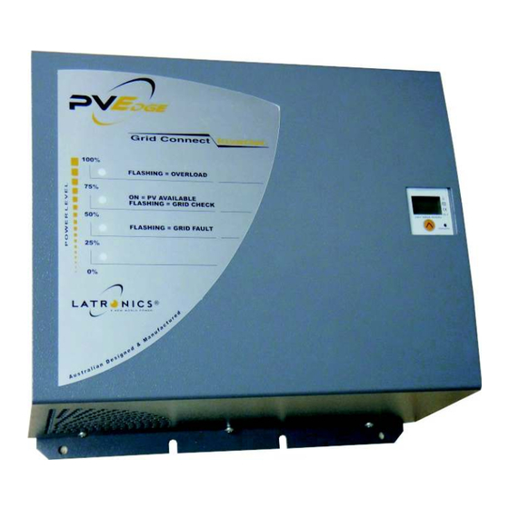
INVERTER OPERATION Indicator Lamps When the Inverter is switched on all 4 LED'S light up for 1 second while the The 4 LED’s on the front panel are dual purpose. microprocessor performs a start up and system check procedure. When in normal run mode they operate as a bar graph LED 4 -76%-100% (top Led).
Need help?
Do you have a question about the PVE1200 and is the answer not in the manual?
Questions and answers