
Related Manuals for Latronics PV Edge Grid Connect


Summary of Contents for Latronics PV Edge Grid Connect
-
Page 1: Instruction Manual
® N E W W O R L D P O W E R INSTRUCTION MANUAL WARRANTY REGISTRATION CARD... - Page 2 If your Inverter requires service or repair please complete the Warranty Repair Form on page 20. LATRONICS PO BOX 73 MOFFAT BEACH Q 4551 PH: 61 7 5491 6988 FAX: 61 7 5491 6792 EMAIL: technical@latronics.com WEB: www.latronics.com Copyright Latronics. Doc No M70 08/08 Version 5...
-
Page 3: Table Of Contents
Have you disconnected the battery, then tried to turn on your Inverter? WARRANTY CONDITIONS Please call *61 7 5491 6988 or email technical@latronics.com to obtain the address of your nearest service center and your RMA Number which is TECHNICAL SPECIFICATIONS essential for efficient processing. -
Page 4: Installation
INSTALLATION STATEMENT OF QUALITY ASSURANCE Grid Interactive Solar Systems have become increasingly popular in recent years. These systems do not necessarily require batteries for storage and The whole of the supplies have been subjected to the Quality therefore can have a very simple configuration. System Requirements in accordance with the conditions of AS/NZS ISO 9002: 1994. -
Page 5: Dc Wiring / Dc Earthing
If other sources of DC input are required e.g wind turbines, micro hydro Reverse Polarity Short Circuit Diode Across Short Circuit Diode Across turbines etc, a battery bank or Latronics Turbine Controller (see pg 9) will Protection DC Input Terminals DC Input Terminals... -
Page 6: Warranty Conditions
1. Strip back 10mm of cable (Recommended Cable: 6sqmm or bigger). goods or of acquiring equivalent goods. Latronics shall not be liable in any way whatsoever for indirect or consequential loss or damage whatsoever (whether 2. -
Page 7: Ac Wiring
AM radio and in unusual cases may interfere with TV reception. connections. Over the years Latronics has continued to invest significant time and effort in Latronics Inverters have the AC output (active and neutral) floating with the reduction of RFI related emissions from the entire product range, so that respect to the DC and Earth. -
Page 8: Fault Finding
FAULT FINDING 6. Connect the Active, Neutral and Earth cables as per diagram below. Should the Inverter appear to be malfunctioning we suggest the following to eliminate any external problems. Socket Turn the Inverter OFF by switching the DC & external AC Circuit Breakers OFF. -
Page 9: Wiring Diagrams
SOLAR INPUT CONFIGURATION PVE 1200 (Max Solar Input: 1400Wp) No. of Strings Number of Panels Panel Power Module Solar Input Per String At 25 C Type Power 1200W 1080W 100W 1200W 125W 1000W 140W 1120W 150W 1200W 165W 1320W 175W 1400W PVE 2500 (Max Solar Input: 2800Wp) Panel Power... -
Page 10: Dip Switch Settings
DIP SWITCH SETTINGS Switch 1 -MPPT / Battery mode In the ON position (default) the Maximum Power Point Tracking is enabled. This is required when the DC input is Photovoltaic Solar Modules only. In the OFF position the Maximum Power Point Tracking is disabled and the voltage tracking will operate at a fixed voltage of 54V (PVE1200) or 108V (PVE2500). -
Page 11: Special Features
SPECIAL FEATURES Circuit Breakers There is one double pole DC circuit breaker isolating both DC positive & DC negative. Digital KwH Meter The KwH meter shows an accumulative reading of the total power generated and allows the user to monitor their green power production. LCD display with 5 digits and 2 decimal places (i.e. -
Page 12: Inverter Operation
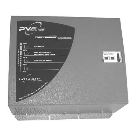
INVERTER OPERATION Indicator Lamps When the Inverter is switched on all 4 LED'S light up for 1 second while the The 4 lights on the front panel indicate the microprocessor performs a start up and system check procedure. Inverter power level in increments of 25% LED 4 -100% (top Led).
Need help?
Do you have a question about the PV Edge Grid Connect and is the answer not in the manual?
Questions and answers