Diamond DA20-C1 Maintenance Manual
Hide thumbs
Also See for DA20-C1:
- Maintenance manual (1372 pages) ,
- Flight manual (340 pages) ,
- Manual (269 pages)
Table of Contents
Advertisement
Quick Links
AIRCRAFT MAINTENANCE MANUAL
DA20-C1
Part III (Chapters 51 to 92)
DOC # DA201-C1
DIAMOND AIRCRAFT INDUSTRIES INC.
1560 CRUMLIN SIDEROAD, LONDON, ONTARIO
CANADA N5V 1S2
All rights reserved. No part of this manual may be reproduced or copied
in any form or by any means without written permission
of
DIAMOND AIRCRAFT INDUSTRIES INC.
Copyright © 2012 by DIAMOND AIRCRAFT INDUSTRIES INC., London, Ontario
Initial Issue: 19 Dec 97
REV 21
Revision 21: 14 Jan 13
Advertisement
Chapters
Table of Contents
Troubleshooting

Related Manuals for Diamond DA20-C1


Summary of Contents for Diamond DA20-C1
- Page 1 All rights reserved. No part of this manual may be reproduced or copied in any form or by any means without written permission DIAMOND AIRCRAFT INDUSTRIES INC. Copyright © 2012 by DIAMOND AIRCRAFT INDUSTRIES INC., London, Ontario Initial Issue: 19 Dec 97 REV 21...
- Page 2 This manual contains the maintenance information required by JAR-VLA. Contents and revision status can be found in the TABLE OF CONTENTS and the RECORD OF REVISIONS. DIAMOND AIRCRAFT INDUSTRIES INC. 1560 CRUMLIN SIDEROAD London, Ontario, Canada N5V 1S2 http://www.diamondair.com/ For more information contact: DIAMOND AIRCRAFT INDUSTRIES INC.
- Page 3 Standard Practices - Structures DA20-C1 AMM CHAPTER 51-00 STANDARD PRACTICES STRUCTURES DA201-C1 51-TITLE Page 1 30 Oct 09 Rev 16...
- Page 4 Standard Practices - Structures DA20-C1 AMM Intentionally Left Blank Page 2 51-TITLE DA201-C1 30 Oct 09 Rev 16...
-
Page 5: Table Of Contents
DA20-C1 AMM Standard Practices - Structures TABLE OF CONTENTS Subject CH-SE-SU Page STANDARD PRACTICES - STRUCTURES ....... 51-00-00 ..1 General. - Page 6 Standard Practices - Structures DA20-C1 AMM Intentionally Left Blank DA201-C1 Page 2 51-TOC Rev 21 14 Jan 13...
-
Page 7: Standard Practices - Structures
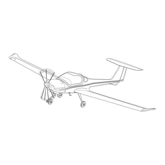
This chapter describes only the basic data about the structure. The DA20-C1 aircraft is a single-engine, low-wing monoplane of composite construction. It has a 'T' tail. It also has a fixed tricycle landing gear with a nose wheel that can caster. - Page 8 DA20-C1 AMM Standard Practices - Structures Figure 1 - Fuselage Restricted Area Diagram Page 2 DA201-C1 51-00-00 14 Jan 13 Rev 21...
-
Page 9: Design, Dimensions, Clearances And Wear Limits
Standard Practices - Structures DA20-C1 AMM Design, Dimensions, Clearances and Wear Limits Design Dimensions The detail drawing for the part shows the design dimensions. Use the design dimensions when manufacturing new parts or for a reconditioning scheme. Clearances and Wear Limits... - Page 10 DA20-C1 AMM Standard Practices - Structures LIMITED AREA 1 Repairs allowed on external skin damage up to 250mm (10 in) diameter LIMITED AREA 2 Repairs allowed on external skin damage up to 50mm (2 in) diameter PROHIBITED REPAIR AREA Repairs to be carried out only by...
-
Page 11: Inspection Techniques
Standard Practices - Structures DA20-C1 AMM Inspection Techniques There are different methods of inspecting a damaged composite area. The following gives the procedures for inspecting a damaged Fiber Reinforced Plastic (FRP) area. Examine Visually Look carefully at the outer surface of an area or component. If the paint has cracks or bubbles, then the composite may be damaged. - Page 12 DA20-C1 AMM Standard Practices - Structures Figure 3 - Wing, Top Fuselage and Horizontal Stabilizer Restricted Area Page 6 DA201-C1 51-00-00 14 Jan 13 Rev 21...
-
Page 13: Approved Materials And Suppliers
Standard Practices - Structures DA20-C1 AMM Approved Materials and Suppliers Resin and Hardner Supplier: Scheufler, D-70327 Stuttgart Resin: L160 (100 parts by weight) Hardener: 163 (28 parts by weight) Resin: L285 (100 parts by weight) Hardener: 286 (40 parts by weight) NOTE: L285/286 resin shall be used for DA20-C1S/N C0186 to S/N C0199. - Page 14 DA20-C1 AMM Standard Practices - Structures Approved Materials and Suppliers (Continued) Product Part Number/Description Manufacturer Supplier PVC Rigid Foam H060 Divinycell Divinycell Stochem 106 Summerlea Road Aerosil Aerosil 200 Brampton, ON, L6T 4X3, Canada Ashland Chemical Canada Microbaloons 10515 Rue Notre-Dame...
-
Page 15: Resin Handling
Standard Practices - Structures DA20-C1 AMM Product Part Number/Description Manufacturer Supplier Interior Texture Paint 1109-1240/4 Glasurit Material Paint SC80 Instrument Panel Hardener DH46 Flat Black BASF UNO-HD Reducer type dependant on Application Climate Paint N56582/T508 Clear Coat 432-0303 Hardener N39/1327... -
Page 16: Resin To Hardner Mixture
DA20-C1 AMM Standard Practices - Structures Procedure (1) Weigh the cut cloths and determine by ratio the resulting mixed resin weight. The ratio for glass fiber cloth to resin is: 100:70 and the ratio for carbon fiber cloth to resin is: 100:85. -
Page 17: Bonding Of Fiber Reinforced Plastics
Standard Practices - Structures DA20-C1 AMM Bonding of Fiber Reinforced Plastics Introduction The following steps establish the procedure for the bonding of precured fiber reinforced plastic parts. Materials Resin Resin Filler/Thickner (1) Scotchlite K20 (.19g/cc) Microballoons (2) AerosilFillerStochem (3) Cotton flocksCotton fibersQuarray Hill... -
Page 18: Curing
DA20-C1 AMM Standard Practices - Structures (1) Pre-fit the parts to be bonded to make sure that there is adequate clearance and mark out the exact bonding area between the parts as necessary for paste application. Note the gap between the parts. - Page 19 Standard Practices - Structures DA20-C1 AMM (4) Use a heat source with variable heat control to apply heat to the ambient air around the repair area. Do not point the heat gun directly at the composite material. Ensure that the nozzle of the heat gun is more than 12 inches away from the area being cured.
- Page 20 Standard Practices - Structures DA20-C1 AMM Intentionally Left Blank Page 14 DA201-C1 51-00-00 14 Jan 13 Rev 21...
-
Page 21: Control Surface Balancing
DA20-C1 AMM Standard Practices - Structures CONTROL SURFACE BALANCING General This section describes how to weigh and balance the control surfaces. Refer to Chapter 06-00 for values of weight and balance for each control surface. WARNING: YOU MUST WEIGH AND BALANCE A CONTROL SURFACE AFTER ANY WORK WHICH COULD AFFECT ITS WEIGHT OR BALANCE. - Page 22 Standard Practices - Structures DA20-C1 AMM Figure 1 - Rudder Static Balance 51-60-00 Page 2 DA201-C1 30 Oct 09 Rev 16...
- Page 23 DA20-C1 AMM Standard Practices - Structures Figure 2: Elevator Static Balance Figure 3 - Aileron Static Balance DA201-C1 51-60-00 Page 3 30 Oct 09 Rev 16...
- Page 24 Standard Practices - Structures DA20-C1 AMM Figure 4 - Flap Static Balance 51-60-00 Page 4 DA201-C1 30 Oct 09 Rev 16...
- Page 25 Doors DA20-C1 AMM CHAPTER 52-00 DOORS DA201-C1 52-TITLE Page 1 30 Oct 09 Rev 16...
- Page 26 DA20-C1 AMM Doors Intentionally Left Blank Page 2 52-TITLE DA201-C1 30 Oct 09 Rev 16...
- Page 27 DA20-C1 AMM Doors TABLE OF CONTENTS Subject CH-SE-SU Page DOORS ............52-00-00 ..1 General.
- Page 28 Doors DA20-C1 AMM Intentionally Left Blank DA201-C1 Page 2 52-TOC Rev 21 14 Jan 13...
-
Page 29: General
Doors DA20-C1 AMM DOORS General The DA20-C1 aircraft has two types of doors. The Canopy which gives access to the cockpit Access panels which give access to do maintenance. DA201-C1 52-00-00 Page 1 14 Jan 13 Rev 21... - Page 30 DA20-C1 AMM Doors Intentionally Left Blank Page 2 52-00-00 DA201-C1 14 Jan 13 Rev 21...
-
Page 31: Canopy
DA20-C1 AMM Doors CANOPY General The DA 20-C1 aircraft has a one-piece lifting canopy. It has a carbon-fiber reinforced plastic (CFRP) frame and one large acrylic transparency. The transparency has two small emergency windows. The canopy has a hinge at the back and a stabilizing rod on each side. The support arms have counterbalance springs to help operate the canopy. -
Page 32: Operation
DA20-C1 AMM Doors The latches with external handles are constructed as follows (Refer to Figure 202): The single steel plate is attached to the canopy frame by four steel screws and separated from the frame by two steel shims and an FRP spacer at each end. The shaft of the external handle is inserted into a bushing permanently installed in the steel plate. - Page 33 DA20-C1 AMM Doors Rear Hinge Balance Spring Acrylic Transparency Stabilizing Rod Right Canopy Latch (Shown Un-locked) Sliding Side Window Left Canopy Latch (Shown Un-locked) Outside Canopy Handle (Later Model Aircraft) Figure 1 - Canopy DA201-C1 52-10-00 Page 3 30 Oct 09...
- Page 34 Doors DA20-C1 AMM Intentionally Left Blank Page 4 52-10-00 DA201-C1 30 Oct 09 Rev 16...
-
Page 35: Canopy - Troubleshooting
DA20-C1 AMM Troubleshooting CANOPY - TROUBLESHOOTING General This table explains how to troubleshoot the canopy. If you find the trouble in column 1, do the repair given in column 3. TROUBLE POSSIBLE CAUSE REPAIR Canopy is difficult to move. Canopy frame damaged. - Page 36 DA20-C1 AMM Troubleshooting Intentionally Left Blank 52-10-00 Page 102 DA201-C1 30 Oct 09 Rev 16...
-
Page 37: Canopy - Maintenance Practices
DA20-C1 AMM Maintenance Practices CANOPY - MAINTENANCE PRACTICES General The following maintenance practices describe how to remove and install the canopy and how to do a canopy latch force test/adjustment. Remove/Install the Canopy CAUTION: TWO PEOPLE WILL BE NEEDED TO REMOVE/INSTALL THE CANOPY. THE CANOPY WILL BE DAMAGED IF YOU DROP IT. -
Page 38: The Canopy Latch Force Test
Maintenance Practices DA20-C1 AMM The Canopy Latch Force Test Equipment Item Quantity Part Number Strap Commercial Spring Scale Commercial The Canopy Latch Force Test - Canopies With Internal Handles Only Detail Steps/Work Items Key Items/References Close the canopy. Make sure both handles are fully forward. - Page 39 DA20-C1 AMM Maintenance Practices Detail Steps/Work Items Key Items/References Put a strap around the canopy grip at the top. Attach the spring scale to the strap. - Pull the spring scale straight aft - Measure and record the force necessary Force must be between 2.5 - 5 lbf...
-
Page 40: Adjust The Canopy Latch Force
Maintenance Practices DA20-C1 AMM Adjust the Canopy Latch Force Detail Steps/Work Items Key Items/References Release the screws which hold the strike block Refer to Figure 202. assembly to the fuselage. Lower the strike block assembly and install (or Shim, strike, P/N 22-5600-00-15 and remove) shims as necessary to give the P/N 22-5600-00-18. -
Page 41: Remove/Install The Sliding Side Window
DA20-C1 AMM Maintenance Practices Remove/Install the Sliding Side Window Remove the Sliding Side Window Detail Steps/Work Items Key Items/References Remove the air scoop lock as follows: Refer to Figure 203. - Remove the screw and the nut - Remove the two thin washers and a nylon washer - Remove the air scoop lock. - Page 42 Maintenance Practices DA20-C1 AMM Install the Sliding Side Window Detail Steps/Work Items Key Items/References Assemble the sliding window as follows: Refer to Figure 203. - Install the sliding window knob into the sliding window - Install the hinge block using two screws.
- Page 43 DA20-C1 AMM Maintenance Practices Hook Assembly Grip Stop Spacer Outer Side Plate Conical Washers Spring Pin Housing Inner Side Plate Adjusting Screw Roller Bearing Micro Switch Strike Assembly Shim Strike Block Pivot Pin Figure 201 - Canopy Latch Installation without Outside Handles...
- Page 44 Maintenance Practices DA20-C1 AMM Grip Cover Plate Guide Plate Hook Assembly Shim (s) Spacing Block Inner Side Plate Travel Limiting Screw Bronze Bushing (non-removable) Outside Handle Micro Roller Bearing Switch Strike Plate Shim Strike Assembly Pivot Pin Strike Block Figure 202 - Canopy Latch Installation with Outside Handles...
- Page 45 DA20-C1 AMM Maintenance Practices Figure 203 - Sliding Window Assembly Page 209 DA201-C1 52-10-00 30 Oct 09 Rev 16...
- Page 46 Maintenance Practices DA20-C1 AMM Intentionally Left Blank 52-10-00 Page 210 DA201-C1 30 Oct 09 Rev 16...
-
Page 47: Access Panels
ACCESS PANELS General The DA20-C1 aircraft has a small number of access panels. The panels give access for maintenance. Most panels are GFRP moldings. Self-tapping screws or camlock (quick-release) fasteners hold the panels. Refer to Chapter 71-10 for data about the engine cowlings. - Page 48 Doors DA20-C1 AMM Intentionally Left Blank Page 2 52-40-00 DA201-C1 30 Oct 09 Rev 16...
- Page 49 DA20-C1 AMM Fuselage CHAPTER 53-00 FUSELAGE DA201-C1 53-TITLE Page 1 30 Oct 09 Rev 16...
- Page 50 Fuselage DA20-C1 AMM Intentionally Left Blank Page 2 DA201-C1 53-TITLE 30 Oct 09 Rev 16...
- Page 51 DA20-C1 AMM Fuselage TABLE OF CONTENTS Subject CH-SE-SU Page FUSELAGE............53-00-00 ..1 General.
- Page 52 Fuselage DA20-C1 AMM Intentionally Left Blank DA201-C1 Page 2 53-TOC Rev 21 14 Jan 13...
- Page 53 Fuselage FUSELAGE General The DA20-C1 aircraft fuselage is a semi-monocoque structure. Two GFRP half-shells make the fuselage skin. GFRP frames and webs give strength and stiffness. Each half shell also makes the vertical stabilizer. The fuselage shells have many layers of glass cloth. Some areas have more glass cloth than other areas.
- Page 54 Fuselage DA20-C1 AMM Intentionally Left Blank Page 2 DA201-C1 53-00-00 14 Jan 13 Rev 21...
-
Page 55: Fuselage Structure
General This chapter describes the data about the fuselage structure. It also includes the vertical stabilizer. Refer to Chapter 51-00 for data about repair to the structure. The DA20-C1 aircraft has the following components in the fuselage structure: All of the main structural components are GFRP rigid moldings. Many layers of glass cloth bond together to make each molding. - Page 56 Fuselage DA20-C1 AMM Figure 1 - Fuselage Shells and Front Fuselage Structure 53-10-00 Page 2 DA201-C1 30 Oct 09 Rev 16...
- Page 57 DA20-C1 AMM Fuselage T-Panel The T-panel bonds to the inner-bottom skin of the fuselage behind the firewall. It gives strength and stiffness to the front fuselage. It has mountings for the nose landing gear. Floor The floor is a rigid GFRP molding. It bonds to the inner-bottom skin of the fuselage shell behind the firewall.
- Page 58 Fuselage DA20-C1 AMM Figure 2 - Front Fuselage Structure 53-10-00 Page 4 DA201-C1 30 Oct 09 Rev 16...
- Page 59 DA20-C1 AMM Fuselage Rollbar The rollbar is a rigid GFRP molding. Carbon tape gives strength and stiffness to the rollbar. The rollbar bonds to the inner face of the fuselage shell around the rear cockpit cut-out. Aft Control Bulkhead The aft control bulkhead is a rigid GFRP molding. The middle part has top and bottom flanges which hold the control bellcranks.
- Page 60 Fuselage DA20-C1 AMM Figure 3 - Rear Fuselage Structure 53-10-00 Page 6 DA201-C1 30 Oct 09 Rev 16...
- Page 61 DA20-C1 AMM Fuselage Vertical Stabilizer Upper Rib The vertical stabilizer upper rib is a rigid GFRP molding. It bonds to the fuselage shell at the top of the vertical stabilizer. It also bonds to the spar, vertical stabilizer. It has the mountings for the horizontal stabilizer.
- Page 62 Fuselage DA20-C1 AMM Figure 4 - Vertical Stabilizer Structure 53-10-00 Page 8 DA201-C1 30 Oct 09 Rev 16...
- Page 63 DA20-C1 AMM Maintenance Practices FUSELAGE - MAINTENANCE PRACTICES General The following maintenance practices describe how to do a high temperature paint repair of a cowling and in the area underside of the aircraft flight compartment, aft of the engine. High Temperature Paint Repair of a Cowling...
- Page 64 Maintenance Practices DA20-C1 AMM Detail Steps/Work Items Key Items/References Prepare the area(s) of the cowling for the For approved materials and suppliers, refer application of the high temperature paint, as to Chapter 51-00. follows: - If dirt or grease is present, wash the area with clean carbon tetrachloride or acetone.
- Page 65 DA20-C1 AMM Maintenance Practices Detail Steps/Work Items Key Items/References Apply the first coat of fire resistant paint with a For approved materials and suppliers, refer splatter spray gun, a brush or a roller to a to Chapter 51-00. minimum thickness of 0.010 in (250 microns).
- Page 66 Maintenance Practices DA20-C1 AMM Detail Steps/Work Items Key Items/References Apply the two cross coats to achieve the Film thickness: required thickness. For the first coat: 25 microns For the second coat: 35 microns. Total thickness: 60 microns (0.002 in or 2.3 mil)
- Page 67 DA20-C1 AMM Stabilizers CHAPTER 55-00 STABILIZERS DA201-C1 55-TITLE Page 1 30 Oct 09 Rev 16...
- Page 68 DA20-C1 AMM Stabilizers Intentionally Left Blank Page 2 DA201-C1 55-TITLE 30 Oct 09 Rev 16...
- Page 69 DA20-C1 AMM Stabilizers TABLE OF CONTENTS Subject CH-SE-SU Page STABILIZERS............55-00-00 ..1 General.
- Page 70 Stabilizers DA20-C1 AMM TABLE OF CONTENTS Subject CH-SE-SU Page RUDDER AND TAB ..........55-40-00 ..1 General .
- Page 71 STABILIZERS General The DA20-C1 aircraft has the usual stabilizers. The vertical stabilizer is part of the fuselage. The aft part of the left and right fuselage shells make the left and right shells of the vertical stabilizer. Refer to Chapter 53-10 for data on the fuselage structure.
- Page 72 DA20-C1 AMM Stabilizers Intentionally Left Blank 55-00-00 DA201-C1 Page 2 14 Jan 13 Rev 21...
-
Page 73: Horizontal Stabilizer
HORIZONTAL STABILIZER General The DA20-C1 aircraft has the usual horizontal stabilizer. The horizontal stabilizer attaches to the top of the vertical stabilizer. The elevator attaches to the trailing edge of the horizontal stabilizer. Refer to Chapter 55-20 for data about the elevator structure. - Page 74 Stabilizers DA20-C1 AMM Intentionally Left Blank Page 2 55-10-00 DA201-C1 30 Oct 09 Rev 16...
- Page 75 DA20-C1 AMM Maintenance Practices HORIZONTAL STABILIZER - MAINTENANCE PRACTICES General The following maintenance practices describe how to remove and install the horizontal stabilizer. Remove/Install the Horizontal Stabilizer Refer to Figure 201. Remove the Horizontal Stabilizer NOTE: Use 2 persons to remove/install the horizontal stabilizer.
- Page 76 Maintenance Practices DA20-C1 AMM Install the Horizontal Stabilizer Detail Steps/Work Items Key Items/References Put the horizontal stabilizer in position on the Use 2 persons. vertical stabilizer. Install the four mounting plate attaching bolts. Torque to 15.2 lbf-ft (20.6 Nm) Install the two bolts that connect the lower Torque to 4.6 lbf-ft (6.24 Nm).
- Page 77 DA20-C1 AMM Maintenance Practices Top Shell Outboard Elevator Hinges Center Elevator Hinge Aft Rib Forward Rib Rear Web End Rib Mount Plate Rigid Foam Core Hole For Access Bottom Shell To Hinge Nuts *Upper Mounting Bracket Cut-Out for Mounting Elevator Horn...
- Page 78 Maintenance Practices DA20-C1 AMM Intentionally Left Blank 55-10-00 Page 204 DA201-C1 01 Nov 10 Rev 17...
- Page 79 DA20-C1 AMM Stabilizers ELEVATOR General The DA20-C1 aircraft has the usual elevator. The elevator attaches to the rear web of the horizontal stabilizer. Refer to Chapter 27-30 for data about the elevator controls. Description Figure 1 shows the elevator structure.
- Page 80 Stabilizers DA20-C1 AMM Figure 1 - Elevator Structure 55-20-00 Page 2 DA201-C1 30 Oct 09 Rev 16...
- Page 81 DA20-C1 AMM Maintenance Practices ELEVATOR - MAINTENANCE PRACTICES General The following maintenance practices describe how to remove and install the elevator. Refer to Chapter 27-30 for adjustment data for the elevator control system. Remove/Install the Elevator Remove the Elevator NOTE: Use 2 persons to remove/install the elevator.
- Page 82 Maintenance Practices DA20-C1 AMM Detail Steps/Work Items Key Items/References Do a test for correct, full and free movement of Refer to Chapter 27-30. the elevator control. If necessary, adjust the elevator control. Install the horizontal stabilizer fairing. - Install the four screws.
-
Page 83: Lower Fin
DA20-C1 AMM Stabilizers LOWER FIN General The lower fin has three functions. It helps give directional stability. It makes a tail-bumper. It also has a tie-down point. Description Figure 1 shows the lower fin. The lower fin is a rigid GFRP molding. Five screws attach the lower fin to the bottom of the fuselage. - Page 84 DA20-C1 AMM Stabilizers Tie-Down Hole Lower Fin Attaching Screw Holes Figure 1 - Lower Fin 55-30-00 Page 2 DA201-C1 30 Oct 09 Rev 16...
- Page 85 DA20-C1 AMM Maintenance Practices LOWER FIN - MAINTENANCE PRACTICES General The following maintenance practices describe how to remove and install the lower fin. NOTE: If the lower fin is being replaced and the lower fin contains ballast: Measure weight of old lower fin;...
- Page 86 Maintenance Practices DA20-C1 AMM Intentionally Left Blank 55-30-00 Page 202 DA201-C1 30 Oct 09 Rev 16...
-
Page 87: Rudder And Tab
DA20-C1 AMM Stabilizers RUDDER AND TAB General The DA20-C1 aircraft has the usual rudder. The rudder attaches to the spar of the vertical stabilizer. Refer to Chapter 27-20 for data about the rudder controls. Description Figure 1 shows the rudder structure. - Page 88 Stabilizers DA20-C1 AMM Pivot Bushing Figure 1 - Rudder Structure 55-40-00 Page 2 DA201-C1 09 May 11 Rev 18...
- Page 89 DA20-C1 AMM Maintenance Practices RUDDER AND TAB - MAINTENANCE PRACTICES General The following maintenance practices describe how to remove and install the rudder. Refer to Chapter 27-30 for adjustment data for the rudder controls. Remove/Install the Rudder Remove the Rudder Figure 201 shows the rudder installation.
- Page 90 Maintenance Practices DA20-C1 AMM Remove/Install the Top Pivot Bushing Remove the Top Pivot Bushing Detail Steps/Work Items Key Items/References Remove the rudder from the aircraft Move the bottom of the rudder aft, then down to release the top pivot. Refer to Chapter 55-40-00.
- Page 91 DA20-C1 AMM Maintenance Practices Pivot Bushing Figure 201 - Rudder Installation Page 203 DA201-C1 55-40-00 09 May 11 Rev 18...
- Page 92 Maintenance Practices DA20-C1 AMM Intentionally Left Blank 55-40-00 Page 204 DA201-C1 09 May 11 Rev 18...
- Page 93 DA20-C1 AMM Windows CHAPTER 56-00 WINDOWS DA201-C1 56-TITLE Page 1 30 Oct 09 Rev 16...
- Page 94 Windows DA20-C1 AMM Intentionally Left Blank Page 2 DA201-C1 56-TITLE 30 Oct 09 Rev 16...
- Page 95 DA20-C1 AMM Windows TABLE OF CONTENTS Subject CH-SE-SU Page WINDOWS ............56-00-00 ..1 General.
- Page 96 Windows DA20-C1 AMM Intentionally Left Blank DA201-C1 Page 2 56-TOC Rev 21 14 Jan 13...
-
Page 97: General
Information on the principal canopy repair is given in this chapter. Description The DA20-C1 aircraft has a one-piece lifting canopy. It has a carbon-fiber reinforced plastic (CFRP) frame and one large acrylic transparency. The transparency has two small emergency windows. - Page 98 Windows DA20-C1 AMM Intentionally Left Blank Page 2 56-00-00 DA201-C1 14 Jan 13 Rev 21...
-
Page 99: Repair Of The Canopy Transparency
There is a crack stop drill hole in the shaded area, as shown in Figure 2. Otherwise you can use the following repair information. If in doubt, you must contact the aircraft manufacturer, Diamond Aircraft Industries Canada. Tools and Equipment... - Page 100 Windows DA20-C1 AMM 2.4 mm diameter Figure 1 - Temporary Repair Permanent Repair to the Canopy Transparency To make a permanent repair, do the following standard procedure: Detail Steps/Work Items Key Items/References If necessary, remove the canopy for the repair.
- Page 101 DA20-C1 AMM Windows Detail Steps/Work Items Key Items/References Use a high-speed grinder to cut a groove along Refer to Step 3 of Figure 3. the crack on the inner surface of the transparency. Make sure that it cuts into the first layer of filler.
- Page 102 Windows DA20-C1 AMM No Cracks are permitted in the shaded area. The maximum crack length is 150 mm (5.9 in). Figure 2 - Crack Limits 56-10-00 Page 4 DA201-C1 30 Oct 09 Rev 16...
- Page 103 DA20-C1 AMM Windows Figure 3 - Crack Repairs DA201-C1 56-10-00 Page 5 30 Oct 09 Rev 16...
- Page 104 Windows DA20-C1 AMM Figure 4 - Store-Drill Hole Repair 56-10-00 Page 6 DA201-C1 30 Oct 09 Rev 16...
-
Page 105: Replacement Of The Rear Window
Damage Limits The rear windows must be replaced when the crack is more than 2.0 in. (51 mm) long and the windows are damaged. Follow the following replacement information or contact the aircraft manufacturer, Diamond Aircraft Industries, Canada for assistance. - Page 106 Windows DA20-C1 AMM Replacement of the Rear Window Replace the rear window as follows: Detail Steps/Work Items Key Items/References CAUTION: WEAR MASK AND EYE PROTECTION WHEN GRINDING OUT EXISTING WINDOW. BE CAREFUL NOT TO DAMAGE THE SURROUNDING COMPOSITE STRUCTURE. Tape fuselage around the window with 2.0 in.
- Page 107 Windows DA20-C1 AMM Detail Steps/Work Items Key Items/References Remove all dust and debris from the bonding surfaces. Prepare bonding surface of the window and Use the wipe on wet/wipe off dry method. the fuselage by sanding with 320 grit paper.
- Page 108 Windows DA20-C1 AMM Detail Steps/Work Items Key Items/References Allow the caulk to cure overnight. Remove masking or flash tape. Mask off fuselage and window in preparation Refer to Chapter 51-00. for paint application. Paint to original line on fuselage and extend paint line to cover frame line on window.
- Page 109 DA20-C1 AMM Wings CHAPTER 57-00 WINGS DA201-C1 57-TITLE Page 1 30 Oct 09 Rev 16...
- Page 110 Wings DA20-C1 AMM Intentionally Left Blank Page 2 DA201-C1 57-TITLE 30 Oct 09 Rev 16...
- Page 111 DA20-C1 AMM Wings TABLE OF CONTENTS Subject CH-SE-SU Page WINGS ............57-00-00 ..1 General.
- Page 112 Wings DA20-C1 AMM Intentionally Left Blank DA201-C1 Page 2 57-TOC Rev 21 14 Jan 13...
-
Page 113: General
WINGS General The DA20-C1 aircraft has cantilever wings. The wings are set low on the fuselage. Each wing has a flap inboard on the trailing edge. There is an aileron on the outboard trailing edge. The wings are monocoque structure. Each wing has top and bottom shells. The shells have GFRP skins and a rigid foam core. - Page 114 Wings DA20-C1 AMM Intentionally Left Blank Page 2 DA201-C1 57-00-00 14 Jan 13 Rev 21...
-
Page 115: Wing Structure
WING STRUCTURE General The DA20-C1 aircraft has composite wings. The main spar has carbon fiber spar-caps. The wing shells have GFRP skins and a rigid foam core. Rigid GFRP moldings give strength to the structure. Some also hold control levers or bearings. - Page 116 DA20-C1 AMM Wings Root Rib The root rib has a forward part and an aft part. Both parts are rigid GFRP moldings with many layers of glass cloth. Many layers of glass cloth bond both parts of the root rib to the spar.
- Page 117 DA20-C1 AMM Wings Tie-Down Insert The tie-down insert gives strength to the tie-down point in the bottom shell. DA201-C1 57-10-00 Page 3 30 Oct 09 Rev 16...
- Page 118 DA20-C1 AMM Wings Figure 1 - Wing Structure - Shells, Spar, Root Rib and Webs 57-10-00 Page 4 DA201-C1 30 Oct 09 Rev 16...
- Page 119 DA20-C1 AMM Wings Figure 2 - Wing Structure - Ribs DA201-C1 57-10-00 Page 5 30 Oct 09 Rev 16...
- Page 120 Wings DA20-C1 AMM Intentionally Left Blank Page 6 57-10-00 DA201-C1 30 Oct 09 Rev 16...
-
Page 121: Wing Structure - Maintenance Practices
DA20-C1 AMM Maintenance Practices WING STRUCTURE - MAINTENANCE PRACTICES General The following maintenance practices describe how to: Remove and install the wings. The procedure is simple. You need no special tools. Remove/ Install the wing using 3 persons. Install a wing spar bushing to a new replacement wing. - Page 122 Maintenance Practices DA20-C1 AMM Detail Steps/Work Items Key Items/References CAUTION: DO NOT LIFT ON THE FLAP. ONLY LIFT ON THE WING STRUCTURE. OTHERWISE YOU MAY DAMAGE THE FLAP. Move the wing outboard a small distance. To give access to the connections at the wing root.
- Page 123 Maintenance Practices DA20-C1 AMM Figure 201 - Wing Attachment Bolts Page 203 DA201-C1 57-10-00 30 Oct 09 Rev 16...
- Page 124 Maintenance Practices DA20-C1 AMM Figure 202 - Wing Connections Page 204 DA201-C1 57-10-00 30 Oct 09 Rev 16...
- Page 125 Maintenance Practices DA20-C1 AMM Install the Wings Detail Steps/Work Items Key Items/References CAUTION: DO NOT GET GREASE ON THE THREADS OF THE B-BOLT. GREASE REDUCES THE FRICTION OF THE SELF-LOCKING NUT. Clean and lubricate the mounting bolts. Refer to Chapter 12-20.
- Page 126 Maintenance Practices DA20-C1 AMM Detail Steps/Work Items Key Items/References Lock the handles of the main bolts with the Pull it up against the spring. Then turn it to locking device. engage both of the handles. Remove the trestles under the wings.
- Page 127 DA20-C1 AMM Maintenance Practices Install a Wing Spar Bushing to a New Replacement Wing Detail Steps/Work Items Key Items/References Dry fit the bushing in the wing spar and install Refer to paragraph 2.C. the wing temporarily. Make sure that there are no fit problems, Refer to Figure 203.
-
Page 128: Bolt Play
Maintenance Practices DA20-C1 AMM Detail Steps/Work Items Key Items/References Use a heat source to heat the ambient air Do not point the heat source directly at the around the bushing installation. composite material. This will result in damage. Using a thermocouple probe(s) for temperature, adjust the heat source to maintain 60 ±... - Page 129 DA20-C1 AMM Maintenance Practices 4.29 3.77 (4400 (ALONG LEADING EGDE MOLD LINE) Wing Assembly (LH) Wing Assembly (RH) (4400 (ALONG LEADING EGDE MOLD LINE) 0.72 (0.05 Nominal) (26) 0.26 (4400) (26) DETAIL A SECTION B-B WING ROOT (REF.) Bushing, Main Bolt Spar...
- Page 130 DA20-C1 AMM Maintenance Practices Intentionally Left Blank 57-10-00 Page 210 DA201-C1 01 Nov 10 Rev 17...
-
Page 131: General
DA20-C1 AMM Wings FLAPS General This chapter describes about the flap structure. Refer to Chapter 27-50 for data about the flap control system. The flap hinge axis is below the wing. The flaps move back as they go down. Description Figure 1 shows the flap structure. - Page 132 Wings DA20-C1 AMM Figure 1 - Flap Structure 57-50-00 Page 2 DA201-C1 30 Oct 09 Rev 16...
-
Page 133: General
DA20-C1 AMM Maintenance Practices FLAPS - MAINTENANCE PRACTICES General The following maintenance practices describe how to remove and install the flaps. Refer to Chapter 27-50 for data on adjusting the flap controls. Remove/Install the Flap Remove the Flap Detail Steps/Work Items... - Page 134 Maintenance Practices DA20-C1 AMM Install the Flap Detail Steps/Work Items Key Items/References Put the flap in position on the aircraft. Hold the flap. Install the pivot bolts in the hinges and the flap Hold the flap. Make sure that there is a gap horn.
- Page 135 DA20-C1 AMM Maintenance Practices Bushing, Hinge Figure 201 - Flap Connections Page 203 DA201-C1 57-50-00 09 May 11 Rev 18...
- Page 136 Maintenance Practices DA20-C1 AMM Intentionally Left Blank 57-50-00 Page 204 DA201-C1 30 Oct 09 Rev 16...
- Page 137 DA20-C1 AMM Wings AILERONS General This chapter describes about the aileron structure. Refer to Chapter 27-10 for data about the aileron control system. The aileron hinge axis is near the lower wing stern. Description Each aileron has the following components: Top Shell The top shell has inner and outer GFRP skins.
- Page 138 Wings DA20-C1 AMM Figure 1 - Aileron Structure 57-60-00 Page 2 DA201-C1 30 Oct 09 Rev 16...
- Page 139 DA20-C1 AMM Maintenance Practices AILERONS - MAINTENANCE PRACTICES General The following maintenance practices describe how to remove and install the ailerons. Refer to Chapter 27-10 for data on adjusting the aileron controls. Remove/Install the Aileron Remove the Aileron Detail Steps/Work Items...
- Page 140 Maintenance Practices DA20-C1 AMM Plain Bearing Bushing Aileron Hinge Pivot Bolt Aileron Hinge Assembly On The Wing Washer (Optional) Aileron Horn Aileron Hinge Assembly Bushing On The Wing Pivot Bolt Control Rod Bolt Figure 201 - Aileron Connections Page 202...
- Page 141 DA20-C1 AMM Propeller CHAPTER 61-00 PROPELLER DA201-C1 61-TITLE Page 1 30 Oct 09 Rev 16...
- Page 142 Propeller DA20-C1 AMM Intentionally Left Blank Page 2 DA201-C1 61-TITLE 30 Oct 09 Rev 16...
- Page 143 DA20-C1 AMM Propeller TABLE OF CONTENTS Subject CH-SE-SU Page PROPELLER ............61-00-00 ..1 General.
- Page 144 Propeller DA20-C1 AMM Intentionally Left Blank DA201-C1 Page 2 61-TOC Rev 21 14 Jan 13...
-
Page 145: General
DA20-C1 AMM Propeller PROPELLER General This chapter describes about the propeller installed on the DA20-C1 aircraft. For data on the propeller, refer to the manufacturer’s Owner's Manual. DA201-C1 61-00-00 Page 1 14 Jan 13 Rev 21... - Page 146 Propeller DA20-C1 AMM Intentionally Left Blank Page 2 DA201-C1 61-00-00 14 Jan 13 Rev 21...
-
Page 147: Propeller Assembly
DA20-C1 AMM Propeller PROPELLER ASSEMBLY General Two types of propeller can be installed on the DA20-C1 aircraft. Some aircraft have a Hoffman fixed pitch propeller and other aircraft have a Sensenich fixed pitch propeller. Refer to applicable propeller manufacturer’s manuals. Deleted Sensenich 7/16"... - Page 148 Propeller DA20-C1 AMM Intentionally Left Blank Page 2 61-10-00 DA201-C1 30 Oct 09 Rev 16...
-
Page 149: General
DA20-C1 AMM Troubleshooting PROPELLER ASSEMBLY - TROUBLESHOOTING General This table explains how to troubleshoot the propeller. If you find the trouble in column 1, do the repair given in column 3. Refer also to the propeller manufacturers’ Owners’ Manual - Sensenich Propeller W69EK-CF or W69EK7-CF manual. - Page 150 Troubleshooting DA20-C1 AMM Intentionally Left Blank 61-10-00 Page 102 DA201-C1 30 Oct 09 Rev 16...
-
Page 151: General
DA20-C1 AMM Maintenance Practices PROPELLER ASSEMBLY - MAINTENANCE PRACTICES General The following maintenance practices describe how to remove and install the propeller. Refer to the manufacturers’ Owners’ Manual for further data. Deleted Remove/Install the Sensenich Propeller Remove the Sensenich W69EK-63, W69EK7-63 or W69EK7-63G Propeller... - Page 152 Maintenance Practices DA20-C1 AMM Detail Steps/Work Items Key Items/References Remove the propeller by pulling forward with a slight rocking motion. Lift the propeller clear of the aircraft. If necessary, remove the backing plate. NOTE: Following the propeller installation, it is recommended that the assembly be dynamically balanced.
- Page 153 Torque to 110 - 120 lbf-in (12.4 - 13.5 Nm). Install the engine cowlings. Refer to AMM Chapter 71-10. Do an engine ground run-up. Look specially for Refer to the DA20-C1 Airplane Flight vibration. Manual for engine start/stop procedures. Following the installation of the propeller: Check bolt torque after the FIRST FLIGHT, after the first 25 hours and after that as necessary, but at least EVERY 50 HOURS.
- Page 154 Maintenance Practices DA20-C1 AMM Recommended installation in line with #1 TDC compression Spinner Aft Dome Pressure Plate 22-6101-00-01 Attaching Bolt Propeller Extension Backing Plate C-2397P Spinner Attaching Screw Spinner Fibre Washer Forward Dome Fibre Washer Spinner Attaching Screw Figure 201 - W69EK-63 Sensenich Propeller Assembly...
- Page 155 DA20-C1 AMM Maintenance Practices Figure 202 - Sensenich W69EK7-63 and W69EK7-63G Propeller Installation Page 205 DA201-C1 61-10-00 14 Jan 13 Rev 21...
- Page 156 Maintenance Practices DA20-C1 AMM Intentionally Left Blank 61-10-00 Page 206 DA201-C1 14 Jan 13 Rev 21...
- Page 157 DA20-C1 AMM Power Plant CHAPTER 71-00 POWER PLANT DA201-C1 71-TITLE Page 1 30 Oct 09 Rev 16...
- Page 158 Power Plant DA20-C1 AMM Intentionally Left Blank Page 2 71-TITLE DA201-C1 30 Oct 09 Rev 16...
- Page 159 DA20-C1 AMM Power Plant TABLE OF CONTENTS Subject CH-SE-SU Page POWER PLANT ........... . . 71-00-00 ..1 General.
- Page 160 Power Plant DA20-C1 AMM TABLE OF CONTENTS Subject CH-SE-SU Page AIR INTAKES ............71-60-00 ..1 General .
-
Page 161: Power Plant
For data on the engine test after installation refer to the Continental Motors IO-240 Series Engine and Overhaul Manual, Publication M-6 for the IO-240B engine. Refer to the DA20-C1 Airplane Flight Manual (AFM) for engine start/stop procedures. - Page 162 DA20-C1 AMM Power Plant Figure 1 - Power Plant Page 2 DA201-C1 71-00-00 14 Jan 13 Rev 21...
-
Page 163: Description And Operation
Power Plant Description and Operation The power plant in the DA20-C1 aircraft has a Continental Motors IO-240B engine. The engine is air- cooled. It has four horizontally opposed cylinders with overhead valves. It also has a down-draft fuel- injection system. -
Page 164: Engine Specifications
DA20-C1 AMM Power Plant Engine Specifications The operational limits and specifications recorded in this section are applicable to the IO-240B Series airplane engines. Refer to the Continental Motors IO-240B Operator and Installation Manual, form X30620 for operating data. ITEM DATA Compression Ratio: 8.5:1... - Page 165 DA20-C1 AMM Power Plant ITEM DATA Maximum Oil Consumption: 0.5 US qt/hr (0.47 liters/hr) maximum. Oil Temperature Limits: - Minimum for Take-Off: 75 °F (24 °C) - Maximum Allowable: 240 °F (115.6 °C) - Cruise: 170 °F - 220 °F (76 °C - 93 °C)
- Page 166 Power Plant DA20-C1 AMM Intentionally Left Blank 71-00-00 Page 6 DA201-C1 14 Jan 13 Rev 21...
-
Page 167: Power Plant - Troubleshooting
DA20-C1 AMM Troubleshooting POWER PLANT - TROUBLESHOOTING General This table explains how to troubleshoot the power plant. If you find the trouble in column 1, do the repair given in column 3. It does not give trouble shooting data for the engine or the engine systems. Refer to the Continental Motors IO-240 Series Engine and Overhaul Manual, Publication M-6 for engine and engine system trouble-shooting. - Page 168 Troubleshooting DA20-C1 AMM Intentionally Left Blank 71-00-00 Page 102 DA201-C1 30 Oct 09 Rev 16...
-
Page 169: Remove/Install The Engine
POWER PLANT - MAINTENANCE PRACTICES General The following maintenance practices describe how to remove and install the engine. Refer to the DA20-C1 Airplane Flight Manual (AFM) for engine run instructions/data. WARNING: DO NOT STAND WITHIN THE DANGER AREA OF THE PROPELLER. IF THE ENGINE STARTS, THE PROPELLER CAN CAUSE DEATH OR INJURY TO PERSONS. - Page 170 Maintenance Practices DA20-C1 AMM Figure 201 - Connections at the Rear of the Engine Page 202 DA201-C1 71-00-00 30 Oct 09 Rev 16...
- Page 171 DA20-C1 AMM Maintenance Practices Remove the Engine Detail Steps/Work Items Key Items/References Put the chocks against the main aircraft wheels. Set the fuel shut-off valve to CLOSED. WARNING: BEFORE YOU DO WORK ON THE ENGINE, MAKE SURE THAT THE ENGINE IS SAFE. DISCONNECT THE SPARK PLUG LEADS.
- Page 172 Maintenance Practices DA20-C1 AMM Detail Steps/Work Items Key Items/References Disconnect the engine electrical cables from the following components: - The oil temperature sensor - The oil pressure sensor - The Cylinder Head Temperature (CHT) sensor - The events (hourmeter) switch...
- Page 173 DA20-C1 AMM Maintenance Practices Detail Steps/Work Items Key Items/References Remove the two worm drive clamps from the flexible pipe between the oil cooler and the aft baffle. Remove the flexible pipe. Disconnect the inlet and return oil pipes from Put the caps on the two oil hoses and put the oil cooler.
- Page 174 Maintenance Practices DA20-C1 AMM Detail Steps/Work Items Key Items/References Disconnect the throttle control cable from the throttle and metering unit lever as follows: - Remove the nut - Remove the bolt - Remove the three washers - Move the control cable clear of the engine.
- Page 175 DA20-C1 AMM Maintenance Practices Detail Steps/Work Items Key Items/References Disconnect the mixture control cable from the front support bracket as follows: For aircraft with a standard fuel pump: - Remove the adjusting nut from the front of the control cable...
- Page 176 Maintenance Practices DA20-C1 AMM Detail Steps/Work Items Key Items/References Disconnect the control cable from the alternate air lever. Remove the following items: - Nut - Bolt - Two washers - Return spring - Disconnect the control cable. Attach the lifting sling to the two engine lifting Make sure the lifting sling has the correct eyes at the top of the engine.
- Page 177 DA20-C1 AMM Maintenance Practices Air Intake Pipe Clamp Spark-Plug Leads Oil Cooling Air Pipe Clamp Air Intake Pipe Support Bracket Oil Cooling Air Air Intake Pipe Clamp Pipe Clamp Exhaust Manifold Nuts Air Intake to Heat Exchanger Pipe Clamps Oil Inlet And...
- Page 178 Maintenance Practices DA20-C1 AMM Figure 203 - Connections on the Left of the Engine (2) Page 210 DA201-C1 71-00-00 30 Oct 09 Rev 16...
- Page 179 DA20-C1 AMM Maintenance Practices Throttle Cable Bracket Starter Power Cable Rear Lifting Eye Throttle Cable Front Lifting Eye P-Clamp Throttle Cable Generator Connection Heat Shield Control Cables Attaching Screws Generator Vacuum Power Cable Pipe Heat Shield P-Clips Holding Fuel Pipes...
- Page 180 Maintenance Practices DA20-C1 AMM Spark Plug Leads Throttle Cable P-Clamp Holding Attachment Bracket Throttle Cable Fuel Pressure Hose Fuel Pressure Generator Cables Sensor Throttle Cable Connection to Throttle Lever Spark Plug Leads Figure 205 - Connections on the Top of the Engine...
- Page 181 DA20-C1 AMM Maintenance Practices Install the Engine Detail Steps/Work Items Key Items/References WARNING: YOU MUST FLUSH THE AIRCRAFT FUEL TANKS AND FUEL LINES BEFORE YOU ATTACH THE MAIN FUEL INLET TO THE ENGINE FUEL PUMP. IF YOU DO NOT DO THIS, CONTAMINATION CAN...
- Page 182 Maintenance Practices DA20-C1 AMM Detail Steps/Work Items Key Items/References WARNING: DO NOT GO BELOW THE ENGINE WHEN YOU LIFT THE ENGINE WITH THE HOIST. THE HOIST CAN FAIL. THIS CAN CAUSE DEATH OR INJURY TO PERSONS. CAUTION: REMOVE ALL PROTECTIVE COVERS, PLUGS, CAPS AND IDENTIFICATION TAGS AS EACH ITEM GETS CONNECTED OR INSTALLED.
- Page 183 Maintenance Practices DA20-C1 AMM Detail Steps/Work Items Key Items/References Attach the fuel feed hose to the fuel pump inlet. - Tighten the fuel pipe connector. Torque to 270 lbf-in (30.5 Nm) Attach the fuel return hose to the fuel pump outlet.
- Page 184 Maintenance Practices DA20-C1 AMM Detail Steps/Work Items Key Items/References NOTE: If the generator has been removed, refer to Chapter 24-20 for the installation procedure. NOTE: If the engine baffles have been removed, refer to Chapter 75 for the installation procedure.
- Page 185 Maintenance Practices DA20-C1 AMM Detail Steps/Work Items Key Items/References Fill the engine oil system with the correct Refer to the Continental Motors IO-240 specification engine oil. Series Engine and Overhaul Manual, Publication M-6. for the correct oil specification and quantity.
- Page 186 Maintenance Practices DA20-C1 AMM Detail Steps/Work Items Key Items/References Install the mixture control cable to the fuel mixture control lever as follows: For aircraft with a standard fuel pump: - Put the bolt through the lever from the engine side...
- Page 187 Maintenance Practices DA20-C1 AMM Detail Steps/Work Items Key Items/References CAUTION: MAKE SURE THAT THE THROTTLE CABLE BRACKET IS ATTACHED TO THE INDUCTION HOUSING WITH A FILLISTER HEAD SCREW AND THE SCREW IS LOCK WIRED. IF YOU DO NOT DO THIS, THE FILLISTER HEAD SCREW CAN LOOSEN AND CAUSE THROTTLE CONTROL PROBLEMS.
- Page 188 Maintenance Practices DA20-C1 AMM Detail Steps/Work Items Key Items/References Install the control cable to the alternate air lever. Install the following items: - Bolt - Washer - Control cable eye-end - Return spring - Lever arm - Washer - Nut Tighten the assembly.
- Page 189 THAT THERE ARE NO LEAKS FROM THE ENGINE SYSTEMS. Do an engine flight test. Refer to the Continental Motors IO-240 Series Engine and Overhaul Manual, Publication M-6. and the DA20-C1 Airplane Flight Manual for Operating Limits. Page 221 DA201-C1 71-00-00...
- Page 190 Maintenance Practices DA20-C1 AMM Intentionally Left Blank 71-00-00 Page 222 DA201-C1 14 Jan 13 Rev 21...
-
Page 191: Description
General The DA20-C1 aircraft has two cowlings. It has a top cowling and a bottom cowling. The two halves attach to the airframe with camlock fasteners. The top cowling has a left and a right air intake. It also has an inspection panel to give you access to the engine oil dipstick. - Page 192 DA20-C1 AMM Power Plant Figure 1 - Engine Cowlings 71-10-00 Page 2 DA201-C1 30 Oct 09 Rev 16...
- Page 193 DA20-C1 AMM Troubleshooting COWLING - TROUBLESHOOTING General This table explains how to troubleshoot the cowling. If you find the trouble in column 1, do the repair given in column 3. TROUBLE POSSIBLE CAUSE REPAIR Cowling damaged. Not installed correctly. Replace/repair the damaged cowling.
- Page 194 Troubleshooting DA20-C1 AMM Intentionally Left Blank 71-10-00 Page 102 DA201-C1 30 Oct 09 Rev 16...
-
Page 195: Cowling - Maintenance Practices
DA20-C1 AMM Maintenance Practices COWLING - MAINTENANCE PRACTICES General The following maintenance practices describe how to remove and install the cowlings and how to do a high temperature paint repair of a cowling. WARNING: DO NOT STAND WITHIN THE DANGER AREA OF THE PROPELLER. IF THE ENGINE STARTS, THE PROPELLER CAN CAUSE DEATH OR INJURY TO PERSONS. -
Page 196: High Temperature Paint Repair Of A Cowling
Maintenance Practices DA20-C1 AMM High Temperature Paint Repair of a Cowling NOTE: An equivalent procedure can be used to repair damage in the area underside of the aircraft flight compartment, aft of the engine. This area is a fixed part of the aircraft structure. - Page 197 DA20-C1 AMM Maintenance Practices Detail Steps/Work Items Key Items/References Prepare the area(s) of the cowling for the For approved materials and suppliers, refer application of the high temperature paint, as to Chapter 51-00. follows: - If dirt or grease is present, wash the area with clean carbon tetrachloride or acetone.
- Page 198 Maintenance Practices DA20-C1 AMM Detail Steps/Work Items Key Items/References Apply the first coat of fire resistant paint with a For approved materials and suppliers, refer splatter spray gun, a brush or a roller to a to Chapter 51-00. minimum thickness of 0.010 in (250 microns).
- Page 199 DA20-C1 AMM Maintenance Practices Detail Steps/Work Items Key Items/References Allow it to dry for 30 to 45 minutes and apply the second coat. Apply the two cross coats to achieve the Film thickness: required thickness. For the first coat: 25 microns For the second coat: 35 microns.
- Page 200 Maintenance Practices DA20-C1 AMM Intentionally Left Blank 71-10-00 Page 206 DA201-C1 30 Oct 09 Rev 16...
-
Page 201: General
MOUNTS General The DA20-C1 aircraft has an engine mounting frame. The mounting frame attaches the engine to the airframe. It also has shock mounts that are installed between the mounting frame and the engine. The shock mounts decrease the vibration transmitted from the engine to the airframe. - Page 202 Power Plant DA20-C1 AMM Intentionally Left Blank Page 2 71-20-00 DA201-C1 30 Oct 09 Rev 16...
-
Page 203: Remove/Install The Engine Mounting Frame
DA20-C1 AMM Maintenance Practices MOUNTS - MAINTENANCE PRACTICES General The following maintenance practices describe how to remove and install the engine mounting frame with the engine removed from the aircraft and also describes how to remove and install the engine shock mounts. - Page 204 Maintenance Practices DA20-C1 AMM Install the Engine Mounting Frame Detail Steps/Work Items Key Items/References NOTE: The installation procedure of the engine mounting frame that follows, has the engine removed from the aircraft. Do an inspection of the mounting frame. Look specially for cracks.
- Page 205 DA20-C1 AMM Maintenance Practices Detail Steps/Work Items Key Items/References Tighten the four nuts. Torque to 180 - 190 lbf-in (20.4 - 21.5 Nm). Install the P-clip that attaches the air/oil separator vent pipe to the mounting frame. Install the P-clip that attaches the fuel pump and cylinder drain pipes to the mounting frame.
- Page 206 Maintenance Practices DA20-C1 AMM Figure 201 - Engine Mounting Frame Page 204 DA201-C1 71-20-00 30 Oct 09 Rev 16...
-
Page 207: Description
AIR INTAKES General The DA20-C1 aircraft has a GFRP air intake that attaches below the front of the engine. Two flexible hoses from the air intake go to the exhaust muffler and the engine intake manifold. An opening at the rear of the air intake supplies alternate air to the engine intake manifold. - Page 208 Power Plant DA20-C1 AMM Air Intake Pipe Clamp Oil Cooling Air Induction Manifold Pipe Clamp Air Intake Pipe Support Bracket Oil Cooling Air Air Intake Pipe Clamp Pipe Clamp Air Intake Air Intake to Heat Exchanger Pipe Clamps Cabin Heating Air...
-
Page 209: Remove/Install The Air Intake
DA20-C1 AMM Maintenance Practices AIR INTAKES - MAINTENANCE PRACTICES General The following maintenance practices describe how to remove and install the air intake. WARNING: DO NOT STAND WITHIN THE DANGER AREA OF THE PROPELLER. IF THE ENGINE STARTS, THE PROPELLER CAN CAUSE DEATH OR INJURY TO PERSONS. - Page 210 DA20-C1 AMM Maintenance Practices Install the Air Intake Detail Steps/Work Items Key Items/References Inspect the air intake for damage. Look especially for cracks and correct attachment of the screen. Install the air intake to the bracket at the bottom of the engine:...
-
Page 211: Description
DA20-C1 AMM Power Plant ENGINE DRAINS General The IO-240B series engine installed in the DA20-C1 aircraft has the following engine drains: Fuel drain from the fuel distribution manifold Fuel drain from the four cylinders Fuel drain from the fuel pump. - Page 212 Power Plant DA20-C1 AMM From Fuel Manifold See Figure 2 Injector Pump Hose Gland Drain Engine Cylinder Clamps Drain Connection T-Piece Ambient Pressure Line Ty-Wrap Rubber Tubes Type 2 Drains Fuel Drain Outlet Assembly Forward Fuel Aft Fuel Pump Pump Drain Line...
- Page 213 DA20-C1 AMM Power Plant Fuel Manifold Drain Oil/Air Separator Vent Pipe Fuel Drain Outlet Assembly (See Figure 1) Figure 2 - Drains on the Right Side of the Engine DA201-C1 71-70-00 Page 3 30 Oct 09 Rev 16...
- Page 214 Power Plant DA20-C1 AMM Intentionally Left Blank Page 4 71-70-00 DA201-C1 30 Oct 09 Rev 16...
- Page 215 DA20-C1 AMM Troubleshooting ENGINE DRAINS - TROUBLESHOOTING General This table explains how to troubleshoot the engine drains. If you find the trouble in column 1, do the repair given in column 3. TROUBLE POSSIBLE CAUSE REPAIR Fuel leaks from the fuel...
- Page 216 Troubleshooting DA20-C1 AMM Intentionally Left Blank 71-70-00 Page 102 DA201-C1 30 Oct 09 Rev 16...
-
Page 217: Remove/Install The Fuel Distribution Manifold Drain
ENGINE DRAINS - MAINTENANCE PRACTICES General The following maintenance practices describe how to remove and install the engine drains. Refer to the DA20-C1 Airplane Flight Manual (AFM) for engine run instructions/data. WARNING: DO NOT STAND WITHIN THE DANGER AREA OF THE PROPELLER. IF THE ENGINE STARTS, THE PROPELLER CAN CAUSE DEATH OR INJURY TO PERSONS. -
Page 218: Remove/Install The Cylinder Drain
Maintenance Practices DA20-C1 AMM Detail Steps/Work Items Key Items/References Install the drain pipe to the fuel distribution manifold. Push the drain pipe onto the fuel drain outlet assembly. Install the hose clamp. Install the engine cowlings. Refer to Chapter 71-10. -
Page 219: Remove/Install The Fuel Pump Drain
DA20-C1 AMM Maintenance Practices Remove/Install the Fuel Pump Drain Remove the Fuel Pump Drain Detail Steps/Work Items Key Items/References Remove the engine cowlings. Refer to Chapter 71-10. Loosen the hose clamp on the fuel drain outlet assembly. Pull the fuel pump drain hose from the assembly. - Page 220 Maintenance Practices DA20-C1 AMM Intentionally Left Blank 71-70-00 Page 204 DA201-C1 30 Oct 09 Rev 16...
- Page 221 DA20-C1 AMM Engine CHAPTER 72-00 ENGINE DA201-C1 72-TITLE Page 1 30 Oct 09 Rev 16...
- Page 222 Engine DA20-C1 AMM Intentionally Left Blank DA201-C1 Page 2 72-TITLE 30 Oct 09 Rev 16...
- Page 223 DA20-C1 AMM Engine TABLE OF CONTENTS Subject CH-SE-SU Page ENGINE ............72-00-00 ..1 General.
- Page 224 Engine DA20-C1 AMM Intentionally Left Blank DA201-C1 Page 2 72-TOC Rev 21 14 Jan 13...
- Page 225 ENGINE General This chapter describes the Teledyne Continental IO-240-B engine installed in the DA20-C1 aircraft. It does not give you the data to do maintenance on the engine and it does not tell you about maintenance in the repair shop.
- Page 226 Engine DA20-C1 AMM Figure 1 - Engine 72-00-00 Page 2 DA201-C1 14 Jan 13 Rev 21...
- Page 227 DA20-C1 AMM Engine Fuel and Control CHAPTER 73-00 ENGINE FUEL AND CONTROL DA201-C1 73-TITLE Page 1 30 Oct 09 Rev 16...
- Page 228 Engine Fuel and Control DA20-C1 AMM Intentionally Left Blank Page 2 DA201-C1 73-TITLE 30 Oct 09 Rev 16...
- Page 229 DA20-C1 AMM Engine Fuel and Control TABLE OF CONTENTS Subject CH-SE-SU Page ENGINE FUEL AND CONTROL ........73-00-00 ..1 General.
- Page 230 Engine Fuel and Control DA20-C1 AMM Intentionally Left Blank DA201-C1 Page 2 73-TOC Rev 21 14 Jan 13...
-
Page 231: Engine Fuel And Control
DA20-C1 AMM Engine Fuel and Control ENGINE FUEL AND CONTROL General This chapter describes the DA20-C1 aircraft: engine fuel control system the engine fuel pressure indicator the fuel pressure sensor. It does not give you the data to do maintenance on the engine fuel control system and about maintenance in the repair shop. - Page 232 DA20-C1 AMM Indication Figure 1 shows the location and installation of the components in the aircraft. The DA20-C1 aircraft has a fuel pressure indicating system. The fuel pressure indication system has the following two components: A fuel pressure sensor and a fuel pressure indicator.
- Page 233 DA20-C1 AMM Engine Fuel and Control Figure 1 - Location and Installation of the Fuel Pressure Sensor DA201-C1 73-00-00 Page 3 14 Jan 13 Rev 21...
- Page 234 Engine Fuel and Control DA20-C1 AMM Figure 2 - Fuel Hoses in the Engine Compartment 73-00-00 DA201-C1 Page 4 Rev 21 14 Jan 13...
- Page 235 DA20-C1 AMM Engine Fuel and Control Figure 3 - Fuel Hoses in the Engine Compartment with Light Weight Heat Shield DA201-C1 73-00-00 Page 5 14 Jan 13 Rev 21...
- Page 236 Engine Fuel and Control DA20-C1 AMM Intentionally Left Blank 73-00-00 Page 6 DA201-C1 14 Jan 13 Rev 21...
-
Page 237: Engine Fuel And Control - Troubleshooting
DA20-C1 AMM Troubleshooting ENGINE FUEL AND CONTROL - TROUBLESHOOTING General This table explains how to troubleshoot the fuel pressure indicating system. If you find the trouble in column 1, do the repair given in column 3. TROUBLE POSSIBLE CAUSE REPAIR Engine will not start. - Page 238 DA20-C1 AMM Troubleshooting Intentionally Left Blank 73-00-00 Page 102 DA201-C1 30 Oct 09 Rev 16...
-
Page 239: Engine Fuel And Control - Maintenance Practices
DA20-C1 AMM Maintenance Practices ENGINE FUEL AND CONTROL - MAINTENANCE PRACTICES General The following maintenance practices describe how to remove and install the induction and the fuel pressure indication components and how to bleed the fuel engine system. Refer to Chapter 28-00 for the aircraft fuel system and to the Continental Motors IO-240 Series Engine and Overhaul Manual, Publication M-6 for the engine fuel system. -
Page 240: Remove/Install The Fuel Pressure Sensor
Maintenance Practices DA20-C1 AMM Detail Steps/Work Items Key Items/References Install the forward screen to the air intake. Install the rubber seal to the air intake. Install the engine cowlings. Refer to Chapter 71-10. Remove/Install the Fuel Pressure Sensor NOTE: The Fuel Pressure Sensor and Fuel Pressure Indicator are a serialized matched set and must be installed together. - Page 241 Install the engine cowlings. Refer to Chapter 71-10. Do an engine ground run-up test. Look For the engine run procedures, refer to the especially for the correct operation of the fuel DA20-C1 Airplane Flight Manual. pressure indication system. Page 203 DA201-C1 73-00-00...
-
Page 242: Remove/Install The Fuel Pressure Indicator
Maintenance Practices DA20-C1 AMM Remove/Install the Fuel Pressure Indicator NOTE: The Fuel Pressure Sensor and Fuel Pressure Indicator are a serialized matched set and must be installed together. Remove the Fuel Pressure Indicator Detail Steps/Work Items Key Items/References Disconnect the aircraft battery. -
Page 243: Fuel Pressure Indicator Functional Test
MAKE SURE THAT THE AREA OF THE PROPELLER IS CLEAR BEFORE YOU OPERATE THE STARTER MOTOR. PROPELLERS CAN CAUSE INJURY OR DEATH. Start the engine. Refer to the DA20-C1 Airplane Flight Manual for procedures. Set the mixture control to FULL RICH for the functional test. - Page 244 Remove the container for the engine drains. Do an engine run-up test: For the engine run procedures, refer to the DA20-C1 Airplane Flight Manual. - Set the engine to IDLE RPM Refer to the Continental Motors IO-240 Series Engine and Overhaul Manual, Publication M-6 for engine data.
- Page 245 DA20-C1 AMM Maintenance Practices Figure 201 - Location and Installation of the Fuel Pressure Sensor Page 207 DA201-C1 73-00-00 30 Oct 09 Rev 16...
- Page 246 Maintenance Practices DA20-C1 AMM Intentionally Left Blank 73-00-00 Page 208 DA201-C1 30 Oct 09 Rev 16...
- Page 247 Ignition DA20-C1 AMM CHAPTER 74-00 IGNITION DA201-C1 74-TITLE Page 1 30 Oct 09 Rev 16...
- Page 248 Ignition DA20-C1 AMM Intentionally Left Blank Page 2 74-TITLE DA201-C1 30 Oct 09 Rev 16...
- Page 249 DA20-C1 AMM Ignition TABLE OF CONTENTS Subject CH-SE-SU Page IGNITION ............74-00-00 ..1 General.
- Page 250 Ignition DA20-C1 AMM Intentionally Left Blank DA201-C1 Page 2 74-TOC Rev 21 14 Jan 13...
-
Page 251: General
Spark Plugs. Description and Operation The DA20-C1 aircraft has a dual ignition system. Two Slick magnetos supply the high voltage electrical pulses to the spark plugs. An ignition switch in the cockpit controls the magnetos. Shielded leads connect the magnetos to the spark plugs. Two spark plugs in each cylinder give ignition to the engine. - Page 252 Ignition DA20-C1 AMM TOP SPARK PLUGS BOTTOM SPARK PLUGS Figure 1 - Ignition System Schematic Diagram Page 2 DA201-C1 74-00-00 14 Jan 13 Rev 21...
- Page 253 Shielded cables connect the ignition switch to the left magneto and to the right magneto. Magnetos The DA20-C1 aircraft has two Slick magnetos. The Slick magnetos supply the electrical pulses to the spark plugs. The left magneto has an additional set of contact points. These points are active only when the engine is being started.
- Page 254 Ignition DA20-C1 AMM Intentionally Left Blank Page 4 74-00-00 DA201-C1 14 Jan 13 Rev 21...
-
Page 255: Ignition - Troubleshooting
DA20-C1 AMM Troubleshooting IGNITION - TROUBLESHOOTING General This table explains how to troubleshoot the ignition switch and the ignition harness. If you find the trouble in column 1, do the repair given in column 3. It does not give trouble shooting data for the Continental Motors ignition components. Refer to the Continental Motors IO-240 Series Engine and Overhaul Manual, Publication M-6 for troubleshooting the ignition components. - Page 256 Troubleshooting DA20-C1 AMM Intentionally Left Blank 74-00-00 Page 102 DA201-C1 30 Oct 09 Rev 16...
-
Page 257: Ignition Switch Test
Refer to the DA20-C1 Airplane Flight Manual for engine run instructions/data. Ignition Switch Test Detail Steps/Work Items Key Items/References... -
Page 258: Remove/Install The Ignition Switch (Pre-Sb Dac1-74-03 Rev 2)
Torque to 110 - 120 lbf-in (12.4-13.5 Nm). plugs. Install the engine cowlings. Refer to Chapter 71-10-00. Do an engine run up test. Refer to the DA20-C1 Airplane Flight Manual. Remove/Install the Ignition Switch (Pre-SB DAC1-74-03 Rev 2) Remove the Ignition Switch WARNING: DISCONNECT THE BATTERY BEFORE YOU WORK ON THE IGNITION SWITCH. - Page 259 Connect the spark-plug leads to the spark Torque to 110 - 120 lbf-in (12.4 - 13.5 Nm). plugs. Install the engine cowlings. Refer to Chapter 71-10-00. Do an engine run up test. Refer to the DA20-C1 Airplane Flight Manual. Page 203 DA201-C1 74-00-00 09 May 11...
-
Page 260: Remove/Install The Ignition Switch (Optional) (Post-Sb Dac1-74-03 Rev 2)
Maintenance Practices DA20-C1 AMM Remove/Install the Ignition Switch (Optional) (Post-SB DAC1-74-03 Rev 2) Remove the Ignition Switch WARNING: DISCONNECT THE BATTERY BEFORE YOU WORK ON THE IGNITION SWITCH. FAILURE TO DO SO COULD CAUSE INJURY TO PERSONNEL. Detail Steps/Work Items Key Items/References Disconnect the aircraft battery. -
Page 261: Remove/Install The Ignition Switch Cables
Install the engine cowlings. Refer to Chapter 71-10-00. Do an engine run up test. Refer to the DA20-C1 Airplane Flight Manual. Remove/Install the Ignition Switch Cables WARNING: MAKE SURE THAT THE ENGINE IS SAFE BEFORE YOU DO WORK ON THE IGNITION SYSTEM. - Page 262 Maintenance Practices DA20-C1 AMM Remove the Ignition Switch Cables Detail Steps/Work Items Key Items/References Disconnect the aircraft battery. Refer to Chapter 24-31. Remove the engine cowlings. Refer to Chapter 71-10. Disconnect the spark plug leads from the spark plugs. Remove the instrument panel cover.
-
Page 263: Remove/Install The Spark Plug Leads
Install the engine cowlings. Refer to Chapter 71-10. Do an engine run up test. Refer to the DA20-C1 Airplane Flight Manual. Remove/Install the Spark Plug Leads WARNING: MAKE SURE THAT THE ENGINE IS SAFE BEFORE YOU DO WORK ON THE IGNITION SYSTEM. - Page 264 Maintenance Practices DA20-C1 AMM Remove the Spark Plug Leads Detail Steps/Work Items Key Items/References Remove the engine cowlings. Refer to Chapter 71-10. Disconnect the spark plug leads from the spark plugs. Disconnect the spark plug leads from the left/ Record the cable connections.
-
Page 265: Starting Vibrator Battery Test
Connect the spark-plug leads to the spark plugs. Install the engine cowlings. Refer to Chapter 71-10-00. Do an engine run up test. Refer to the DA20-C1 Airplane Flight Manual. Starting Vibrator Battery Test Detail Steps/Work Items Key Items/References Set Battery switch to OFF. - Page 266 Connect the aircraft battery. Refer to Chapter 24-31-00. Install the engine cowlings. Refer to Chapter 71-10-00. Do an engine run up test. Refer to the DA20-C1 Airplane Flight Manual. Page 210 DA201-C1 74-00-00 09 May 11...
- Page 267 DA20-C1 AMM Maintenance Practices Figure 201 - Ignition Switch Installation (Pre SB DAC1-74-03 Rev 2) Page 211 DA201-C1 74-00-00 09 May 11 Rev 18...
- Page 268 Maintenance Practices DA20-C1 AMM (Wire attachment for new ignition switch) (Ignition switch with new face plate) Figure 202 - Optional Ignition Switch Installation (Post SB DAC1-74-03 Rev 2) Page 212 DA201-C1 74-00-00 09 May 11 Rev 18...
- Page 269 DA20-C1 AMM CHAPTER 75-00 DA201-C1 75-TITLE Page 1 30 Oct 09 Rev 16...
- Page 270 DA20-C1 AMM Intentionally Left Blank 75-TITLE DA201-C1 Page 2 30 Oct 09 Rev 16...
- Page 271 DA20-C1 AMM TABLE OF CONTENTS Subject CH-SE-SU Page AIR COOLING ............75-00-00 ..1 General.
- Page 272 DA20-C1 AMM Intentionally Left Blank DA201-C1 Page 2 75-TOC Rev 21 14 Jan 13...
-
Page 273: Air Cooling
DA20-C1 AMM AIR COOLING General This chapter describes the data for the engine cooling system. It gives you the maintenance practices to remove/install the baffles. Refer to the Continental Motors IO-240 Series Engine and Overhaul Manual, Publication M-6 for data about the engine inter-cylinder baffle assembly. Refer to Figure 1 for location data. - Page 274 DA20-C1 AMM Figure 1 - Winter Baffle Kit Installation Page 2 DA201-C1 75-00-00 14 Jan 13 Rev 21...
- Page 275 DA20-C1 AMM Maintenance Practices AIR COOLING - MAINTENANCE PRACTICES General The following maintenance practices describe how to remove and install the engine baffles. Refer to Figure 1 for location data. Refer to Chapter 71-00 for data on the engine. Remove/Install the Baffles...
- Page 276 Maintenance Practices DA20-C1 AMM Detail Steps/Work Items Key Items/References Remove the throttle control cable from the bracket at the top of the plenum assembly: - Remove the two nuts/bolts and the washers. Disconnect the mixture control cable from the fuel mixture control lever:...
- Page 277 DA20-C1 AMM Maintenance Practices Detail Steps/Work Items Key Items/References For aircraft with a standard fuel pump: - Cut the tie-wrap and remove the mixture control cable from the support bracket at the top of the engine. For aircraft with an altitude compensating fuel...
- Page 278 Maintenance Practices DA20-C1 AMM Detail Steps/Work Items Key Items/References Remove the LH and RH baffles: - Remove the two screws, the spacers and Move the heat-shield clear. the washers from the RH baffle that supports the two heat shield brackets.
- Page 279 DA20-C1 AMM Maintenance Practices Install the Baffles Detail Steps/Work Items Key Items/References Install the apron: - Install the two screws and the washers that attach the apron to the inter-cylinder support brackets - Install the screw, two washers and the nut...
- Page 280 Maintenance Practices DA20-C1 AMM Detail Steps/Work Items Key Items/References Install the LH baffle: - Attach the two screws and the washers to the LH baffle - Install the two screws into the cylinder heads - Tighten the screws. Install the two screws and the washers into the...
- Page 281 DA20-C1 AMM Maintenance Practices Detail Steps/Work Items Key Items/References Connect the oil-cooler flexible pipe to the aft baffle. Install the worm drive clamp. Put these items through the aft baffle. - The throttle control cable - The mixture control cable.
- Page 282 Maintenance Practices DA20-C1 AMM Detail Steps/Work Items Key Items/References - Attach the bolt to the throttle lever - Put one washer on the bolt - Attach the nut to the bolt. Tighten the assembly. For aircraft with a standard fuel pump:...
- Page 283 DA20-C1 AMM Maintenance Practices Detail Steps/Work Items Key Items/References For aircraft with an altitude compensating fuel pump: - Install the jam nut and rod end onto the mixture control cable - Put the thin washer under the head of the bolt...
- Page 284 Install the top and bottom engine cowlings. Refer to Chapter 71-10. Do an engine operational test. For the engine run procedures, refer to the DA20-C1 Airplane Flight Manual. For the operational test, refer to Continental Motors IO-240 Series Engine and Overhaul Manual, Publication M-6.
- Page 285 DA20-C1 AMM Maintenance Practices Figure 201 - Air Baffles Page 211 DA201-C1 75-00-00 30 Oct 09 Rev 16...
- Page 286 Maintenance Practices DA20-C1 AMM Intentionally Left Blank 75-00-00 Page 212 DA201-C1 30 Oct 09 Rev 16...
-
Page 287: Engine Controls
Engine Controls DA20-C1 AMM CHAPTER 76-00 ENGINE CONTROLS DA201-C1 76-TITLE Page 1 30 Oct 09 Rev 16... - Page 288 Engine Controls DA20-C1 AMM Intentionally Left Blank Page 2 DA201-C1 76-TITLE Rev 16 30 Oct 09...
- Page 289 DA20-C1 AMM Engine Controls TABLE OF CONTENTS Subject CH-SE-SU Page ENGINE CONTROLS ..........76-00-00 ..1 General.
- Page 290 Engine Controls DA20-C1 AMM Intentionally Left Blank DA201-C1 Page 2 76-TOC Rev 21 14 Jan 13...
- Page 291 DA20-C1 AMM ENGINE CONTROLS General This chapter describes the DA20-C1 aircraft engine power controls and the alternate air control. Bowden cables transmit the control inputs to the engine. Figure 1 shows the location of the engine controls. This chapter includes data on the linkages, cables and levers. It does not include data on the fuel- control units themselves or the alternate air unit.
- Page 292 Engine Controls DA20-C1 AMM Figure 1 - Engine Controls In The Cockpit 76-00-00 Page 2 DA201-C1 14 Jan 13 Rev 21...
- Page 293 Engine Controls DA20-C1 AMM Mixture Control The mixture control sets the fuel mixture between RICH and LEAN. It also stops the fuel supply to the engine when set to CUTOFF. The mixture lever attaches to the control quadrant in the center console.
- Page 294 Engine Controls DA20-C1 AMM From the firewall the bowden cable goes below the engine on the left side. The outer sheath of the bowden cable then attaches to the support bracket at the air intake. You can adjust the range of movement of the alternate air lever at this position.
- Page 295 DA20-C1 AMM Troubleshooting ENGINE CONTROLS - TROUBLESHOOTING General This table explains how to troubleshoot the engine controls. If you find the trouble in column 1, do the repair given in column 3. Refer to the Continental Motors IO-240 Series Engine and Overhaul Manual, Publication M-6 for IO-240-B engine.
- Page 296 DA20-C1 AMM Troubleshooting Intentionally Left Blank 76-00-00 Page 102 DA201-C1 30 Oct 09 Rev 16...
- Page 297 DA20-C1 AMM Maintenance Practices ENGINE CONTROLS - MAINTENANCE PRACTICES General The following maintenance practices describe how to: remove and install the bowden cables for the engine power controls adjust the bowden cables They do not describe how to adjust the engine fuel control units.
- Page 298 Maintenance Practices DA20-C1 AMM Detail Steps/Work Items Key Items/References Make the engine safe: - Disconnect the spark plug leads - Make sure that the ignition switch is set to "OFF" position - Make sure the "P" leads are grounded - Set the throttle to IDLE - Set the mixture control to LEAN CUT-OFF.
- Page 299 DA20-C1 AMM Maintenance Practices Detail Steps/Work Items Key Items/References Remove the control knobs from the following levers at the center console: - PARKING BRAKE - HEAT control ON/OFF - HEAT distribution DEFROST FLOOR. Remove the 2 parts of the engine controls face plate from the center console cover.
- Page 300 Maintenance Practices DA20-C1 AMM Figure 201 - Throttle Control Installation Page 204 DA201-C1 76-00-00 30 Oct 09 Rev 16...
- Page 301 DA20-C1 AMM Maintenance Practices Install the Throttle Bowden Cable Detail Steps/Work Items Key Items/References Put the throttle bowden cable through the firewall. Put the throttle bowden cable through the tab Refer to Figure 201. at the control quadrant: - Install the two nuts that hold the bowden cable to the tab.
- Page 302 Maintenance Practices DA20-C1 AMM Detail Steps/Work Items Key Items/References - Attach the bolt to the throttle lever - Put one washer on the bolt - Attach the nut to the bolt - Tighten the assembly. Install the feed-thru to the engine side of the Use Product PR 812, (MIL-S-38249 firewall with firewall sealant.
- Page 303 Refer to Chapter 71-10. Do an operational check of the elevator trim control system. Do an engine run up test. Refer to the DA20-C1 Airplane Flight Manual. Remove/Install the Mixture Control Bowden Cable Remove the Mixture Control Bowden Cable Detail Steps/Work Items...
- Page 304 Maintenance Practices DA20-C1 AMM Detail Steps/Work Items Key Items/References Disconnect the cable end at the engine mixture control lever: For aircraft with a standard fuel pump: Refer to Figure 202, Sheet 1. - Remove the nut from the attachment bolt - Pull the cable clear.
- Page 305 DA20-C1 AMM Maintenance Practices Detail Steps/Work Items Key Items/References Carefully pull the bowden cable through the rubber grommet at the aft baffle. Remove the fire resistant sealant from the bowden cable at the firewall. Remove the instrument panel cover. Refer to Chapter 25-10.
- Page 306 Maintenance Practices DA20-C1 AMM Detail Steps/Work Items Key Items/References Disconnect the cable wire end of the mixture control from the mixture lever at the quadrant. - Loosen the swivel attachment. Disconnect the outer sheath of the mixture control bowden cable from the tab at the throttle quadrant frame.
- Page 307 DA20-C1 AMM Maintenance Practices Detail Steps/Work Items Key Items/References For aircraft with an altitude compensating fuel pump: - Insert the end of the mixture control cable through the hole in the apron - Slide the notch in the control cable into...
- Page 308 Maintenance Practices DA20-C1 AMM Detail Steps/Work Items Key Items/References For aircraft with a standard fuel pump: - Install the feed-thru to the engine side of Use Product PR 812, (MIL-S-38249 the firewall with firewall sealant. Type 1) Fire Wall Sealant.
- Page 309 Refer to Chapter 24-31. Install the engine cowlings. Refer to Chapter 71-10. Do an operational check of the elevator trim control system. Do an engine run up test. Refer to the DA20-C1 Airplane Flight Manual. Page 213 DA201-C1 76-00-00 30 Oct 09...
- Page 310 Maintenance Practices DA20-C1 AMM Remove/Install the Alternate Air Control Bowden Cable Remove the Alternate Air Control Bowden Cable Detail Steps/Work Items Key Items/References WARNING: DO NOT STAND WITHIN THE DANGER AREA OF THE PROPELLER. IF THE ENGINE STARTS, THE PROPELLER CAN CAUSE DEATH OR INJURY TO PERSONS.
- Page 311 DA20-C1 AMM Maintenance Practices Detail Steps/Work Items Key Items/References Remove the bowden cable from the support bracket at the air intake: - Remove the forward nut from the bowden cable - Move the bowden cable clear of the bracket - Remove the aft nut from the bowden cable.
- Page 312 Maintenance Practices DA20-C1 AMM Detail Steps/Work Items Key Items/References Disconnect the alternate air bowden control cable from the tab at the quadrant frame. - Remove the two nuts. Carefully pull the bowden cable clear from the engine side of the firewall.
- Page 313 Refer to Chapter 24-31. Install the engine cowlings. Refer to Chapter 71-10. Do an operational check of the elevator trim control system. Do an engine run up test. Refer to the DA20-C1 Airplane Flight Manual. Page 217 DA201-C1 76-00-00 30 Oct 09...
- Page 314 Maintenance Practices DA20-C1 AMM Figure 202 - Mixture Control Installation (Sheet 1 of 2) Page 218 DA201-C1 76-00-00 30 Oct 09 Rev 16...
- Page 315 DA20-C1 AMM Maintenance Practices Figure 202 - Mixture Control Installation (Altitude Compensating Fuel Pump) (Sheet 2 of 2) Page 219 DA201-C1 76-00-00 30 Oct 09 Rev 16...
- Page 316 Maintenance Practices DA20-C1 AMM Screw Spacer CENTER CONSOLE Knob Alternate Air Control Lever Tab On Left Side Of Control Quadrant Forward Adjustment Nut Swivel FIREWALL Aft Adjustment Nut Firewall Alternate Air Feed Thru Bowden Cable Aft Adjustment Nut Mounting Bracket...
- Page 317 DA20-C1 AMM Maintenance Practices Throttle/Mixture Control Range Of Movement Test The following procedures describe how to do a throttle and a mixture control range of movement test. They do not describe how to adjust the engine fuel control units. Refer to the Continental Motors IO-240 Series Engine and Overhaul Manual, Publication M-6 for data on the engine fuel control units.
- Page 318 Tighten the "B" nuts. Connect the aircraft battery. Refer to Chapter 24-31. Install the engine cowlings. Refer to Chapter 71-10. Do an engine run up test. Refer to the DA20-C1 Airplane Flight Manual. Page 222 DA201-C1 76-00-00 30 Oct 09...
- Page 319 DA20-C1 AMM Maintenance Practices Mixture Control Range of Movement Test Detail Steps/Work Items Key Items/References WARNING: DO NOT STAND WITHIN THE DANGER AREA OF THE PROPELLER. IF THE ENGINE STARTS, THE PROPELLER CAN CAUSE DEATH OR INJURY TO PERSONS. WARNING: MAKE SURE THAT THE ENGINE IS SAFE BEFORE YOU DO WORK ON THE IGNITION SYSTEM.
- Page 320 Maintenance Practices DA20-C1 AMM Detail Steps/Work Items Key Items/References Disconnect and remove the TRIM switch from Disconnect the connector below the face the face plate. plate. Lever the TRIM switch clear. Remove the center console cover from the center console: - Remove the six screws from the two sides of the center console cover.
- Page 321 Tighten the "B" nuts. Connect the aircraft battery. Refer to Chapter 24-31. Install the engine cowlings. Refer to Chapter 71-10. Do an engine run up test. Refer to the DA20-C1 Airplane Flight Manual. Page 225 DA201-C1 76-00-00 30 Oct 09...
- Page 322 Maintenance Practices DA20-C1 AMM Alternate Air Control Range of Movement Test Detail Steps/Work Items Key Items/References WARNING: DO NOT STAND WITHIN THE DANGER AREA OF THE PROPELLER. IF THE ENGINE STARTS, THE PROPELLER CAN CAUSE DEATH OR INJURY TO PERSONS.
- Page 323 Tighten the "B" nuts. Connect the aircraft battery. Refer to Chapter 24-31. Install the engine cowlings. Refer to Chapter 71-10. Do an engine run up test. Refer to the DA20-C1 Airplane Flight Manual. Page 227 DA201-C1 76-00-00 30 Oct 09...
- Page 324 Maintenance Practices DA20-C1 AMM Intentionally Left Blank 76-00-00 Page 228 DA201-C1 30 Oct 09 Rev 16...
- Page 325 Engine Indicating DA20-C1 AMM CHAPTER 77-00 ENGINE INDICATING DA201-C1 77-TITLE Page 1 30 Oct 09 Rev 16...
- Page 326 Engine Indicating DA20-C1 AMM Intentionally Left Blank Page 2 77-TITLE DA201-C1 30 Oct 09 Rev 16...
- Page 327 DA20-C1 AMM Engine Indicating TABLE OF CONTENTS Subject CH-SE-SU Page ENGINE INDICATING ..........77-00-00 ..1 General.
- Page 328 Engine Indicating DA20-C1 AMM Intentionally Left Blank DA201-C1 Page 2 77-TOC Rev 21 14 Jan 13...
-
Page 329: Engine Indicating
This chapter describes the engine performance and temperature indicating systems on the DA20-C1 aircraft. A mechanical system operates the RPM indicator in the DA20-C1 aircraft. The engine has two temperature indication systems. It has the Cylinder Head Temperature (CHT) indication system and the Exhaust Gas Temperature (EGT) indication system. - Page 330 DA20-C1 AMM Engine Indicating Tanis Engine Preheat System (Optional) A Tanis Preheat System, when used properly prior to flight, will add to operational efficiency, utility, safety of flight and reduce the problems of engine wear associated with cold starts. Tanis engine preheat system applies heat directly to the cylinder heads, oil sump, and crankcase.
- Page 331 Engine Indicating DA20-C1 AMM Figure 1 - Locations of Engine Indicating Sensors and Indicators DA201-C1 77-00-00 Page 3 14 Jan 13 Rev 21...
- Page 332 Engine Indicating DA20-C1 AMM Intentionally Left Blank Page 4 77-00-00 DA201-C1 14 Jan 13 Rev 21...
-
Page 333: Engine Indicating - Troubleshooting
DA20-C1 AMM Troubleshooting ENGINE INDICATING - TROUBLESHOOTING General This table explains how to troubleshoot the RPM indicator and engine temperature indicators. If you find the trouble in column 1, do the repair given in column 3. TROUBLE POSSIBLE CAUSE REPAIR No RPM indication. - Page 334 Troubleshooting DA20-C1 AMM Intentionally Left Blank 77-00-00 Page 102 DA201-C1 30 Oct 09 Rev 16...
-
Page 335: Engine Indicating - Maintenance Practices
DA20-C1 AMM Maintenance Practices ENGINE INDICATING - MAINTENANCE PRACTICES General The following maintenance practices describe how to remove and install the following items: RPM indicator Flexible drive from the engine to the RPM indicator Thermocouple probe for the Cylinder Head Temperature (CHT) -
Page 336: Remove/Install The Rpm Indicator Flexible Drive
RPM indicator. Install the instrument panel cover. Refer to Chapter 25-10. Do an engine run up test. Make sure that the Refer to the DA20-C1 Airplane Flight RPM indication is correct. Manual. Remove/Install the RPM Indicator Flexible Drive Remove the RPM Indicator Flexible Drive... - Page 337 Install the instrumental panel cover. Refer to Chapter 25-10. Install the engine cowlings. Refer to Chapter 71-10. Do an engine run up test. Make sure that the Refer to the DA20-C1 Airplane Flight RPM indication is correct. Manual. Page 203 DA201-C1...
-
Page 338: Remove/Install The Cylinder Head Temperature (Cht) Thermocouple Probe
Refer to the Continental Motors IO-240 correct CHT indications. Series Engine and Overhaul Manual, Publication M6 for CHT data. For the engine run procedures, refer to the DA20-C1 Airplane Flight Manual.. Page 204 DA201-C1 77-00-00 14 Jan 13 Rev 21... -
Page 339: Remove/Install The Exhaust Gas Temperature (Egt) Thermocouple Probe
Refer to the Continental Motors IO-240 correct EGT indications. Series Engine and Overhaul Manual, Publication M6 for EGT data. For the engine run procedures, refer to the DA20-C1 Airplane Flight Manual. Page 205 DA201-C1 77-00-00 14 Jan 13 Rev 21... -
Page 340: Remove/Install The Exhaust Gas Temperature (Egt) Indicator
Refer to the Continental Motors IO-240 correct EGT indications. Series Engine and Overhaul Manual, Publication M6 for EGT data. For the engine run procedures, refer to the DA20-C1 Airplane Flight Manual. Page 206 DA201-C1 77-00-00 14 Jan 13 Rev 21... -
Page 341: Remove/Install The Cylinder Head Temperature Indicator
Refer to the Continental Motors IO-240 correct CHT indications. Series Engine and Overhaul Manual, Publication M6 for CHT data. For the engine run procedures, refer to the DA20-C1 Airplane Flight Manual. Page 207 DA201-C1 77-00-00 14 Jan 13 Rev 21... - Page 342 Maintenance Practices DA20-C1 AMM Remove/Install the Tanis Engine Preheat System (Optional) Remove the Tanis Engine Preheat System Detail Steps/Work Items Key Items/References Disconnect the aircraft battery. Refer to Chapter 24-31. Remove the Tanis heating elements from all the cylinder thermocouple wells.
- Page 343 DA20-C1 AMM Exhaust CHAPTER 78-00 EXHAUST DA201-C1 78-TITLE Page 1 30 Oct 09 Rev 16...
- Page 344 Exhaust DA20-C1 AMM Intentionally Left Blank Page 2 DA201-C1 78-TITLE 30 Oct 09 Rev 16...
- Page 345 DA20-C1 AMM Exhaust TABLE OF CONTENTS Subject CH-SE-SU Page EXHAUST ............78-00-00 ..1 General.
- Page 346 Exhaust DA20-C1 AMM Intentionally Left Blank DA201-C1 Page 2 78-TOC Rev 21 14 Jan 13...
- Page 347 This chapter describes the engine exhaust system. It also describes the muffler and the heat exchanger. Refer to Chapter 21-00 for more data on the heat exchanger. The Continental Motors IO-240-B engine installed in the DA20-C1 aircraft has an exhaust system supplied by the aircraft manufacturer. Description Fabricated welded stainless-steel makes the exhaust system.
- Page 348 DA20-C1 AMM Exhaust Figure 1 - Exhaust Page 2 DA201-C1 78-00-00 14 Jan 13 Rev 21...
- Page 349 DA20-C1 AMM Troubleshooting EXHAUST - TROUBLESHOOTING General This table explains how to troubleshoot the exhaust system. If you find the trouble in column 1, do the repair given in column 3. WARNING: MAKE SURE THE EXHAUST SYSTEM IS COOL BEFORE YOU TOUCH IT. THE EXHAUST SYSTEM CAN BE HOT.
- Page 350 Troubleshooting DA20-C1 AMM Intentionally Left Blank 78-00-00 Page 102 DA201-C1 30 Oct 09 Rev 16...
- Page 351 DA20-C1 AMM Maintenance Practices EXHAUST - MAINTENANCE PRACTICES General The following maintenance practices describe how to remove and install the exhaust system. WARNING: MAKE SURE THAT THE EXHAUST SYSTEM IS COOL BEFORE YOU DO WORK ON THE SYSTEM. THE EXHAUST SYSTEM CAN BE HOT. THIS CAN CAUSE INJURY TO PERSONS.
- Page 352 DA20-C1 AMM Maintenance Practices Install the Exhaust Detail Steps/Work Items Key Items/References WARNING: DO NOT STAND WITHIN THE DANGER AREA OF THE PROPELLER. IF YOU DO THIS, A DAMAGED COMPONENT CAN CAUSE THE ENGINE TO START. THIS CAN CAUSE DEATH OR INJURY TO PERSONS.
- Page 353 - Install the worm drive clamp to the heat exchanger - Tighten the worm drive clamp. Do an engine ground run. Refer to DA20-C1 Airplane Flight Manual. - Do an exhaust system leak check. - Do an EGT system indication check. Install the cowlings.
- Page 354 DA20-C1 AMM Maintenance Practices Intentionally Left Blank 78-00-00 Page 204 DA201-C1 30 Oct 09 Rev 16...
- Page 355 DA20-C1 AMM CHAPTER 79-00 DA201-C1 79-TITLE Page 1 30 Oct 09 Rev 16...
- Page 356 DA20-C1 AMM Intentionally Left Blank Page 2 DA201-C1 79-TITLE 30 Oct 09 Rev 16...
- Page 357 DA20-C1 AMM TABLE OF CONTENTS Subject CH-SE-SU Page OIL SYSTEMS ............79-00-00 ..1 General.
- Page 358 DA20-C1 AMM Intentionally Left Blank DA201-C1 Page 2 79-TOC Rev 21 14 Jan 13...
-
Page 359: Oil Systems
OIL SYSTEMS General This chapter describes the airframe parts of the engine oil system installed on the DA20-C1 aircraft. The oil distribution and cooling system includes the oil filter, oil cooler, thermostatic control valve and hoses. The indicating system has the usual temperature and pressure indicators. - Page 360 DA20-C1 AMM The oil pressure sensor is installed at the top of the engine oil cooler adaptor. An electrical cable connects the sensor to the oil pressure indicator. The oil pressure indicator is positioned at the right of the instrument panel adjacent to the oil pressure indicator.
- Page 361 DA20-C1 AMM Figure 1 - Oil Distribution and Cooling System Schematic Diagram DA201-C1 79-00-00 Page 3 14 Jan 13 Rev 21...
- Page 362 DA20-C1 AMM Figure 2 - Oil Indication Component Locations Page 4 DA201-C1 79-00-00 14 Jan 13 Rev 21...
- Page 363 DA20-C1 AMM Figure 3 - Oil Cooler Component Locations DA201-C1 79-00-00 Page 5 14 Jan 13 Rev 21...
- Page 364 DA20-C1 AMM Intentionally Left Blank Page 6 DA201-C1 79-00-00 14 Jan 13 Rev 21...
-
Page 365: Oil Systems - Troubleshooting
DA20-C1 AMM Troubleshooting OIL SYSTEMS - TROUBLESHOOTING General This table explains how to troubleshoot the oil system external to the engine. If you find the trouble in column 1, do the repair given in column 3. Refer to the Continental Motors IO-240 Series Engine and Overhaul Manual, Publication M-6 for trouble-shooting the engine oil system. - Page 366 Troubleshooting DA20-C1 AMM TROUBLE POSSIBLE CAUSE REPAIR No indication from the engine Defective engine operated hour Replace the engine operated operated hour meter. meter. hour meter. Defective pressure switch. Replace the pressure switch. High oil pressure indication. Defective oil pressure sensor.
-
Page 367: Oil Systems - Maintenance Practices
DA20-C1 AMM Maintenance Practices OIL SYSTEMS - MAINTENANCE PRACTICES General The following maintenance practices describe how to remove and install the following items: The engine oil filter The vernatherm valve The oil cooler The oil temperature sensor The oil pressure sensor... -
Page 368: Remove/Install The Engine Oil Filter
Maintenance Practices DA20-C1 AMM Remove/Install the Engine Oil Filter Remove the Engine Oil Filter Detail Steps/Work Items Key Items/References Remove the engine cowlings. Refer to Chapter 71-10. WARNING: DO NOT GET OIL ON YOU. OIL CAN CAUSE SKIN DISEASE. Remove the oil drain plug. Drain the engine oil into an approved container (with the engine warm). -
Page 369: Remove/Install The Oil Cooler
Install the engine cowlings. Refer to Chapter 71-10-00. Do an engine run up test. For the engine run procedure, refer to the DA20-C1 Airplane Flight Manual. Remove the engine cowlings. Refer to Chapter 71-10-00. Examine the engine for oil leaks. - Page 370 Install the engine cowlings. Refer to Chapter 71-10-00. Do an engine run up test. For the engine run procedure, refer to the DA20-C1 Airplane Flight Manual. Remove the engine cowlings. Refer to Chapter 71-10-00. Examine the engine for oil leaks.
-
Page 371: Remove/Install The Vernatherm Valve
Install the engine cowlings. Refer to Chapter 71-10-00. Do an engine run up test. For the engine run procedure, refer to the DA20-C1 Airplane Flight Manual. Remove the engine cowlings. Refer to Chapter 71-10-00. Examine the engine for oil leaks. -
Page 372: Remove/Install The Oil Temperature Sensor
Do an engine run up test. Look especially for For the engine run procedure, refer to the correct oil temperature indications. DA20-C1 Airplane Flight Manual. Remove the top engine cowling. Refer to Chapter 71-10-00. Examine the engine for oil leaks. -
Page 373: Remove/Install The Oil Pressure Sensor
Do an engine run up test. Look especially for For the engine run procedure, refer to the correct oil pressure indications. DA20-C1 Airplane Flight Manual. Remove the top engine cowling. Refer to Chapter 71-10-00. Examine the engine for oil leaks. -
Page 374: Remove/Install The Events Switch
Do an engine run up test. Look especially for For the engine run procedure, refer to the correct oil pressure indications. DA20-C1 Airplane Flight Manual. Remove the top engine cowling. Refer to Chapter 71-10-00. Examine the engine for oil leaks. -
Page 375: Remove/Install The Oil Pressure Indicator
Refer to the Continental Motors IO-240 correct oil pressure indications. Series Engine and Overhaul Manual, Publication M-6 for oil pressure data. For the engine run procedure, refer to the DA20-C1 Airplane Flight Manual. Page 209 DA201-C1 79-00-00 14 Jan 13... -
Page 376: Remove/Install The Oil Temperature Indicator
Refer to the Continental Motors IO-240 correct oil temperature indications. Series Engine and Overhaul Manual, Publication M-6 for oil temperature data. For the engine run procedure, refer to the DA20-C1 Airplane Flight Manual. Page 210 DA201-C1 79-00-00 14 Jan 13... -
Page 377: Remove/Install The Air/Oil Separator
DA20-C1 AMM Maintenance Practices Remove/Install the Air/Oil Separator Remove the Air/Oil Separator Detail Steps/Work Items Key Items/References Remove the engine cowlings. Refer to Chapter 71-10-00. WARNING: DO NOT GET OIL ON YOU. OIL CAN CAUSE SKIN DISEASE. Remove the worm drive clamp from the rubber hose/vent pipe connection on the top of the air/oil separator. -
Page 378: Remove/Install The Air/Oil Separator Vent
Maintenance Practices DA20-C1 AMM Remove/Install the Air/Oil Separator Vent Remove the Air/Oil Separator Vent Detail Steps/Work Items Key Items/References Remove the engine cowlings. Refer to Chapter 71-10-00. Remove the P-clip that attaches the vent pipe to the engine mounting frame. - Page 379 DA20-C1 AMM Starting CHAPTER 80-00 STARTING DA201-C1 80-TITLE Page 1 30 Oct 09 Rev 16...
- Page 380 DA20-C1 AMM Starting Intentionally Left Blank Page 2 80-TITLE DA201-C1 30 Oct 09 Rev 16...
- Page 381 DA20-C1 AMM Starting TABLE OF CONTENTS Subject CH-SE-SU Page STARTING ............80-00-00 ..1 General.
- Page 382 Starting DA20-C1 AMM Intentionally Left Blank DA201-C1 Page 2 80-TOC Rev 21 14 Jan 13...
- Page 383 STARTING General This chapter describes the engine starting system installed on the DA20-C1 aircraft. Figure 1 shows the location of the starter system components. Refer to Continental Motors IO-240 Series Engine Maintenance and Overhaul Manual, Publication M-6 for data on the starter motor and the engine.
- Page 384 Starting DA20-C1 AMM Figure 1 - Starter System Component Locations Page 2 DA201-C1 80-00-00 14 Jan 13 Rev 21...
- Page 385 DA20-C1 AMM Troubleshooting STARTING - TROUBLESHOOTING General This table explains how to troubleshoot the engine starting system. If you find the trouble in column 1, do the repair given in column 3. TROUBLE POSSIBLE CAUSE REPAIR The starter motor will not The aircraft battery voltage is Do a battery voltage check.
- Page 386 Troubleshooting DA20-C1 AMM Intentionally Left Blank 80-00-00 Page 102 DA201-C1 30 Oct 09 Rev 16...
- Page 387 DA20-C1 AMM Wiring Diagrams CHAPTER 92-00 WIRING DIAGRAMS DA201-C1 92-TITLE Page 1 30 Oct 09 Rev 16...
- Page 388 Wiring Diagrams DA20-C1 AMM Intentionally Left Blank Page 2 DA201-C1 92-TITLE 30 Oct 09 Rev 16...
- Page 389 Wiring Diagrams DA20-C1 AMM TABLE OF CONTENTS PAGE 92-00-00 - WIRING DIAGRAMS General............................ 7 List of Wiring Diagrams/Schematics..................7 92-10-00 - SYSTEM WIRING DIAGRAMS/SCHEMATICS DC Generation and Distribution - Battery Forward ............1 External Power Unit (EPU) Installation Option..............2 Trim Display ........................
- Page 390 Wiring Diagrams DA20-C1 AMM PAGE Ignition and Starting......................21 Exhaust Gas Temperature (EGT) Gauge ............... 22 Cylinder Head Temperature (CHT) Gauge..............23 Engine Instrumentation....................24 Instrument Panel Integral Lighting .................. 25 92-30-00 - AVIONICS WIRING DIAGRAMS/SCHEMATICS Autopilot Interconnect - Sys 30..................1 Navigation/Communication (NAV/COMM) KX-155............
- Page 391 Wiring Diagrams DA20-C1 AMM PAGE Garmin G500 Indegrated Display System ..............19 Garmin Navigation System (GNS) 530/430 ..............24 Garmin Navigation Communication (GNC) 420 .............. 25 Garmin Transponder (GTX) 327 ..................26 GTX 330.......................... 27 True Airspeed (TAS) 600 Option - G500 System ............28 GNS 530/430, ASPEN Fixed Provisions.................
- Page 392 Wiring Diagrams DA20-C1 AMM Intentionally Left Blank Page 4 92-TOC DA201-C1 14 Jan 13 Rev 21...
-
Page 393: Wiring Diagrams
DA20-C1 AMM Wiring Diagrams WIRING DIAGRAMS General This Subject describes the Wiring Diagram/Schematic for each system installed on the DA20-C1 aircraft. The Wiring Diagrams/Schematics use the ATA Chapter-Section-Subject numbering system. List of Wiring Diagrams/Schematics No. of CH-SE-SU Title Drawing No. - Page 394 Wiring Diagrams DA20-C1 AMM No. of CH-SE-SU Title Drawing No. Pages 92-10-00 SCHEMATIC, IGNITION AND STARTING 22-7432-99-00 92-10-00 SCHEMATIC, EGT GAUGE 22-7721-99-00 92-10-00 SCHEMATIC, CHT GAUGE 22-7722-99-00 92-10-00 SCHEMATIC, ENGINE INSTRUMENTATION 22-7930-99-00 SCHEMATIC, INSTRUMENT PANEL INTEGRAL 92-10-00 33-10-01 LIGHTING 92-30-00...
- Page 395 DA20-C1 AMM Wiring Diagrams No. of CH-SE-SU Title Drawing No. Pages 92-30-00 SCHEMATIC, GNC 420 22-9234-50-02 92-30-00 SCHEMATIC, GTX-327 22-9234-50-03 92-30-00 SCHEMATIC, GTX-330 22-9234-50-04 22-9234-50- 92-30-00 SCHEMATIC, TAS600 OPTION - G500 SYSTEM 06X01 SCHEMATIC, GNS 530-430 ASPEN FXED 92-30-00 22-9234-50-07...
- Page 396 Wiring Diagrams DA20-C1 AMM Intentionally Left Blank 92-00-00 Page 8 DA201-C1 Rev 21 14 Jan 13...
- Page 397 DA20-C1 AMM Wiring Diagrams 80106A22 SS8010-02 ENGINE COMPARTMENT 24501A12 Ref. Starter 31203C22 AM2450-03 24307A8N AM2460-01 AM2450-04 FIREWALL Avionics Master BB2430-02 BB2430-03 GS-IP-19 Ref. Starter 24500A12 GS FW-01 AM2460-02 24503A20 24504A20N 24302A4 24301A4N Avionics Master Control 24502A20 GS-IP-13 24301A20 24324A20N GC2430-02...
- Page 398 DA20-C1 AMM Wiring Diagrams ENGINE COMPARTMENT (REF) BB2430-02 EPU RELAY CONNECTOR 24401A4 BUS BAR BUS BAR 24405A4N GS-FW 24403A20 REFER TO 22-2400-98-00 24404B22 EFFECTIVITY EPU INSTALLATION SCHEMATIC PAGE C0001-CXXXX (OPTIONAL) 22-2442-99-00 92-10-00 DA 201-C1 Page 2 14 Jan 13 Rev 21...
-
Page 399: Trim Display
DA20-C1 AMM Wiring Diagrams ACTUATOR POSITION FEEDBACK POTENTIOMETER 10KW SIGNAL MODE REF ADI REF OUT .0033uF 0° DOWN LM3914 14VOLT V OUT SUPPLY 7805 V IN NOTE: TO ACHIEVE CENTRE INDICATION ON THE LED DISPLAY, ADJUST R1 WHEN TRIM ACTUATOR IS CENTERED. - Page 400 DA20-C1 AMM Wiring Diagrams J2730-01 P2730-01 CIRCUIT BOARD +14V BRIGHT MODE 10K W 22-2731-99-00 SIGNAL .0033uF 5 SIG 0° GROUND 4.7uF 3 V+ 20K W 2 GND DOWN LM3914 8.2K V IN 7805 V OUT NOTE: TO ACHIEVE CENTRE INDICATION ON THE LED DISPLAY, ADJUST R1 WHEN TRIM ACTUATOR IS CENTERED.
- Page 401 DA20-C1 AMM Wiring Diagrams TRIM DISPLAY J2730-02 P2730-02 27305A14N J2730-01 27312A22 TRIM ACTUATOR J2400-02 P2400-02 27310A22 REF. 27303A24WH 27303B24WH 27303B24WH 27300A22 27311A22N 22-3312-99-00 GS IP-17 27306A18 27303A24BL 27303B24BL 27303B24BL 27304A18WH 27304A18WH 27304A18BL 207304A18BL TRIM 27305A18N 27306A18 RELAY A GS-IP-12 27301A18WH...
- Page 402 DA20-C1 AMM Wiring Diagrams TS2730-03 TRIM DISPLAY J2730-01 BRIGHT TRIM ACTUATOR 27312A22 J2730-02 P2730-02 TA2730-01 27311A22N J2400-02 P2400-02 GS-IP-17 27310A22 27303A18Wh 27303B18Wh 27303B18Wh 27306A18 27303A18Bl 27303B18BL 27303B18BL 27304A18Wh 207304A18Bl TRIM 27305A18N 27306A18 GS-IP-12 27301A18Wh 27302A22N TS2730-01 J2400-01 P2400-01 27301A18Wh 27301B18Wh...
- Page 403 DA20-C1 AMM Wiring Diagrams EFFECTIVITY SCHEMATIC PAGE FUEL SYSTEM C0001-CXXXX 22-28-00 92-10-00 DA 201-C1 Page 7 14 Jan 13 Rev 21...
-
Page 404: 2-Speed Electric Fuel Pump
DA20-C1 AMM Wiring Diagrams P2820-01 J2820-01 28207A18N GS-IP-18 PRIME 28208A18 FUSELAGE 499 1/2 W FUEL PUMP FUEL PUMP 28206A16 28205A16 J2400-02 P2400-02 FP2820-02 28202A16 28206B16 28200A16 28200B16 J2400-01 P2400-01 28201A16N 28201B16N FUEL PUMP 28402A20N 28401A20 GS-IP-03 28402A20N J2400-01 FUEL QTY. -
Page 405: Fuel Quantity Timer
DA20-C1 AMM Wiring Diagrams INPUT OUTPUT SIGNAL 100 , 2W SIGNAL 15V,1W 2.7k 100uF 100uF 0.01uF EFFECTIVITY SCHEMATIC PAGE FUEL QUANTITY TIMER C0001-CXXXX 22-2843-99-00 92-10-00 DA 201-C1 Page 9 14 Jan 13 Rev 21... - Page 406 DA20-C1 AMM Wiring Diagrams INSTRUMENT PANEL FUSELAGE L/H WING SYSTEM <10A OPENS PITOT J3340-01 P3340-01 HEAT J3030-02 P3030-02 14 AWG 14 AWG 14 AWG 14 AWG 30100A10 30102A10 30102B10 30110A10 30110B10 J3030-03 INST. 30109A22 30108A22 30116B20 30116A20 30106C20 30106A20 30106B20...
- Page 407 DA20-C1 AMM Wiring Diagrams INSTRUMENT DC3120-01 LIGHTS (Ref. 22-3310-99-00) J3120-02 P3120-02 DIGITAL 31205A22 31205A22 CLOCK IL3310-01 31204A22N 31204A22N GS-IP-15 31203C22 Hour Meter P2400-06 J2400-06 P2400-01 J2400-01 HM3120-02 EPU Charge BATTERY 31203B22 31203A22 COMPARTMENT HOUR BB2430-02 BB2430-03 METER 31202A22 24302A2 24303A2N...
- Page 408 DA20-C1 AMM Wiring Diagrams 73303A20 (Ref. 22-7930-99-00) OIL PRESS FUEL PRESS 73300A20 (Ref. 22-7300-99-00) CA3160-01 24325A22 MAIN BUS #2 31604A22 AN2430-01 Ref.Gen. 24316A22N Gen. Ref. 22-2400-99-00 31602A22N 31605A22 31603A22N J3160-01 GS-IP-18 J3160-02 P3160-01 P3160-02 LEFT RIGHT EFFECTIVITY SCHEMATIC PAGE CANOPY SWITCHES...
- Page 409 DA20-C1 AMM Wiring Diagrams EFFECTIVITY SCHEMATIC PAGE FLOOD LIGHT C0001-CXXXX 22-3310-97-00 92-10-00 DA 201-C1 Page 13 14 Jan 13 Rev 21...
-
Page 410: Internal Lighting
DA20-C1 AMM Wiring Diagrams J2400-05 P2400-05 27311A22 CP3410-01 34735B22 (Ref. 22-3400-99-00) 27310A22 REF. 22-2750-99-00 COMPASS 27312A22 R3450-01 34736A22 33120A22 34734A22 INSTRUMENT 33121A22N LIGHT (Ref.22-3120-99-00) 33120A22 P3310-04 J3310-04 FLAP CONTROL BRIGHT IL3310-01 GS-IP-10 DIM SWITCH 27511A22 (Ref. 22-2750-99-00) R3310-01 33104A20 33109A20... -
Page 411: Internal Lighting
DA20-C1 AMM Wiring Diagrams P3325-02 33707A22 J3370-02 (ALTIMETER) 33711A22 33709A22 (AIRSPEED) J3370-04 33712A22 33708A22 J3370-07 (ATTITUDE) 33713A22 J3310-04 (COMPASS) 34737A22N (TACH) 33120A22 J3370-08 GS IP-16 (CLOCK) J3120-02 VOLT METER 27511A22 33704A22 REF 22-2732-99-00 AMMETER 33705A22 OIL PRESS. REF 22-2732-99-00 27300A22 OIL TEMP. - Page 412 DA20-C1 AMM Wiring Diagrams P3325-02 33707A22 J3370-02 J3370-03 33711A22 33709A22 J3370-04 J3370-06 33712A22 33708A22 J3370-05 33713A22 J3370-07 34737A22N 33120A22 J3370-08 GS IP-16 J3120-02 27511A22 33704A22 VOLT METER REF 22-2731-99-00 AMMETER OIL PRESS. 33705A22 REF 22-2731-99-00 27300A22 OIL TEMP. FUEL PRESS.
-
Page 413: External Lighting
DA20-C1 AMM Wiring Diagrams P3340-11 J3340-11 PITOT/STATIC AILERON BELLCRANK PORT TAXI LIGHT TL3340-01 P3340-10 J3340-10 GS-IP-01 LANDING LIGHT BRAIDED CABLE GS-IP-02 LL3340-01 J3340-01 P3340-01 J2400-01 P2400-01 33410B14 33410C14 33414B14N 33414C14N A600-PR-14 33412B14 33412C14 NL3340-01 33415B14N 33415C14N TAXI (Ref.22-3310-99-00) 33422A14N 33400B14... -
Page 414: Recognition Light (Option)
DA20-C1 AMM Wiring Diagrams P3340-12 J3340-12 BLUE 33431B14 YELLOW 33430B14 33424B14 WHITE 33423B22 PULSELITE BLACK 33429B22N 33432C14N 33432B14N ORANGE GREY GS-IP-08 TAXI LIGHT PULSE 33422A22 33423A22 PULSE J2400-01 P2400-01 33424A14 33429A22N 33429B22N RL3340-01 33423A22 33423B22 TAXI J3340-01 P3340-01 33424A14 33424B14... -
Page 415: Turn And Slip Indicator
DA20-C1 AMM Wiring Diagrams TURN & TS3420-02 SLIP TURN 34103A20 34103A20 MAIN BUS #2 & TS3420-01 34104A20N SLIP P3420-02 GS-IP-10 EFFECTIVITY TURN AND SLIP SCHEMATIC PAGE C0001-CXXXX INDICATOR 22-3420-99-00 92-10-00 DA 201-C1 Page 19 14 Jan 13 Rev 21... -
Page 416: Fuel Pressure
DA20-C1 AMM Wiring Diagrams 73302A20N GS-IP-06 OIL PRESS (Ref. 22-2400-99-00) 24325A22 FUEL PRESS FUEL (Ref. 22-7930-99-00) 79303A20 PRESS 73300A20 AN2400-01 73303A20N GS-IP-07 FIREWALL FP7330-02 EFFECTIVITY SCHEMATIC PAGE FUEL PRESSURE C0001-CXXXX 22-7300-99-00 92-10-00 DA 201-C1 Page 20 14 Jan 13 Rev 21... -
Page 417: Ignition And Starting
DA20-C1 AMM Wiring Diagrams Ref. SS8010-02 80106A22 22-2400-99-00 24300A8 80101A4 22-2400-99-00 Ref. 24306A2 80100A20 START 80109A20N 74306A18N GS-IP-07 SS8010-03 74300B16 74300A16 74300A16 74301B16 74301A16 74301A16 74305A16 74309A16 SS8010-01 80101A20 STARTING 74304A20N VIBRATOR GS-IP-16 GND. RETARD GROUNDING GND. GROUNDING RIGHT MAGNETO... - Page 418 DA20-C1 AMM Wiring Diagrams OT7930-01 77202A20N GSIP #5 OIL TEMP. FIREWALL 77201A20 TC7702 EFFECTIVITY SCHEMATIC PAGE EGT GAUGE C0001-CXXXX 22-7721-99-00 92-10-00 DA 201-C1 Page 22 14 Jan 13 Rev 21...
- Page 419 DA20-C1 AMM Wiring Diagrams OT7930-01 FIREWALL TC7701 EFFECTIVITY SCHEMATIC PAGE CHT GAUGE C0001-CXXXX 22-7722-99-00 92-10-00 DA 201-C1 Page 23 14 Jan 13 Rev 21...
-
Page 420: Engine Instrumentation
DA20-C1 AMM Wiring Diagrams 79302A20 79311A20N 79303A20 79310A20N OIL TEMP. EI7740-01 GS-IP-01 79302A20 OIL PSI OIL TEMP OP7930-01 OT7930-01 OIL PRESS FUEL PRESS AN2430-01 79303A20 FIREWALL (Ref. 22-2400-99-00). 24325A22 (Ref. 22-7300-99-00). 73300A20 OP7930-02 OT7930-02 EFFECTIVITY ENGINE SCHEMATIC PAGE C0001-CXXXX INSTRUMENTATION... -
Page 421: Instrument Panel Integral Lighting
DA20-C1 AMM Wiring Diagrams RL 2 EFFECTIVITY INSTRUMENT PANEL SCHEMATIC PAGE C0148 - Cxxxx OPTIONAL 33-10-01 INTEGRAL LIGHTING C0001 - C0147 92-10-00 DA 201-C1 Page 25 14 Jan 13 Rev 21... -
Page 422: Autopilot Interconnect - Sys 30
DA20-C1 AMM Wiring Diagrams S-TECH SYS.30 T/B ROLL COMPUTER PITCH COMPUTER J2200 J2201 ROLL SOL LOGIG 22008A22BL 22008A22BL ROLL LOGIC PITCH FAIL 22008A22GR 22008A22GR PITCH FAIL ALT LED 22008A22WH 22008A22WH ALT LED UP LED 22008A22YL 22008A22YL UP LED DN LED... - Page 423 DA20-C1 AMM Wiring Diagrams KX 155 P2310-51 (BOTTOM PLUG) COMM HI 23137A24wh 23177A24wh COMM LO 23137A24bl 23137A24bl REFERENCE NAV HI 34533A24wh 34533A24wh AUDIO NAV LO 34533A24bl 34533A24bl DRAWING MIC HI 23138A24wh 23138A24wh MIC PTT 23138A24bl 23138A24bl ILS ENERGIZE 34513A22 VOR/LOC COMP.
- Page 424 DA20-C1 AMM Wiring Diagrams KLX 135A P2310-02 23106A24bl (TOP PLUG) REFERENCE 23106A24wh AUDIO A/C GND 23105A24 DRAWING A/C GND A/C GND 34509A22 34509A22 34508A22 34508A22 34507A22 34507A22 34506A22 34506A22 REFERENCE 34505A22 34505A22 TRANSPONDER 34504A22 34504A22 SYSTEM 34503A22 34503A22 34502A22 34502A22...
- Page 425 DA20-C1 AMM Wiring Diagrams EFFECTIVITY NAV/COMM SCHEMATIC PAGE C0001-CXXXX KX-125 22-2310-23-00 92-30-00 DA 201-C1 Page 4 14 Jan 13 Rev 21...
- Page 426 DA20-C1 AMM Wiring Diagrams PMA 6000 (M*) J3430-07 P3430-07 BOTTOM P3430-03 J3430-03 MARKER ANTENNA 34900B58 MARKER R.F. IN 34900A58 IS3430-07 MARKER R.F. LO GROUND 23137A24BL 23137A24BL REFERENCE COMM 1 AUDIO 23137A24WH 23137A24WH COMM #1 NAV 1 AUDIO 34804A24WH 34804A24WH 34804A24BL...
- Page 427 DA20-C1 AMM Wiring Diagrams J2730-01 P2730-01 CIRCUIT BOARD +14V BRIGHT MODE 10K W 22-2731-99-00 SIGNAL .0033uF 5 SIG GROUND 0° 4.7uF 3 V+ 20K W 2 GND DOWN LM3914 8.2K V IN 7805 V OUT NOTE: TO ACHIEVE CENTRE INDICATION ON THE LED DISPLAY, ADJUST R1 WHEN TRIM ACTUATOR IS CENTERED.
- Page 428 DA20-C1 AMM Wiring Diagrams TRIM DISPLAY J2730-02 P2730-02 27305A14N J2730-01 27312A22 TRIM ACTUATOR J2400-02 P2400-02 27310A22 REF. 27303A24WH 27303B24WH 27303B24WH 27300A22 27311A22N 22-3312-99-00 GS IP-17 27306A18 27303A24BL 27303B24BL 27303B24BL 27304A18WH 27304A18WH 27304A18BL 207304A18BL TRIM 27305A18N 27306A18 RELAY A GS-IP-12 27301A18WH...
-
Page 429: Fixed Provisions
DA20-C1 AMM Wiring Diagrams PFD-P1 EFD1000 ELECTRICAL NOTES: POWER 34900A20 7.5A POWER 1. SYMBOL DESIGNATIONS POWER GROUND 34901A20N BACKSHELL GROUND GROUND GROUND GS-IP-10 TO GTX 330 GPS ARINC 429 OUT WH GPS ARINC 429 OUT BL IF INSTALLED GNS530/430 P4001... - Page 430 DA20-C1 AMM Wiring Diagrams EFFECTIVITY: PFD, AUTOPILOT SCHEMATIC PAGE ON ALL AIRCRAFT WITH THE FIXED PROVISIONS ASPEN EFD1000 SYSTEM 22-3422-99-00 INSTALLED 92-30-00 DA 201-C1 Page 9 14 Jan 13 Rev 21...
-
Page 431: Backup Artificial Horizon
DA20-C1 AMM Wiring Diagrams MAIN BUS EFFECTIVITY BACKUP SCHEMATIC PAGE C0001-CXXXX ARTIFICIAL HORIZON 22-3424-99-00 92-30-00 DA 201-C1 Page 10 14 Jan 13 Rev 21... - Page 432 DA20-C1 AMM Wiring Diagrams P2400-04 34500A22 34501A22 34502A22 34503A22 REFERENCE 34504A22 34505A22 GPS SYSTEM 34506A22 IF USED. 34507A22 34508A22 34509A22 KT 76C P3450-01 13.75VDC 34500A22 P2400-05 GROUND 34525A22N GROUND DIMMER GND 34525A22N A1 M 34526A22 34526A22 34527A22 34527A22 34528A22 34528A22...
- Page 433 DA20-C1 AMM Wiring Diagrams EFFECTIVITY KLN 35A SCHEMATIC PAGE C0001-CXXXX GPS RECEIVER 22-3450-21-00 92-30-00 DA 201-C1 Page 12 14 Jan 13 Rev 21...
- Page 434 DA20-C1 AMM Wiring Diagrams GMA 340 J2400-04 P2400-04 NOTES AIRCRAFT PWR 1. Diodes are 1N4007 23125A18 23125B18 AIRCRAFT PWR 23126A18 23126B18 23126C18 23127A18N AIRCRAFT GND 27 OHM 10W AIRCRAFT GND 23511A22N AIRCRAFT GND AIRCRAFT GND ICS MUTE INHIBIT ICS MUTE INHIBIT LO...
-
Page 435: Gma 340H Usafa-Iftp
DA20-C1 AMM Wiring Diagrams GMA 340H J2400-04 P2400-04 AIRCRAFT PWR 23125A18 23125B18 23126A18 23126B18 AIRCRAFT PWR AIRCRAFT GND AIRCRAFT GND 18 awg AIRCRAFT GND AIRCRAFT GND ICS MUTE INHIBIT ICS MUTE INHIBIT LO 14V LIGHTING 33743A22 P2400-01 14V LIGHTING COPILOT AUDIO L... - Page 436 DA20-C1 AMM Wiring Diagrams IC-A200 23106A22BL 23106A22WH REFERENCE 23105A24WH AUDIO SYSTEM 23105A24BL 20 AWG JUMPERS 23144A22 P2400-05 33742A22 REF TRANSPONDER 14VDC LIGHTING 33735A22 33735A22 COM GND 23103A18N 23103A18N REFERENCE 23102A18N 23102A18N POWER DISTRIBUTION MIC LO MIC KEY 23106A22BL MIC HI...
- Page 437 DA20-C1 AMM Wiring Diagrams NOTES: WIRE SHIELDS CONNECTED TO REAR OF MOUNTING FRAME. 23106A22BL 23106A22WH REFERENCE 23105A24WH SL40 AUDIO SYSTEM 23105A24BL 23144A22 P2400-05 REFERENCE GROUND 23102A18N 23102A18N POWER DISTRIBUTION MIC GROUND 23106A22BL MIC 1 23106A22WH HEADPHONE 23105A24WH 23105A24BL AUDIO GROUND...
- Page 438 DA20-C1 AMM Wiring Diagrams GMA 340H J2400-04 P2400-04 NOTES AIRCRAFT PWR 23125A22 23125B22 AIRCRAFT PWR 23126A22 23126B22 1. Diodes are 1N4007 23127A22N AIRCRAFT GND AIRCRAFT GND 23511A22N AIRCRAFT GND AIRCRAFT GND ICS MUTE INHIBIT ICS MUTE INHIBIT LO P2400-04 J2400-04...
- Page 439 DA20-C1 AMM Wiring Diagrams GMA 340H J2400-04 P2400-04 NOTES AIRCRAFT PWR 23125A18 23125B18 23126A18 23126B18 23126C18 AIRCRAFT PWR 1. Diodes are 1N4007 23127A18N AIRCRAFT GND 27 OHM 10W AIRCRAFT GND 23511A22N AIRCRAFT GND AIRCRAFT GND ICS MUTE INHIBIT ICS MUTE INHIBIT LO...
- Page 440 DA20-C1 AMM Wiring Diagrams HM3120-02 31203A22 HOUR METER ELT REMOTE SWITCH ELT 200 J2400-01 P2400-01 J2501 14 VOLT DC 25601A22 EXT ON/OFF (+) 25601A20RD 25601B20RD EXT ON/OFF (+) 25601A20GR 25601B20GR ANNUNCIATOR ANNUNCIATOR 25601A20WH 25601B20WH EXT ON/OFF (-) EXT ON/OFF (-)
- Page 441 DA20-C1 AMM Wiring Diagrams NOTES: P6202 P2400-04 J2400-04 GDU 620 PFD 1. SYMBOL DESIGNATIONS ELECTRICAL AIRCRAFT POWER 34900B20 34900A20 7.5A AIRCRAFT POWER 34930B20 34930A20 BACKSHELL GROUND P2400-05 J2400-05 AIRCRAFT GROUND 34901B20N 34901A20N AIRCRAFT GROUND 34931B20N 34931A20N CONFIGURATION LIGHTING BUS LO...
- Page 442 DA20-C1 AMM Wiring Diagrams GDC 74A ADC P741 P2400-05 J2400-05 ELECTRICAL AIRCRAFT POWER 34915B22 34915A22 AIRCRAFT GROUND 34916B22N 34916A22N AIRCRAFT GROUND GS-IP-15 GTP 59 OAT PROBE OAT POWER 34917B24OR 34917A24OR OAT POWER OAT PROBE IN HI 34917B24WH 34917A24WH OAT SENSE...
- Page 443 DA20-C1 AMM Wiring Diagrams GMA 340 P2400-04 J2400-04 AIRCRAFT PWR 23125A18 23125B18 AIRCRAFT PWR 23126A18 23126B18 23126C18 AIRCRAFT GND 23127A18N 27 OHM 10W AIRCRAFT GND 23511A22N AIRCRAFT GND AIRCRAFT GND ICS MUTE INHIBIT ICS MUTE INHIBIT LO P2400-04 J2400-04 MUSIC1 LO...
- Page 444 DA20-C1 AMM Wiring Diagrams GNS 430 COM 1 P2400-04 P4002 COMM PWR 23141A18 23141B18 23142A18 23142B18 COMM PWR BUSS 23157B22 P2400-05 GROUND 23140A18N 23140A18N 23140B18N GROUND 23139A18N 23139A18N 23139B18N SHEET 5 33742A22 GS-IP-11 SL40 P4001 33740A22 REF DWG#22-3312-99-00 GPS/NAV PWR...
- Page 445 DA20-C1 AMM Wiring Diagrams GTX330/GTX328 (OPTIONAL) P3301/P3281 P2400-04 A/C POWER 34500A22 34500B22 BUSS A/C POWER AV MASTER SELECT P2400-05 GROUND 34525A22N 34525B22N GROUND GNS 430W GS-IP-16 GROUND P4001 RS 232 OUT 34516A24 57 RS 232 IN P2400-05 14 VDC DIMMER...
- Page 446 DA20-C1 AMM Wiring Diagrams GNS 530/430 23143A22 P4002 23137A24WH Tx INTERLOCK 23143A22 23137A24BL REFERENCE COMM HI 23137A24WH 23138A24WH AUDIO SYSTEM COMM LO 23137A24BL 23138A24BL MIC HI 23138A24WH 34804A24WH MIC PTT 23138A24BL 34804A24BL MIC LO P2400-05 23141A18 COMM PWR 23142A18 COMM PWR...
- Page 447 DA20-C1 AMM Wiring Diagrams GNC 420 23106A22BL P4001 23106A22WH GPS RS 232 IN 1 34516B24 REFERENCE 23105A24WH AUDIO SYSTEM REF GNC 430 23105A24BL 23144A22 RS232 PORT 3 OUT 34667A24 RS232 PORT 3 IN 34668A24 REF TRANSPONDER 33742A22 14VDC LIGHTING 33735A22...
- Page 448 DA20-C1 AMM Wiring Diagrams P2400-04 GTX-327 REFERENCE 34500A22 POWER DISTRIBUTION P3450-01 13.75V DC 34500A22 13.75V DC GROUND 34525A22N P2400-05 GROUND RS 232 OUT 34516A24 REF GNS 430 DWG. 34525A22N RS 232 IN 34515A24 A1 3 34526A22 34526A22 34527A22 34527A22 34528A22...
- Page 449 DA20-C1 AMM Wiring Diagrams GTX-330 P3450-01 P2400-04 REFERENCE A/C POWER 34500A22 34500A22 POWER DISTRIBUTION A/C POWER AV MASTER SELECT GROUND 34525A22N GROUND ARINC 429 OUT 2 A GPS ARINC 429 OUT WH ARINC 429 OUT 2 B GPS ARINC 429 OUT BL...
- Page 450 DA20-C1 AMM Wiring Diagrams NOTES: 1. SYMBOL DESIGNATIONS BACKSHELL GROUND TAS600 P3400-01 J3400-01 GROUND AVIONICS +14VDC POWER 34420A20 34420B20 ENCODER WW-LCM001 J3325-02 REF 22-2751-99-00 (ENCODER PWR) +14VDC POWER 34422B20N PWR SWITCHED GND 34422A20N HOT WITH LAMPS OFF 34452A22 34453A22 VARIABLE DIM #1...
- Page 451 DA20-C1 AMM Wiring Diagrams GNS 530/430 P4002 Tx INTERLOCK 23143A22 23143A22 COMM HI 23137A24WH 23137A24WH COMM LO 23137A24BL 23137A24BL REFERENCE MIC HI 23138A24WH 23138A24WH AUDIO SYSTEM MIC PTT 23138A24BL 23138A24BL MIC LO 34804A24WH COMM PWR 23141A18 34804A24BL COMM PWR 23142A18...
- Page 452 DA20-C1 AMM Wiring Diagrams GNC420W PM 1000II P4001 J2300 ANNUNCIATE E 34530A22 23138A22BL MIC AUDIO LO ARINC 429 OUT 2 A GPS ARINC 429 OUT WH 23138A22OR MIC KEY P2400-04 P2400-01 TO GTX 330 J2300 23138A22WH MIC AUDIO HI ARINC 429 OUT 2 B...
Need help?
Do you have a question about the DA20-C1 and is the answer not in the manual?
Questions and answers
how do you take the wings off the aircraft