
Related Manuals for Diamond DA 42 NG


Summary of Contents for Diamond DA 42 NG
- Page 1 AIRCRAFT DA 42 NG AIRPLANE MAINTENANCE MANUAL Copyright © by DIAMOND AIRCRAFT INDUSTRIES, Wiener Neustadt, Austria...
- Page 2 Introduction DA 42 NG AMM AIRCRAFT This document is protected by copyright. All associated rights, in particular those of translation, reprinting, radio transmission, reproduction by photo-mechanical or similar means and storing in data processing facilities, in whole or part, are reserved.
- Page 3 Scheduled Maintenance Checks 05-21 Flight-Line Checks 05-25 Drain Holes Inspection Checklist and Report 05-28 Maintenance Checklist DA 42 NG 05-28-00 Maintenance Checklist DA 42 NG Engines 05-28-50 Maintenance Checklist Airframe 05-28-90 Maintenance Report 05-28-91 Engine Ground Test Record 05-28-92 Check Flight Report...
- Page 4 Table of Contents DA 42 Series AMM AIRCRAFT 20-00 Standard Practices 20-10 Standard Practices - Airframe 20-30 Standard Practices - Electrical 20-70 Standard Practices - Engines 20-90 Standard Practices - Center Wing 21-00 Heating and Ventilation 21-20 Air Distribution 21-40 Heating 21-50 Cooling (OÄM 42-193/c or earlier installed)
- Page 5 Table of Contents DA 42 NG AMM AIRCRAFT 28-00 Fuel 28-10 Fuel Storage System 28-20 Fuel Distribution 28-21 Fuel Distribution (if MÄM 42-600 is installed) 28-40 Fuel Indicating 29-00 Hydraulic Power 29-10 Main Hydraulic Power 30-00 Ice Protection System 31-00...
- Page 6 Table of Contents DA 42 Series AMM AIRCRAFT 52-00 Doors 52-10 Canopy and Passenger Door 52-30 Front Baggage Compartment Doors 52-40 Access Panels 53-00 Fuselage 53-10 Fuselage Structure 55-00 Stabilizers 55-10 Horizontal Stabilizer 55-20 Elevator 55-30 Lower Fin 55-40 Rudder and Trim Tab 56-00 Windows 56-10...
- Page 7 Record of Revision DA 42 Series AMM AIRCRAFT Record of Revision 1. Record of Revision Use this check list to record and control all of the revisions which you put in this Airplane Maintenance Manual (AMM). Put the affected pages of the revision into the AMM as soon as you get them. Remove and destroy the pages which are superseded.
- Page 8 Record of Revision DA 42 Series AMM AIRCRAFT 2. Record of Incorporated Temporary Revisions The following Temporary Revisions are incorporated into the DA 42 NG AMM by Revision 1: Temporary Revision Number Description of Temporary Revision AMM-TR-OÄM-42-142 Sun Visors for Tall Canopy AMM-TR-MÄM-42-353...
- Page 9 Record of Revision DA 42 Series AMM AIRCRAFT Temporary Revision Number Description of Temporary Revision AMM-TR-MÄM-42-480 Fuel Pumps Check Valves AMM-TR-MÄM-42-495 Alternative Hydraulic Fluids and Greases AMM-TR-MÄM-42-515 Safety Walk Adhesive Strips AMM-TR-MÄM-42-522 Maintenance Interval GFC 700 AMM-TR-MÄM-42-524 & 380 Maintenance Program Phase 1 AMM-TR-MÄM-42-533 Caliper Back Plate Torque Value Correction AMM-TR-MÄM-42-534...
- Page 10 Record of Revision DA 42 Series AMM AIRCRAFT The following Temporary Revisions are incorporated into the DA 42 NG AMM by Revision 3: Temporary Revision Number Description of Temporary Revision AMM-TR-MÄM-42-659 Maximum Landing Mass 1999 kg AMM-TR-MÄM-42-660/a Engine Gearbox Cooling AMM-TR-MÄM-42-671...
- Page 11 Record of Revision DA 42 Series AMM AIRCRAFT Temporary Revision Number Description of Temporary Revision AMM-TR-OÄM-42-055 Continuous Flow Oxygen System AMM-TR-OÄM-42-056/a Auxiliary Fuel Tanks AMM-TR-OÄM-42-119/b & -273 Garmin GWX 68 and GWX 70 Weather Radar AMM-TR-OÄM-42-160 Flight Into Known Icing AMM-TR-OÄM-42-193/b Recirculating Air-Cabin Cooling (RACC) AMM-TR-OÄM-42-203...
- Page 12 Record of Revision DA 42 Series AMM AIRCRAFT The following Temporary Revisions are incorporated into the DA 42 NG AMM by Revision 4: Temporary Revision Number Description of Temporary Revision AMM-TR-MÄM-42-961/a & -1007 Flap Control System AMM-TR-MÄM-42-978 Garmin Hard- and Software Upgrade I AMM-TR-MÄM-42-989...
- Page 13 List of Effective Pages DA 42 NG AMM AIRCRAFT LIST OF EFFECTIVE PAGES 1. General The list of effective pages uses this abbreviation: = Table of Contents. = Record of Revisions LOEP = List of Effective Pages All Sections have a Title Page and a Table of Contents. The TOC can have one page or it can have many pages.
- Page 14 List of Effective Pages DA 42 NG AMM AIRCRAFT Chapter Page Revision Chapter Page Revision Chapter Page Revision Section Date Section Date Section Date 02-00 15 Mar 2018 05-00 TOC 1 15 Mar 2018 05-25 15 Mar 2018 02-00 15 Mar 2018...
- Page 15 List of Effective Pages DA 42 NG AMM AIRCRAFT Chapter Page Revision Chapter Page Revision Chapter Page Revision Section Date Section Date Section Date 05-28-50 15 Mar 2018 05-28-50 15 Mar 2018 05-28-91 15 Mar 2018 05-28-50 15 Mar 2018...
- Page 16 List of Effective Pages DA 42 NG AMM AIRCRAFT Chapter Page Revision Chapter Page Revision Chapter Page Revision Section Date Section Date Section Date 06-00 Title 2 15 Mar 2018 07-11 15 Mar 2018 09-10 15 Mar 2018 06-00 TOC 1 15 Mar 2018...
- Page 17 List of Effective Pages DA 42 NG AMM AIRCRAFT Chapter Page Revision Chapter Page Revision Chapter Page Revision Section Date Section Date Section Date 11-20 15 Mar 2018 12-10 15 Mar 2018 12-30 15 Mar 2018 12-10 15 Mar 2018...
- Page 18 List of Effective Pages DA 42 NG AMM AIRCRAFT Chapter Page Revision Chapter Page Revision Chapter Page Revision Section Date Section Date Section Date 20-70 15 Mar 2018 21-20 15 Mar 2018 21-40 15 Mar 2018 20-70 15 Mar 2018...
- Page 19 List of Effective Pages DA 42 NG AMM AIRCRAFT Chapter Page Revision Chapter Page Revision Chapter Page Revision Section Date Section Date Section Date 21-51 15 Mar 2018 21-60 15 Mar 2018 22-10 15 Mar 2018 22-00 Title 1 15 Mar 2018...
- Page 20 List of Effective Pages DA 42 NG AMM AIRCRAFT Chapter Page Revision Chapter Page Revision Chapter Page Revision Section Date Section Date Section Date 23-50 15 Mar 2018 24-00 15 Mar 2018 24-31 15 Mar 2018 23-50 15 Mar 2018...
- Page 21 List of Effective Pages DA 42 NG AMM AIRCRAFT Chapter Page Revision Chapter Page Revision Chapter Page Revision Section Date Section Date Section Date 24-40 15 Mar 2018 25-10 15 Mar 2018 25-10 15 Mar 2018 25-10 15 Mar 2018...
- Page 22 List of Effective Pages DA 42 NG AMM AIRCRAFT Chapter Page Revision Chapter Page Revision Chapter Page Revision Section Date Section Date Section Date 25-60 15 Mar 2018 27-00 15 Mar 2018 27-10 15 Mar 2018 25-60 15 Mar 2018...
- Page 23 List of Effective Pages DA 42 NG AMM AIRCRAFT Chapter Page Revision Chapter Page Revision Chapter Page Revision Section Date Section Date Section Date 27-21 15 Mar 2018 27-30 15 Mar 2018 27-38 15 Mar 2018 27-30 15 Mar 2018...
- Page 24 List of Effective Pages DA 42 NG AMM AIRCRAFT Chapter Page Revision Chapter Page Revision Chapter Page Revision Section Date Section Date Section Date 27-50 15 Mar 2018 28-10 15 Mar 2018 28-20 15 Mar 2018 27-50 15 Mar 2018...
- Page 25 List of Effective Pages DA 42 NG AMM AIRCRAFT Chapter Page Revision Chapter Page Revision Chapter Page Revision Section Date Section Date Section Date 28-21 15 Mar 2018 28-21 15 Mar 2018 29-10 15 Mar 2018 28-21 15 Mar 2018...
- Page 26 List of Effective Pages DA 42 NG AMM AIRCRAFT Chapter Page Revision Chapter Page Revision Chapter Page Revision Section Date Section Date Section Date 29-10 15 Mar 2018 29-10 15 Mar 2018 30-00 15 Mar 2018 29-10 15 Mar 2018...
- Page 27 List of Effective Pages DA 42 NG AMM AIRCRAFT Chapter Page Revision Chapter Page Revision Chapter Page Revision Section Date Section Date Section Date 31-10 15 Mar 2018 31-40 15 Mar 2018 31-40 15 Mar 2018 31-40 15 Mar 2018...
- Page 28 List of Effective Pages DA 42 NG AMM AIRCRAFT Chapter Page Revision Chapter Page Revision Chapter Page Revision Section Date Section Date Section Date 32-10 15 Mar 2018 32-10 15 Mar 2018 32-20 15 Mar 2018 32-10 15 Mar 2018...
- Page 29 List of Effective Pages DA 42 NG AMM AIRCRAFT Chapter Page Revision Chapter Page Revision Chapter Page Revision Section Date Section Date Section Date 32-30 15 Mar 2018 32-40 15 Mar 2018 32-40 15 Mar 2018 32-40 15 Mar 2018...
- Page 30 List of Effective Pages DA 42 NG AMM AIRCRAFT Chapter Page Revision Chapter Page Revision Chapter Page Revision Section Date Section Date Section Date 32-60 15 Mar 2018 33-10 15 Mar 2018 34-00 Title 2 15 Mar 2018 32-60 15 Mar 2018...
- Page 31 List of Effective Pages DA 42 NG AMM AIRCRAFT Chapter Page Revision Chapter Page Revision Chapter Page Revision Section Date Section Date Section Date 34-10 15 Mar 2018 34-42 15 Mar 2018 35-00 TOC 1 15 Mar 2018 34-43 15 Mar 2018...
- Page 32 List of Effective Pages DA 42 NG AMM AIRCRAFT Chapter Page Revision Chapter Page Revision Chapter Page Revision Section Date Section Date Section Date 51-00 15 Mar 2018 51-20 15 Mar 2018 51-60 15 Mar 2018 51-00 15 Mar 2018...
- Page 33 List of Effective Pages DA 42 NG AMM AIRCRAFT Chapter Page Revision Chapter Page Revision Chapter Page Revision Section Date Section Date Section Date 52-00 15 Mar 2018 52-10 15 Mar 2018 53-00 Title 1 15 Mar 2018 52-10 15 Mar 2018...
- Page 34 List of Effective Pages DA 42 NG AMM AIRCRAFT Chapter Page Revision Chapter Page Revision Chapter Page Revision Section Date Section Date Section Date 55-00 15 Mar 2018 55-40 15 Mar 2018 57-10 15 Mar 2018 55-10 15 Mar 2018...
- Page 35 List of Effective Pages DA 42 NG AMM AIRCRAFT Chapter Page Revision Chapter Page Revision Chapter Page Revision Section Date Section Date Section Date 57-50 15 Mar 2018 61-10 15 Mar 2018 61-20 15 Mar 2018 61-10 15 Mar 2018...
- Page 36 List of Effective Pages DA 42 NG AMM AIRCRAFT Chapter Page Revision Chapter Page Revision Chapter Page Revision Section Date Section Date Section Date 71-00 15 Mar 2018 71-11 15 Mar 2018 71-60 15 Mar 2018 71-00 15 Mar 2018...
- Page 37 List of Effective Pages DA 42 NG AMM AIRCRAFT Chapter Page Revision Chapter Page Revision Chapter Page Revision Section Date Section Date Section Date 71-70 15 Mar 2018 73-00 15 Mar 2018 75-00 15 Mar 2018 73-00 15 Mar 2018...
- Page 38 List of Effective Pages DA 42 NG AMM AIRCRAFT Chapter Page Revision Chapter Page Revision Chapter Page Revision Section Date Section Date Section Date 76-00 15 Mar 2018 77-40 15 Mar 2018 79-00 15 Mar 2018 76-00 15 Mar 2018...
- Page 39 List of Effective Pages DA 42 NG AMM AIRCRAFT Chapter Page Revision Chapter Page Revision Section Date Section Date 81-00 15 Mar 2018 92-00 TOC 2 15 Mar 2018 92-00 15 Mar 2018 81-00 15 Mar 2018 81-00 15 Mar 2018...
- Page 40 List of Effective Pages DA 42 NG AMM AIRCRAFT Intentionally left blank Page 28 Doc # 7.02.15 LOEP 15 Mar 2018 Rev. 4...
- Page 41 DA 42 NG AMM Introduction AIRCRAFT CHAPTER 01 INTRODUCTION Doc # 7.02.15 Page 1 01-TITLE Rev. 4 15 Mar 2018...
- Page 42 Introduction DA 42 NG AMM AIRCRAFT Intentionally left blank Page 2 01-TITLE Doc # 7.02.15 15 Mar 2018 Rev. 4...
- Page 43 DA 42 NG AMM Introduction AIRCRAFT TABLE OF CONTENTS CHAPTER 01 INTRODUCTION General ............1 Revision Service .
- Page 44 Introduction DA 42 NG AMM AIRCRAFT Intentionally left blank Page 2 Doc # 7.02.15 01-CONTENTS 15 Mar 2018 Rev. 4...
- Page 45 The Airplane Maintenance Manual contains the wiring diagrams for the electrical system. Use the DA 42 NG Airplane Flight Manual, latest revision with the Airplane Maintenance Manual, and the related Service Bulletins. Additional maintenance data is referenced in Chapter 05-00.
- Page 46 Introduction DA 42 NG AMM AIRCRAFT 4. Manual Configuration This manual is written using the regulations of the Air Transport Association of America Specification iSpec2200. Each system is given a chapter number from the ATA iSpec2200. Where applicable, a chapter contains sections for each sub-system.
- Page 47 DA 42 NG AMM Introduction AIRCRAFT A. The ATA iSpec2200 Numbering System The ATA iSpec2200 numbering system uses 3 pairs of numbers, for example: 57-50-xx Chapter / System Section / Subsystem Unit / Subject Number (Wings) (Flaps) (Not normally used) The first pair of numbers shows the system.
- Page 48 Introduction DA 42 NG AMM AIRCRAFT The main contents of each group of chapters is given below: (1) Group A - Introduction Chapter 01 tells you about the Airplane Maintenance Manual, and Chapter 2 tells you how to use the Airplane Maintenance Manual.
- Page 49 DA 42 NG AMM Introduction AIRCRAFT (5) Group E - Propeller Chapter 61 contains the maintenance procedures for the propeller. Refer to the propeller manufacturer’s manual for other data. (6) Group F - Engine This group of chapters describes the engine and its systems. It contains the maintenance procedures for maintenance of the engine on the airplane.
- Page 50 Introduction DA 42 NG AMM AIRCRAFT 5. Page Numbering System This manual uses the ATA iSpec2200 page block-numbering system. The page number is at the bottom of the page at the outer edge. It is adjacent to the chapter/section number.
- Page 51 DA 42 NG AMM Manual Organization AIRCRAFT CHAPTER 02 ORGANIZATION AND HANDLING OF THE MANUAL Doc # 7.02.15 Page 1 02-TITLE Rev. 4 15 Mar 2018...
- Page 52 Manual Organization DA 42 NG AMM AIRCRAFT Intentionally left blank Page 2 02-TITLE Doc # 7.02.15 15 Mar 2018 Rev. 4...
- Page 53 DA 42 NG AMM Manual Organization AIRCRAFT TABLE OF CONTENTS CHAPTER 02 ORGANIZATION AND HANDLING OF THE MANUAL General ............1 Applicability .
- Page 54 Manual Organization DA 42 NG AMM AIRCRAFT Intentionally left blank Page 2 02-CONTENTS Doc # 7.02.15 15 Mar 2018 Rev. 4...
- Page 55 DA 42 NG AMM Manual Organization AIRCRAFT CHAPTER 02 ORGANIZATION AND HANDLING OF THE MANUAL 1. General For data about a system, look in the list of chapters and find the chapter number. The first page of each chapter after the title page shows the contents.
- Page 56 Before you do maintenance, check the airplane log for such Concession- and Non-Conformance Reports. 7. Document Notifications Manual Revisions, Temporary Revisions, Service Bulletins and Service Information are announced via e-mail. The new documents are available for download on the Internet web site of Diamond Aircraft: www.diamond-air.at Page 2 Doc # 7.02.15...
- Page 57 DA 42 NG AMM Manual Organization AIRCRAFT 8. Abbreviations Where possible, the abbreviations used correspond with the related regulations. Anti-Collision Light (Strobe Lights) Automatic Direction Finder A&P Airplane and Power Plant Mechanic Airspeed Indicator CFRP Carbon Fiber Reinforced Plastic Distance Measuring Equipment EECU El.
- Page 58 Manual Organization DA 42 NG AMM AIRCRAFT TTSO Total Time Since Overhaul Ultra High Frequency Visual Flight Rules Very High Frequency VHF Omni-Directional Ranging Vertical Speed Indicator Page 4 Doc # 7.02.15 02-00-00 15 Mar 2018 Rev. 4...
- Page 59 DA 42 NG AMM Manual Organization AIRCRAFT 9. Conversion Factors and Abbreviations Dimension Conversion Factor Conversion Factor Unit [Abbreviation] SI to US/Imperial US/Imperial to SI Length [m] / 0.3048 = [ft] Meter [m] [mm] / 25.4 = [in] Millimeter [mm] [km] / 1.852 = [nm]...
- Page 60 Manual Organization DA 42 NG AMM AIRCRAFT Dimension Conversion Factor Conversion Factor Unit [Abbreviation] SI to US/Imperial US/Imperial to SI Force or Weight Newton [N] [N] / 4.448 = [lbf] Decanewton [daN] [daN] / 0.4448 = [lbf] Pound-force [lbf] [lbf] x 4.448 = [N] [lbf] x 0.4448 = [daN]...
- Page 61 DA 42 NG AMM Manual Organization AIRCRAFT 10.Torque Conversion Factor Use figure 1 for conversion of torque values Nm - lbf.ft. Use figure 2 for conversion of Nm - lbf.in. 10 15 20 25 30 45 50 55 60 65 70 75 80 85 90 95 100 Newton.Metre (Nm)
- Page 62 Manual Organization DA 42 NG AMM AIRCRAFT 0.5 1.0 1.5 2.0 2.5 3.0 4.5 5.0 5.5 6.0 6.5 7.0 7.5 8.0 8.5 9.0 9.5 10.0 Newton.Metre (Nm) Figure 2: Nm - lbf.in. Find the Nm value on the horizontal axis. Move vertically to the solid black diagonal line. Then move horizontally to the vertical axis.
- Page 63 DA 42 NG AMM Manual Organization AIRCRAFT 11. Supplemental Airplane Manuals Supplemental Airplane Maintenance Manuals are used to provide maintenance procedures and installation instructions for additional equipment. A. List of Supplemental AMMs applicable Doc. No. Title Rev.No. Date O03 - Retrofit Installation of 7.02.15-O03...
- Page 64 Manual Organization DA 42 NG AMM AIRCRAFT Intentionally left blank Page 10 Doc # 7.02.15 02-00-00 15 Mar 2018 Rev. 4...
- Page 65 DA 42 NG AMM General Description AIRCRAFT CHAPTER 03 GENERAL DESCRIPTION OF THE AIRPLANE Doc # 7.02.15 Page 1 03-TITLE Rev. 4 15 Mar 2018...
- Page 66 General Description DA 42 NG AMM AIRCRAFT Intentionally left blank Page 2 03-TITLE Doc # 7.02.15 15 Mar 2018 Rev. 4...
- Page 67 DA 42 NG AMM General Description AIRCRAFT TABLE OF CONTENTS CHAPTER 03 GENERAL DESCRIPTION OF THE AIRPLANE Description ............1 Equipment Data .
- Page 68 General Description DA 42 NG AMM AIRCRAFT Intentionally left blank Page 2 Doc # 7.02.15 03-CONTENTS 15 Mar 2018 Rev. 4...
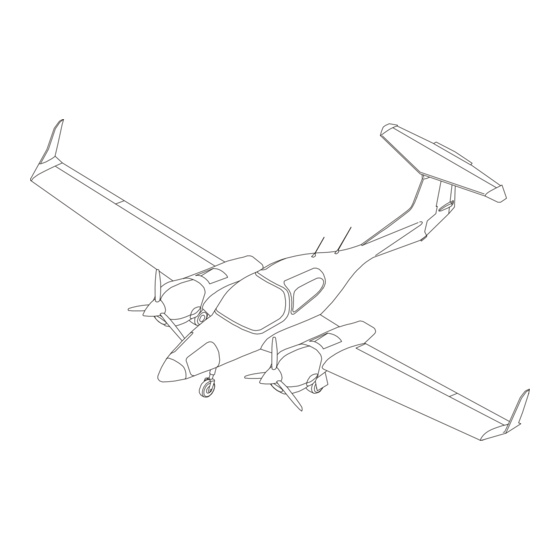
- Page 69 GENERAL DESCRIPTION OF THE AIRPLANE 1. Description The DA 42 NG is a twin-engine, four seat, low wing mono-plane. It has a cantilever wing and a ‘T’ tail. The airplane structure is fiber reinforced plastic composite. This gives a very strong but lightweight structure.
- Page 70 General Description DA 42 NG AMM AIRCRAFT The semi-monocoque fuselage is a carbon-fiber reinforced-plastic (CFRP) shell with glass-fiber reinforced-plastic (GFRP) bulkheads and stiffeners. The fuselage is constructed in 2 halves that are bonded together after installation of the fuselage bulkheads and frames. Carbon fiber is used in many areas to give increased strength and rigidity.
- Page 71 Switches and circuit breakers control all electrical devices. A key switch controls the engine starting system. The DA 42 NG has a full range of flight instruments contained in an integrated cockpit system (ICS). The ICS has 2 display screens. Both of them are able to show all the airplane flight instrumentation data, navigation data, engine data and other airplane system data.
- Page 72 The table below gives you the names and address of the manufacturers who supply systems and/or equipment for the DA 42 NG. This will help you to get more data on a system and/or equipment. "Yes" in the "Direct Shipping Approved" column means that the part can be ordered directly from the vendor.
- Page 73 DA 42 NG AMM General Description AIRCRAFT Equipment/System Manufacturer/Address Direct Chapter Shipping Approved Cooling Fans for Integrated SANDIA aerospace Cockpit System: 3700 Osuna Road NE, Suite 711 Albuquerque, NM 87109 Tel: (505) 341-2930 Fax: (505) 341-2927 Website: www.sandiaaerospace.com Battery: Concorde Battery Corp.
- Page 74 General Description DA 42 NG AMM AIRCRAFT Equipment/System Manufacturer/Address Direct Chapter Shipping Approved AmSafe Seatbelt Airbag V23 AMSAFE, Inc. System 1043 N. 47 Ave. Phoenix, AZ 85043 Tel: +1 602 850 2850 Fax: +1 602 850 2812 Website: www.amsafe.com Fire Extinguisher: Total Feuerschutz GmbH Industriestr.
- Page 75 DA 42 NG AMM General Description AIRCRAFT Equipment/System Manufacturer/Address Direct Chapter Shipping Approved Main Wheels and Brakes: Parker Hannifin Corporation Aircraft Wheel and Brake Division 1160 Center Road Avon, Cleveland, Ohio 44011 Tel: (440) 937 6211 Fax: (440) 937 6416 Website: www.parker.com...
- Page 76 General Description DA 42 NG AMM AIRCRAFT Equipment/System Manufacturer/Address Direct Chapter Shipping Approved Engine: Austro Engine GmbH Rudolf Diesel-Straße 11 A-2700 Wiener Neustadt Austria Tel: +43-2622-23000 Fax: +43-2622-23000-2711 Website: www.austroengine.at 3. Handling of Identification Data No person shall remove, change, or place identification information on any airplane, engine, propeller, propeller blade, or propeller hub, without the approval of the competent national Airworthiness Authority.
- Page 77 Airworthiness DA 42 NG AMM Limitations CHAPTER 04 AIRWORTHINESS LIMITATIONS Doc # 7.02.15 Page 1 04-TITLE Rev. 4 15 Mar 2018...
- Page 78 Airworthiness DA 42 NG AMM Limitations AIRCRAFT Intentionally left blank Page 2 Doc # 7.02.15 04-TITLE 15 Mar 2018 Rev. 4...
- Page 79 Airworthiness DA 42 NG AMM Limitations TABLE OF CONTENTS CHAPTER 04 AIRWORTHINESS LIMITATIONS Airworthiness Limitations ........3 Doc # 7.02.15...
- Page 80 Airworthiness DA 42 NG AMM Limitations AIRCRAFT Intentionally left blank Page 2 Doc # 7.02.15 04-CONTENTS 15 Mar 2018 Rev. 4...
- Page 81 Airworthiness DA 42 NG AMM Limitations CHAPTER 04 AIRWORTHINESS LIMITATIONS THIS AIRWORTHINESS LIMITATIONS SECTION IS APPROVED BY EUROPEAN AVIATION SAFETY AGENCY (EASA) IN ACCORDANCE WITH THE APPLICABLE CERTIFICATION PROCEDURES AND THE TYPE CERTIFICATION BASIS. IT SPECIFIES THE AIRWORTHINESS LIMITATIONS REQUIRED BY JAR 23.
- Page 82 Airworthiness DA 42 NG AMM Limitations AIRCRAFT Intentionally left blank Page 2 Doc # 7.02.15 04-00-00 15 Mar 2018 Rev. 4...
- Page 83 (2) Life Time Limit / Structure Checks There is no structural life limit. Note: The DA 42 NG has been designed and tested under a 'damage tolerant structure' philosophy. Therefore the structural inspections given in Chapter 05 cover all required structure checks.
- Page 84 Airworthiness DA 42 NG AMM Limitations AIRCRAFT B. Replacement Requirements The following table lists life limited airplane components which must be replaced at a specific time. Where an interval is given in both flight time and calendar years, the limit which is reached first must be applied.
- Page 85 C. Paint (1) For S/N below 42.N300/42.MN100: It is mandatory to paint the DA 42 NG white with a solar absorptivity not exceeding 0.3. This will prevent the temperature of the structure from becoming too high. Examples of approved shades are: RAL 9016.
- Page 86 (2) For S/N 42.N300/42.MN100 and above: It is mandatory to paint the DA 42 NG and DA 42 M-NG in accordance with the color paint scheme provided in Section 51-20.
- Page 87 Time Limits and DA 42 NG AMM Maintenance Checks AIRCRAFT CHAPTER 05 TIME LIMITS AND MAINTENANCE CHECKS Doc # 7.02.15 Page 1 05-TITLE Rev. 4 15 Mar 2018...
- Page 88 Time Limits and DA 42 NG AMM AIRCRAFT Maintenance Checks Intentionally left blank Page 2 Doc # 7.02.15 05-TITLE 15 Mar 2018 Rev. 4...
- Page 89 Time Limits and DA 42 NG AMM Maintenance Checks AIRCRAFT TABLE OF CONTENTS CHAPTER 05 TIME LIMITS AND MAINTENANCE CHECKS General ............1 Chapter Configuration .
- Page 90 Section 05-28-00 Maintenance Checklist DA 42 NG Engines General ............1 Preparation .
-
Page 91: Unscheduled Maintenance Checks
Time Limits and DA 42 NG AMM Maintenance Checks AIRCRAFT Section 05-28-93 Major Structural Inspection Check Findings Report General ............1... - Page 92 Time Limits and DA 42 NG AMM AIRCRAFT Maintenance Checks Intentionally left blank Page 4 Doc # 7.02.15 05-CONTENTS 15 Mar 2018 Rev. 4...
- Page 93 TIME LIMITS AND MAINTENANCE CHECKS 1. General This Chapter will help you to do the maintenance of the DA 42 NG correctly. Refer to Chapter 04-00 and 05-00 to help you when you do maintenance and inspections. The times given in this Chapter are times recommended by the airplane manufacturer. Do the scheduled maintenance at the given times, because they are the minimum required to keep the airplane in a good technical condition.
- Page 94 Section 05-25 contains the Drain Holes Inspection Checklist. E. Section 05-28 Section 05-28 contains the Maintenance Checklist for the DA 42 NG airplane. The Section is subdivided into engine and airframe Sections and provides checklists for the engines, the propellers, the airframe and the corresponding reports.
- Page 95 E509605 AmSafe Seatbelt Airbag V23 System for Diamond Aircraft, Models DA 40, DA 40 NG, DA 40 F, DA 42, DA 42 NG, and DA 42 M-NG Inflatable Restraint System Assy. Series No. 7053 and 7057. Artex Installation and Maintenance Manual for the...
- Page 96 Time Limits and DA 42 NG AMM AIRCRAFT Maintenance Checks 3. Definitions In this Airplane Maintenance Manual, the words that follow have special meanings: Adjust. To put to a specified position or condition. For example, adjust the clearance to 1 mm.
- Page 97 Time Limits and DA 42 NG AMM Maintenance Checks AIRCRAFT Record. (1) Technical name for something that shows what was done. For example, write the result of the test in the engine record. (2) The act of making a record. For example, record the result of the test in the Airplane Maintenance Log.
- Page 98 Time Limits and DA 42 NG AMM AIRCRAFT Maintenance Checks Intentionally left blank Page 6 Doc # 7.02.15 05-00-00 15 Mar 2018 Rev. 4...
- Page 99 Time Limits and DA 42 NG AMM Maintenance Checks AIRCRAFT Section 05-10 Time Limits 1. General All scheduled maintenance checks have time limits. You must do the scheduled maintenance within the time limits. The flight time recorded in the airplane log book is the time that is relevant for the time limits.
- Page 100 Time Limits and DA 42 NG AMM AIRCRAFT Maintenance Checks Scheduled Maintenance Check Interval Flight Hours Calendar Time 100 Hour Check. 100 ± 10 200 Hour Check. 200 ± 10 12 months ± 30 days 1000 Hour Check. 1000 ± 50 2000 Hour Check.
- Page 101 Time Limits and DA 42 NG AMM Maintenance Checks AIRCRAFT 4. Component Time Limits Note: Those component time limits which are Airworthiness Limitations are also listed in Chapter 04. A. Maintenance Requirements The following table lists airplane components and systems which require overhaul or specific checks.
- Page 102 Time Limits and DA 42 NG AMM AIRCRAFT Maintenance Checks Interval Maintenance Component Requirement hrs. calendar time 4 yrs ± 60 days Airspeed indicators Ensure correct indication. (G1000 and backup). 2 yrs ± 30 days* 4 yrs ± 60 days Vertical speed indicator Ensure correct indication.
- Page 103 Time Limits and DA 42 NG AMM Maintenance Checks AIRCRAFT B. Airplane Life-Limited Components The following table lists life limited airplane components which must be replaced at a specific time. Where an interval is given in both flight time and calendar time, the limit which is reached first must be applied.
- Page 104 Time Limits and DA 42 NG AMM AIRCRAFT Maintenance Checks Component Replacement Time hrs. calendar time Fuel filter elements. 100 ± 10 1 yr ± 30 days Co-incident If MÄM 42-471 is carried out: with engine Fuel pressure pulsation damper.
- Page 105 Time Limits and DA 42 NG AMM Maintenance Checks AIRCRAFT Component Replacement Time hrs. calendar time Co-incident Coolant silicate pouch. with engine 6 yrs. ± 60 days TBO. 5. Component Time Tracking To make sure that components overhaul/replacement is done at the correct time you must record the data that follows in the Airplane Maintenance Log for each component requiring overhaul/replacement: - Serial Number.
- Page 106 Time Limits and DA 42 NG AMM AIRCRAFT Maintenance Checks Intentionally left blank Page 8 Doc # 7.02.15 05-10-00 15 Mar 2018 Rev. 4...
- Page 107 Time Limits and DA 42 NG AMM Maintenance Checks AIRCRAFT Section 05-20 Scheduled Maintenance Checks 1. General Do the scheduled maintenance checks in this Section at the intervals (flight hours and calendar time) stated in Section 05-10, Paragraph 3. Note: Only persons or maintenance organizations authorized by national Regulatory Authorities of the country where the airplane is registered may do these checks.
- Page 108 Time Limits and DA 42 NG AMM AIRCRAFT Maintenance Checks All of the applicable items must be signed by authorized maintenance personnel. Record the completion of the check in the airplane log book. Complete a copy of the Maintenance Report (refer to Section 05-28-90).
- Page 109 The Major Structural Inspection (MSI) is an important part of the infinite lifetime concept of the DA 42 NG. It is required to prove the structural integrity of the airframe. It must be carried out at the intervals shown in Section 05-10.
- Page 110 Time Limits and DA 42 NG AMM AIRCRAFT Maintenance Checks Intentionally left blank Page 4 Doc # 7.02.15 05-20-00 15 Mar 2018 Rev. 4...
- Page 111 ACCIDENTS CAN OCCUR IF THE PRE-FLIGHT CHECK IS NOT DONE CORRECTLY. The schedule for the pilot's pre-flight check is furnished in the Airplane Flight Manual for the DA 42 NG. 3. Post-Flight Check Do the post-flight check after the last flight of the day. The post-flight check includes all the steps of the pre-flight check.
- Page 112 Time Limits and DA 42 NG AMM AIRCRAFT Maintenance Checks Intentionally left blank Page 2 Doc # 7.02.15 05-21-00 15 Mar 2018 Rev. 4...
- Page 113 Time Limits and DA 42 NG AMM Maintenance Checks AIRCRAFT Section 05-25 Drain Holes Inspection Checklist and Report 1. General Do a check of the drain holes. The drain holes must not be blocked by dirt or other residues. Make sure to remove all foreign objects and clean the drain holes to their full diameter.
- Page 114 Time Limits and DA 42 NG AMM AIRCRAFT Maintenance Checks 2. Drain Holes Inspection Checklist Drain Holes Inspection Checklist Ref. Drain Hole Location Hours Initials FUSELAGE 1.01 Lower shell, in front of radar frame (if neither OÄM 42-119 nor OÄM 42-273 is installed).
- Page 115 Time Limits and DA 42 NG AMM Maintenance Checks AIRCRAFT Drain Holes Inspection Checklist Ref. Drain Hole Location Hours Initials 1.18 Flange top at main landing gear in front of rear box - spar (LH and RH). 1.19 Lower center wing shell aft rear spar center position.
- Page 116 Time Limits and DA 42 NG AMM AIRCRAFT Maintenance Checks Drain Holes Inspection Checklist Ref. Drain Hole Location Hours Initials 1.38 Through roll over bar duct and baggage compartment frame. 1.39 In rear of nose baggage compartment RH. 2000 CANOPY AND DOOR 2.01...
- Page 117 Time Limits and DA 42 NG AMM Maintenance Checks AIRCRAFT Drain Holes Inspection Checklist Ref. Drain Hole Location Hours Initials ELEVATOR TRIM TAB 5.01 Lower shell, leading edge section (LH and RH). 5.02 Lower shell, in front of trailing edge bonding (LH and RH).
- Page 118 Time Limits and DA 42 NG AMM AIRCRAFT Maintenance Checks Drain Holes Inspection Checklist Ref. Drain Hole Location Hours Initials FLAPS 8.01 Root rib, next to trailing edge bonding (LH and RH). 8.02 Inner flap root rib, next to trailing edge bonding (LH and RH).
- Page 119 Time Limits and DA 42 NG AMM Maintenance Checks AIRCRAFT 1.25 1.25 1.27 1.05 1.01 1.25 1.02 1.03 1.04 Drainage Holes 11mm View from below 1.39 1.05 1.03 1.26 1.25 1.04 1.26 1.03 1.05 1.27 Drainage Holes 11mm 100 Hours Check...
- Page 120 Time Limits and DA 42 NG AMM AIRCRAFT Maintenance Checks 1.33 To be checked only 1.09 in production or repair 1.32 1.38 1.31 1.31 1.30 1.29 1.28 1.07 To be checked only 1.35 in production or repair 1.06 1.08 100 Hours Check...
- Page 121 Time Limits and DA 42 NG AMM Maintenance Checks AIRCRAFT 2.02 2.01 2.01 2.02 100 Hours Check Horizontal Drainage Hole 200 Hours Check Vertical Drainage Hole 2000 Hours Check Exterior Drainage Hole Drainage Hole Inside the Structure Figure 3: Drain Holes Canopy Doc # 7.02.15...
- Page 122 Time Limits and DA 42 NG AMM AIRCRAFT Maintenance Checks 2.03 100 Hours Check Horizontal Drainage Hole 200 Hours Check Vertical Drainage Hole 2000 Hours Check Exterior Drainage Hole Drainage Hole Inside the Structure Figure 4: Drain Holes Door Page 10 Doc # 7.02.15...
- Page 123 Time Limits and DA 42 NG AMM Maintenance Checks AIRCRAFT 3.07 3.07 3.02 3.06 3.06 3.09 3.09 3.05 3.01 3.05 3.08 3.08 3.04 3.04 4.01 4.01 4.02 4.02 3.03 3.07 5.01 5.01 5.02 5.02 100 Hours Check Horizontal Drainage Hole...
- Page 124 Time Limits and DA 42 NG AMM AIRCRAFT Maintenance Checks 6.02 6.01 100 Hours Check Horizontal Drainage Hole 200 Hours Check Vertical Drainage Hole 2000 Hours Check Exterior Drainage Hole Drainage Hole Inside the Structure Figure 6: Drain Holes Rudder Page 12 Doc # 7.02.15...
- Page 125 Time Limits and DA 42 NG AMM Maintenance Checks AIRCRAFT 6.02 6.01 100 Hours Check Horizontal Drainage Hole 200 Hours Check Vertical Drainage Hole 2000 Hours Check Exterior Drainage Hole Drainage Hole Inside the Structure Figure 7: Drain Holes Rudder (if MÄM 42-600 is installed) Doc # 7.02.15...
- Page 126 Time Limits and DA 42 NG AMM AIRCRAFT Maintenance Checks VIEW FROM UNDER In Cowling Base In Cowling Base 1.10 1.10 1.13 1.11 1.11 To be checked only in To be checked only in Production or Repair Production or Repair 1.15...
- Page 127 Time Limits and DA 42 NG AMM Maintenance Checks AIRCRAFT Maintenance Access Maintenance Access 7.11 7.09 7.08 7.07 7.12 7.10 7.03 7.01 9.02 7.12 7.09 7.08 7.07 9.04 7.06 7.04 7.05 9.03 7.02 9.01 8.01 View A 7.06 7.09 100 Hours Check...
- Page 128 Time Limits and DA 42 NG AMM AIRCRAFT Maintenance Checks Intentionally left blank Page 16 Doc # 7.02.15 05-25-00 15 Mar 2018 Rev. 4...
- Page 129 Time Limits and DA 42 NG AMM Maintenance Checks AIRCRAFT Section 05-28 Maintenance Checklist DA 42 NG Section 05-28-00 Maintenance Checklist DA 42 NG Engines 1. General Enter the applicable data in the blocks below: Registration _________________ Date _________________ Airplane S/N...
- Page 130 Time Limits and DA 42 NG AMM AIRCRAFT Maintenance Checks 3. Engine Ground Test Do an engine ground test as follows (complete a copy of the Engine Ground Test Record as part of the engine ground test. (Refer to Section 05-28-91)):...
- Page 131 Time Limits and DA 42 NG AMM Maintenance Checks AIRCRAFT 4. Maintenance Checklist Engines A. LH Engine 100 hr items marked * apply to US registered airplanes only Interval Inspection Items, LH Engine 100 200 1000 2000 Time Initials WARNING: MAKE SURE THE EXHAUST SYSTEM IS COOL BEFORE YOU DO MAINTENANCE ON THE ENGINE.
- Page 132 Time Limits and DA 42 NG AMM AIRCRAFT Maintenance Checks 100 hr items marked * apply to US registered airplanes only Interval Inspection Items, LH Engine 100 200 1000 2000 Time Initials Examine the fuel inline filter element in the rear nacelle (if auxiliary tanks are installed): S If filters are damaged replace them.
- Page 133 Time Limits and DA 42 NG AMM Maintenance Checks AIRCRAFT 100 hr items marked * apply to US registered airplanes only Interval Inspection Items, LH Engine 100 200 1000 2000 Time Initials Examine the air intake hoses: S Look specially for signs of damage.
- Page 134 Time Limits and DA 42 NG AMM AIRCRAFT Maintenance Checks 100 hr items marked * apply to US registered airplanes only Interval Inspection Items, LH Engine 100 200 1000 2000 Time Initials Examine the propeller control system: Refer also to mt-Propeller Operation and Installation manual, latest revision.
- Page 135 Time Limits and DA 42 NG AMM Maintenance Checks AIRCRAFT 100 hr items marked * apply to US registered airplanes only Interval Inspection Items, LH Engine 100 200 1000 2000 Time Initials Examine the air intake and turbo-charging system. Look specially at these items: S Air filter.
- Page 136 Time Limits and DA 42 NG AMM AIRCRAFT Maintenance Checks 100 hr items marked * apply to US registered airplanes only Interval Inspection Items, LH Engine 100 200 1000 2000 Time Initials Inspect the v-clamp on the pressure side of the turbo...
- Page 137 Time Limits and DA 42 NG AMM Maintenance Checks AIRCRAFT 100 hr items marked * apply to US registered airplanes only Interval Inspection Items, LH Engine 100 200 1000 2000 Time Initials Check cooling system for leaks. Look specially at these items: S Hoses and hose clamps.
- Page 138 Time Limits and DA 42 NG AMM AIRCRAFT Maintenance Checks 100 hr items marked * apply to US registered airplanes only Interval Inspection Items, LH Engine 100 200 1000 2000 Time Initials Examine the engine mounts. Look specially for: S Cracks or corrosion. No cracks or corrosion allowed.
- Page 139 Time Limits and DA 42 NG AMM Maintenance Checks AIRCRAFT B. RH Engine 100 hr items marked * apply to US registered airplanes only Interval Inspection Items, RH Engine 100 200 1000 2000 Time Initials WARNING: MAKE SURE THE EXHAUST SYSTEM IS COOL BEFORE YOU DO MAINTENANCE ON THE ENGINE.
- Page 140 Time Limits and DA 42 NG AMM AIRCRAFT Maintenance Checks 100 hr items marked * apply to US registered airplanes only Interval Inspection Items, RH Engine 100 200 1000 2000 Time Initials Examine the fuel inline filter element in the rear nacelle (if auxiliary tanks are installed): S If filters are damaged replace them.
- Page 141 Time Limits and DA 42 NG AMM Maintenance Checks AIRCRAFT 100 hr items marked * apply to US registered airplanes only Interval Inspection Items, RH Engine 100 200 1000 2000 Time Initials Examine the oil breather line. Refer to the AE Maintenance Manual, latest revision.
- Page 142 Time Limits and DA 42 NG AMM AIRCRAFT Maintenance Checks 100 hr items marked * apply to US registered airplanes only Interval Inspection Items, RH Engine 100 200 1000 2000 Time Initials Examine the air intake and turbo-charging system. Look specially at these items: S Air filter.
- Page 143 Time Limits and DA 42 NG AMM Maintenance Checks AIRCRAFT 100 hr items marked * apply to US registered airplanes only Interval Inspection Items, RH Engine 100 200 1000 2000 Time Initials Inspect the v-clamp on the pressure side of the turbo...
- Page 144 Time Limits and DA 42 NG AMM AIRCRAFT Maintenance Checks 100 hr items marked * apply to US registered airplanes only Interval Inspection Items, RH Engine 100 200 1000 2000 Time Initials Check cooling system for leaks. Look specially at these items: S Hoses and hose clamps.
- Page 145 Time Limits and DA 42 NG AMM Maintenance Checks AIRCRAFT 100 hr items marked * apply to US registered airplanes only Interval Inspection Items, RH Engine 100 200 1000 2000 Time Initials Examine the engine mounts. Look specially for: S Cracks or corrosion. No cracks or corrosion allowed.
- Page 146 Time Limits and DA 42 NG AMM AIRCRAFT Maintenance Checks 5. Propellers A. LH Propeller 100 hr items marked * apply to US registered airplanes only Interval Inspection Items, LH Propeller 100 200 1000 2000Time Initials WARNING: DO NOT LET PERSONS GO INTO THE DANGER AREA OF THE PROPELLER.
- Page 147 Time Limits and DA 42 NG AMM Maintenance Checks AIRCRAFT Section 05-28-50 Maintenance Checklist Airframe 1. Exterior of the Fuselage A. General 100 hr items marked * apply to US registered airplanes only Interval Inspection Items, Exterior Fuselage, General 100 200 1000 2000Time Initials Examine the complete surface of the fuselage.
- Page 148 Time Limits and DA 42 NG AMM AIRCRAFT Maintenance Checks B. Nose Landing Gear 100 hr items marked * apply to US registered airplanes only Interval Inspection Items, Nose Landing Gear 100 200 1000 2000Time Initials Examine the composite structure to which the nose landing gear assembly is attached.
- Page 149 Time Limits and DA 42 NG AMM Maintenance Checks AIRCRAFT 100 hr items marked * apply to US registered airplanes only Interval Inspection Items, Nose Landing Gear 100 200 1000 2000Time Initials Disassemble and examine the nose landing gear leg: S Remove the nose landing gear leg.
- Page 150 Time Limits and DA 42 NG AMM AIRCRAFT Maintenance Checks C. Main Landing Gear 100 hr items marked * apply to US registered airplanes only Interval Inspection Items, Main Landing Gear 100 200 1000 2000Time Initials Examine the composite structure to which the main landing gear assembly is attached.
- Page 151 Time Limits and DA 42 NG AMM Maintenance Checks AIRCRAFT 100 hr items marked * apply to US registered airplanes only Interval Inspection Items, Main Landing Gear 100 200 1000 2000Time Initials If MÄM 42-659 is NOT installed, examine the interior of the dampers: S Disassemble the dampers.
- Page 152 Time Limits and DA 42 NG AMM AIRCRAFT Maintenance Checks D. Wheels 100 hr items marked * apply to US registered airplanes only Interval Inspection Items, Wheels 100 200 1000 2000Time Initials Examine the tires: S Look for cuts and wear.
- Page 153 Time Limits and DA 42 NG AMM Maintenance Checks AIRCRAFT E. Fuselage Nose 100 hr items marked * apply to US registered airplanes only Interval Inspection Items, Fuselage Nose 100 200 1000 2000Time Initials Examine the nose baggage doors: S Check for damage to the doors.
- Page 154 Time Limits and DA 42 NG AMM AIRCRAFT Maintenance Checks 100 hr items marked * apply to US registered airplanes only Interval Inspection Items, Fuselage Nose 100 200 1000 2000Time Initials Visually inspect the interior structure of the front fuselage (forward of instrument panel frame). Use mirror and flashlight where necessary.
- Page 155 Time Limits and DA 42 NG AMM Maintenance Checks AIRCRAFT 100 hr items marked * apply to US registered airplanes only Interval Inspection Items, Fuselage Nose 100 200 1000 2000Time Initials If the GWX 68 or GWX 70 weather radar system (OÄM 42-119 or OÄM 42-273) is installed:...
- Page 156 Time Limits and DA 42 NG AMM AIRCRAFT Maintenance Checks 2. Cabin A. Cabin, General 100 hr items marked * apply to US registered airplanes only Interval Inspection Items, Cabin, General 100 200 1000 2000 Time Initials Remove the inspection hole covers. Remove front and rear seat shells.
- Page 157 Time Limits and DA 42 NG AMM Maintenance Checks AIRCRAFT B. Canopy, Doors, and Windows 100 hr items marked * apply to US registered airplanes only Interval Inspection Items, Canopy, Doors, and Windows 100 200 1000 2000Time Initials Examine the canopy: S Make sure the canopy lock mechanism operates correctly.
- Page 158 Time Limits and DA 42 NG AMM AIRCRAFT Maintenance Checks 100 hr items marked * apply to US registered airplanes only Interval Inspection Items, Canopy, Doors, and Windows 100 200 1000 2000Time Initials Examine the carbon hinges for cracks. (Refer to Section 52-10).
- Page 159 Time Limits and DA 42 NG AMM Maintenance Checks AIRCRAFT C. Cabin Structure 100 hr items marked * apply to US registered airplanes only Interval Inspection Items, Cabin Structure 100 200 1000 2000Time Initials Visually inspect the inner skin of the front fuselage (forward of baggage compartment frame).
- Page 160 Time Limits and DA 42 NG AMM AIRCRAFT Maintenance Checks 100 hr items marked * apply to US registered airplanes only Interval Inspection Items, Cabin Structure 100 200 1000 2000Time Initials Visually inspect the bolts that attach the center wing to the fuselage.
- Page 161 Time Limits and DA 42 NG AMM Maintenance Checks AIRCRAFT 100 hr items marked * apply to US registered airplanes only Interval Inspection Items, Instrument Panel and 100 200 1000 2000Time Initials Electrical System in Cabin Examine the attachments of the instrument panel.
- Page 162 Time Limits and DA 42 NG AMM AIRCRAFT Maintenance Checks 100 hr items marked * apply to US registered airplanes only Interval Inspection Items, Instrument Panel and 100 200 1000 2000Time Initials Electrical System in Cabin Examine the compass. Make sure that: S The compass is correctly attached.
- Page 163 Time Limits and DA 42 NG AMM Maintenance Checks AIRCRAFT 100 hr items marked * apply to US registered airplanes only Interval Inspection Items, Flight Control System in Cabin 100 200 1000 2000Time Initials Examine the aileron and elevator control system. Look specially for: S Incorrect attachment.
- Page 164 Time Limits and DA 42 NG AMM AIRCRAFT Maintenance Checks 100 hr items marked * apply to US registered airplanes only Interval Inspection Items, Flight Control System in Cabin 100 200 1000 2000Time Initials Examine the rudder cables and pulleys. Look specially for: S Incorrect attachment and function.
- Page 165 Time Limits and DA 42 NG AMM Maintenance Checks AIRCRAFT 100 hr items marked * apply to US registered airplanes only Interval Inspection Items, Flight Control System in Cabin 100 200 1000 2000Time Initials Examine the rear part of the steering linkage. Look specially for: S Damage and corrosion.
- Page 166 Time Limits and DA 42 NG AMM AIRCRAFT Maintenance Checks 100 hr items marked * apply to US registered airplanes only Interval Inspection Items, Flight Control System in Cabin 100 200 1000 2000Time Initials Check the following components of the autopilot system for wear and/or corrosion: S Servos.
- Page 167 Time Limits and DA 42 NG AMM Maintenance Checks AIRCRAFT 100 hr items marked * apply to US registered airplanes only Interval Inspection Items, Other Cockpit Controls 100 200 1000 2000Time Initials Examine the fuel selector valve controls (FUEL CONTROL): S Check levers for damage.
- Page 168 Time Limits and DA 42 NG AMM AIRCRAFT Maintenance Checks 100 hr items marked * apply to US registered airplanes only Interval Inspection Items, Other Cockpit Controls 100 200 1000 2000Time Initials Examine the control cables in the center console: S Examine visually the cables in the center console.
- Page 169 Time Limits and DA 42 NG AMM Maintenance Checks AIRCRAFT 100 hr items marked * apply to US registered airplanes only Interval Inspection Items, Cabin, Miscellaneous 100 200 1000 2000Time Initials If the oxygen system is installed (OÄM 42-055), visually inspect the oxygen pressure gauge in the cabin.
- Page 170 Time Limits and DA 42 NG AMM AIRCRAFT Maintenance Checks 3. Interior of the Rear Fuselage A. Interior Structure of the Rear Fuselage 100 hr items marked * apply to US registered airplanes only Interval Inspection Items, Interior Structure of the Rear...
- Page 171 Time Limits and DA 42 NG AMM Maintenance Checks AIRCRAFT 100 hr items marked * apply to US registered airplanes only Interval Inspection Items, Interior Structure of the Rear 100 200 1000 2000Time Initials Fuselage Examine the RACC air inlets and outlets (if OÄM 42-193/c or earlier is carried out):...
- Page 172 Time Limits and DA 42 NG AMM AIRCRAFT Maintenance Checks 100 hr items marked * apply to US registered airplanes only Interval Inspection Items, Interior Structure of the Rear 100 200 1000 2000Time Initials Fuselage Examine the RACC central unit (if OÄM 42-193 is carried out).
- Page 173 Time Limits and DA 42 NG AMM Maintenance Checks AIRCRAFT B. Hydraulic System in the Rear Fuselage 100 hr items marked * apply to US registered airplanes only Interval Inspection Items, 100 200 1000 2000Time Initials Hydraulic System in the Rear Fuselage Check hydraulic module platform for improper or insecure attachment.
- Page 174 Time Limits and DA 42 NG AMM AIRCRAFT Maintenance Checks D. Miscellaneous Items in the Rear Fuselage 100 hr items marked * apply to US registered airplanes only Interval Inspection Items, 100 200 1000 2000Time Initials Miscellaneous Items in the Rear Fuselage Do an inspection of the ELT system.
- Page 175 Time Limits and DA 42 NG AMM Maintenance Checks AIRCRAFT 100 hr items marked * apply to US registered airplanes only Interval Inspection Items, 100 200 1000 2000Time Initials Miscellaneous Items in the Rear Fuselage Examine the RACC central unit (if OÄM 42-193 is carried out).
- Page 176 Time Limits and DA 42 NG AMM AIRCRAFT Maintenance Checks 4. Center Wing A. Center Wing, Exterior 100 hr items marked * apply to US registered airplanes only Interval Inspection Items, Center Wing, Exterior 100 200 1000 2000Time Initials Remove all access panels in the center wing and the engine nacelles.
- Page 177 Time Limits and DA 42 NG AMM Maintenance Checks AIRCRAFT 100 hr items marked * apply to US registered airplanes only Interval Inspection Items, Center Wing, Exterior 100 200 1000 2000Time Initials Remove the wings from the center wing. (Refer to Section 57-10): S Examine the main bolts.
- Page 178 Time Limits and DA 42 NG AMM AIRCRAFT Maintenance Checks B. Center Wing, Interior 100 hr items marked * apply to US registered airplanes only Interval Inspection Items, Center Wing, Interior 100 200 1000 2000Time Initials Visually inspect the inner skin of the center wing through all access holes with mirror and flashlight.
- Page 179 Time Limits and DA 42 NG AMM Maintenance Checks AIRCRAFT 100 hr items marked * apply to US registered airplanes only Interval Inspection Items, Center Wing, Interior 100 200 1000 2000Time Initials Examine the outer surfaces of the front and rear main spars, specially in the area of the bushes for the main bolts.
- Page 180 Time Limits and DA 42 NG AMM AIRCRAFT Maintenance Checks D. Miscellaneous Items in Center Wing & Nacelles 100 hr items marked * apply to US registered airplanes only Interval Inspection Items, Center Wing, Miscellaneous 100 200 1000 2000Time Initials...
- Page 181 Time Limits and DA 42 NG AMM Maintenance Checks AIRCRAFT B. Structure of the Vertical Tail 100 hr items marked * apply to US registered airplanes only Interval Inspection Items, Structure of the Vertical Tail 100 200 1000 2000Time Initials Examine the complete surface of the vertical stabilizer.
- Page 182 Time Limits and DA 42 NG AMM AIRCRAFT Maintenance Checks C. Structure of the Horizontal Stabilizer 100 hr items marked * apply to US registered airplanes only Interval Inspection Items, 100 200 1000 2000 Time Initials Structure of the Horizontal Stabilizer Examine the complete surface of the horizontal stabilizer.
- Page 183 Time Limits and DA 42 NG AMM Maintenance Checks AIRCRAFT 100 hr items marked * apply to US registered airplanes only Interval Inspection Items, 100 200 1000 2000 Time Initials Structure of the Horizontal Stabilizer Visually inspect the interior structure of the horizontal stabilizer through all access holes with mirror and flashlight.
- Page 184 Time Limits and DA 42 NG AMM AIRCRAFT Maintenance Checks D. Rudder 100 hr items marked * apply to US registered airplanes only Interval Inspection Items, Rudder 100 200 1000 2000Time Initials Examine the rudder skin. Look specially for: S Dents, cracks, holes, dis-bonding, and delamination.
- Page 185 Time Limits and DA 42 NG AMM Maintenance Checks AIRCRAFT E. Rudder Hinges and Control System in Vertical Tail 100 hr items marked * apply to US registered airplanes only Interval Inspection Items, Rudder Hinges and Control 100 200 1000 2000Time Initials System in Vertical Tail Examine the rudder control cables.
- Page 186 Time Limits and DA 42 NG AMM AIRCRAFT Maintenance Checks 100 hr items marked * apply to US registered airplanes only Interval Inspection Items, Rudder Hinges and Control 100 200 1000 2000Time Initials System in Vertical Tail Check the friction of the rudder trim mechanism. Verify smooth running on trim knob and proper function.
- Page 187 Time Limits and DA 42 NG AMM Maintenance Checks AIRCRAFT F. Elevator and Elevator Hinges 100 hr items marked * apply to US registered airplanes only Interval Inspection Items, Elevator and Elevator Hinges 100 200 1000 2000Time Initials Examine the elevator skin. Look specially for: S Dents, cracks, holes, dis-bonding, and delamination.
- Page 188 Time Limits and DA 42 NG AMM AIRCRAFT Maintenance Checks G. Elevator Control System in Tail 100 hr items marked * apply to US registered airplanes only Interval Inspection Items, Elevator Control System in Tail 100 200 1000 2000Time Initials...
- Page 189 Time Limits and DA 42 NG AMM Maintenance Checks AIRCRAFT 100 hr items marked * apply to US registered airplanes only Interval Inspection Items, Elevator Control System in Tail 100 200 1000 2000Time Initials Adjust the friction of the elevator trim mechanism.
- Page 190 Time Limits and DA 42 NG AMM AIRCRAFT Maintenance Checks 6. Wings A. Wings, General 100 hr items marked * apply to US registered airplanes only Interval Inspection Items, Wings, General 100 200 1000 2000Time Initials Remove the winglets. (Refer to Section 57-10).
- Page 191 Time Limits and DA 42 NG AMM Maintenance Checks AIRCRAFT B. Wings, Structure 100 hr items marked * apply to US registered airplanes only Interval Inspection Items, Wings, Structure 100 200 1000 2000Time Initials Examine the complete surface of the wings. Look specially for damage (dents, cracks, holes and delamination).
- Page 192 Time Limits and DA 42 NG AMM AIRCRAFT Maintenance Checks 100 hr items marked * apply to US registered airplanes only Interval Inspection Items, Wings, Structure 100 200 1000 2000Time Initials Visually inspect the interior structure of the LH and RH wing through all access holes with mirror and flashlight or endoscope.
- Page 193 Time Limits and DA 42 NG AMM Maintenance Checks AIRCRAFT C. Ailerons and Outer Flaps 100 hr items marked * apply to US registered airplanes only Interval Inspection Items, Ailerons and Outer Flaps 100 200 1000 2000Time Initials Examine the ailerons. Look specially for damage (dents, cracks, holes and delamination).
- Page 194 Time Limits and DA 42 NG AMM AIRCRAFT Maintenance Checks 100 hr items marked * apply to US registered airplanes only Interval Inspection Items, Ailerons and Outer Flaps 100 200 1000 2000Time Initials Examine the aileron and flap control system. Look specially for incorrect attachment and loose or missing lock devices.
- Page 195 Time Limits and DA 42 NG AMM Maintenance Checks AIRCRAFT D. Fuel Tanks 100 hr items marked * apply to US registered airplanes only Interval Inspection Items, Fuel Tanks 100 200 1000 2000Time Initials Note: The inspection items shown in this table must also be applied to the auxiliary fuel tanks.
- Page 196 Time Limits and DA 42 NG AMM AIRCRAFT Maintenance Checks 100 hr items marked * apply to US registered airplanes only Interval Inspection Items, Fuel Tanks 100 200 1000 2000Time Initials Install the access covers. Examine the fuel tank vents for blockage.
- Page 197 Time Limits and DA 42 NG AMM Maintenance Checks AIRCRAFT E. Wings, Miscellaneous 100 hr items marked * apply to US registered airplanes only Interval Inspection Items, Wings, Miscellaneous 100 200 1000 2000 Time Initials Examine the Pitot-static probe. Look specially for: S Incorrect attachment.
- Page 198 Time Limits and DA 42 NG AMM AIRCRAFT Maintenance Checks 7. General 100 hr items marked * apply to US registered airplanes only Interval Inspection Items, General 100 200 1000 2000 Time Initials Examine the Pitot-static system. S Clean the Pitot-static system. (Refer to Section 34-10).
- Page 199 Time Limits and DA 42 NG AMM Maintenance Checks AIRCRAFT 100 hr items marked * apply to US registered airplanes only Interval Inspection Items, General 100 200 1000 2000 Time Initials Do an operational test of the variable elevator stop.
- Page 200 Time Limits and DA 42 NG AMM AIRCRAFT Maintenance Checks 100 hr items marked * apply to US registered airplanes only Interval Inspection Items, General 100 200 1000 2000 Time Initials Do a test of the steering linkage and nose wheel centering device: S Move the nose wheel to the left and right.
- Page 201 Time Limits and DA 42 NG AMM Maintenance Checks AIRCRAFT 100 hr items marked * apply to US registered airplanes only Interval Inspection Items, General 100 200 1000 2000 Time Initials Examine the airplane. Look specially for foreign objects, for example loose items and tools. Install these items, if previously removed: S All access panels.
- Page 202 Time Limits and DA 42 NG AMM AIRCRAFT Maintenance Checks 100 hr items marked * apply to US registered airplanes only Interval Inspection Items, General 100 200 1000 2000 Time Initials Complete the Maintenance Report and put it in the Airplane Maintenance Log.
- Page 203 Time Limits and DA 42 NG AMM Maintenance Checks AIRCRAFT Section 05-28-90 Maintenance Report 1. Maintenance Report Complete a copy of the Maintenance Report after all of the applicable maintenance tasks in the Maintenance Checklist have been initialed. DA 42 NG...
- Page 204 Time Limits and DA 42 NG AMM AIRCRAFT Maintenance Checks Intentionally left blank Page 2 Doc # 7.02.15 05-28-90 15 Mar 2018 Rev. 4...
- Page 205 Time Limits and DA 42 NG AMM Maintenance Checks AIRCRAFT Section 05-28-91 Engine Ground Test Record 1. Engine Ground Test Record Do the engine test in accordance with Section 71-00 and record results and comments. WARNING: DO NOT STAND WITHIN THE DANGER AREA OF THE PROPELLER.
- Page 206 Time Limits and DA 42 NG AMM AIRCRAFT Maintenance Checks Intentionally left blank Page 2 Doc # 7.02.15 05-28-91 15 Mar 2018 Rev. 4...
- Page 207 Time Limits and DA 42 NG AMM Maintenance Checks AIRCRAFT Section 05-28-92 Check Flight Report 1. Check Flight Report Note: The maintenance check flight must be done in accordance with the applicable national regulations. MAINTENANCE CHECK FLIGHT DA 42 NG...
- Page 208 Time Limits and DA 42 NG AMM AIRCRAFT Maintenance Checks CHECK FLIGHT DA 42 NG (See Maintenance Checklist for Applicability) AIRCRAFT Page 2 of 6 Findings Functional Check, Flight Behavior Oxygen system (if installed). ON GROUND, ENGINES ON Engine start in accordance with AFM.
- Page 209 Time Limits and DA 42 NG AMM Maintenance Checks AIRCRAFT CHECK FLIGHT DA 42 NG (See Maintenance Checklist for Applicability) AIRCRAFT Page 3 of 6 Findings Functional Check, Flight Behavior Autopilot (disconnect). Audio panel / intercom. COM 1 / COM 2.
- Page 210 Time Limits and DA 42 NG AMM AIRCRAFT Maintenance Checks CHECK FLIGHT DA 42 NG (See Maintenance Checklist for Applicability) AIRCRAFT Page 4 of 6 Findings Functional Check, Flight Behavior CLIMB (in accordance with AFM) Trim (pitch, direction). CRUISE (in accordance with AFM) Control behavior.
- Page 211 Time Limits and DA 42 NG AMM Maintenance Checks AIRCRAFT CHECK FLIGHT DA 42 NG (See Maintenance Checklist for Applicability) AIRCRAFT Page 5 of 6 Findings Functional Check, Flight Behavior ADF (if required). Transponder. Moving map / GPS position. Autopilot: S Wings level mode.
- Page 212 Time Limits and DA 42 NG AMM AIRCRAFT Maintenance Checks CHECK FLIGHT DA 42 NG (See Maintenance Checklist for Applicability) AIRCRAFT Page 6 of 6 Findings Functional Check, Flight Behavior DESCENT AND LANDING (in accordance with AFM) Function of flaps.
- Page 213 Complete the Structural Findings Report after each Major Structural Inspection (MSI). Record the following: Structural defects found during the MSI. All structural defects that were detected and repaired since new or since the last MSI. STRUCTURAL FINDINGS REPORT DA 42 NG AT MAJOR STRUCTURAL INSPECTION (MSI) Registration __________________...
- Page 214 Time Limits and DA 42 NG AMM AIRCRAFT Maintenance Checks structural defect/finding repair method, remarks at TSN All defects have been repaired. The airplane is airworthy with respect to its maintenance condition. Place: _____________________________________ Date: _____________________________________ Authorized: _____________________________________ Page 2 Doc # 7.02.15...
- Page 215 Time Limits and DA 42 NG AMM Maintenance Checks AIRCRAFT Section 05-50 Unscheduled Maintenance Checks 1. General Unscheduled maintenance checks are necessary after any incident that could cause damage to the airplane. 2. Hard Landing Check Figure 1 shows the hard landing check areas. You must do a hard landing check when the pilot makes a report of a hard landing.
- Page 216 Time Limits and DA 42 NG AMM AIRCRAFT Maintenance Checks Detail Steps/Work Items Key Items Examine the tires. Look specially for cuts in the Refer to Section 32-40. side walls. Examine the brake discs. Look specially for damage. Turn the wheel and make sure the disc is not bent.
- Page 217 Time Limits and DA 42 NG AMM Maintenance Checks AIRCRAFT Detail Steps/Work Items Key Items If the adjustable front seats (OÄM 42-067 or OÄM-42-259) are installed: CAUTION: DO NOT LOOSEN THE LEVER FOR THE ADJUSTABLE BACKREST OF THE FRONT SEATS UNINTENTIONALLY. THE SPRING LOADED BACKREST MAY SNAP FORWARD AND CAN CAUSE INJURY.
- Page 218 Time Limits and DA 42 NG AMM AIRCRAFT Maintenance Checks Front Main Bulkhead Folding Stay Pivot Plate Folding Stay Rib Rear Main Bulkhead Main Landing Gear Rib Front Closing Rib Rear Mounting Front Mounting Main Landing Gear Leg LH Shown,...
- Page 219 Time Limits and DA 42 NG AMM Maintenance Checks AIRCRAFT Bearings for Nose Gear Assembly Bulkhead Folding Stay Mounting Nose Gear Assembly Figure 2: Hard Landing Check Areas - Nose Landing Gear Doc # 7.02.15 Page 5 05-50-00 15 Mar 2018...
- Page 220 Time Limits and DA 42 NG AMM AIRCRAFT Maintenance Checks 3. Gear Up Landing Check Detail Steps/Work Items Key Items Perform a hard landing check. Refer to Paragraph 2, Hard Landing Check. Examine the nose cone in the propeller area for external damages.
- Page 221 Time Limits and DA 42 NG AMM Maintenance Checks AIRCRAFT 4. Propeller Strike A propeller strike can be a moving propeller (engine running) which has hit a solid object. Or it can be a moving object that hits a propeller that is not moving.
- Page 222 Time Limits and DA 42 NG AMM AIRCRAFT Maintenance Checks 5. Engine Fire WARNING: BEFORE YOU DO WORK ON THE AIRPLANE MAKE SURE THE FIRE HAS BEEN EXTINGUISHED. LET THE ENGINE COOL AND DISCONNECT THE BATTERY. WARNING: FIRE CAN SERIOUSLY WEAKEN CFRP. IF YOU FIND ANY DAMAGE TO CFRP, DO NOT OPERATE THE AIRPLANE.
- Page 223 Time Limits and DA 42 NG AMM Maintenance Checks AIRCRAFT Detail Steps/Work Items Key Items Examine the engine nacelles. Look specially for: S Blisters on the paint or burn marks. S Disbonding of the nacelle skin from the firewall. If you find any damage, ask the airplane manufacturer for advice.
- Page 224 Refer to the Wiring Diagrams for data about the electrical wiring. Note: If you find any lightning damage you must make a record of the damage and ask Diamond Aircraft for advice before you repair or operate the airplane. Page 10 Doc # 7.02.15 05-50-00 15 Mar 2018 Rev.
- Page 225 S Propellers and spinners. Make a record of the damage you find S Exhaust pipes. and ask Diamond Aircraft for advice before you repair or operate the S Engine breather. airplane. S Canopy handles.
- Page 226 S Pitot-static probe. Make a record of the damage you find S Stall warning switch. and ask Diamond Aircraft for advice before you repair or operate the S Static discharge wicks. airplane. S Winglet.
- Page 227 Make a record of the damage you find S Horizontal stabilizer tip. and ask Diamond Aircraft for advice S Static discharge wicks. before you repair or operate the airplane. S Trailing edge.
- Page 228 Time Limits and DA 42 NG AMM AIRCRAFT Maintenance Checks Detail Steps/Work Items Key Items Do a test of these lighting systems: S External lights: Refer to Section 33-40. S Position lights. S Strobe lights. S Landing light. S Taxi light.
- Page 229 Time Limits and DA 42 NG AMM Maintenance Checks AIRCRAFT Detail Steps/Work Items Key Items (15) Operate the cockpit heating controls through Refer to Section 21-40. their range of movement. Look specially for: S Stiff or unusual feel during movement.
- Page 230 Time Limits and DA 42 NG AMM AIRCRAFT Maintenance Checks 7. Over Temperature Detail Steps/Work Items Key Items Check the fluid level and leakage. Check data and oil sample and send it to Austro Engine GmbH. 8. High Oil Consumption...
- Page 231 Time Limits and DA 42 NG AMM Maintenance Checks AIRCRAFT 11. Overweight Landing Check You must do an overweight landing check when the pilot makes a report of a landing with a mass in excess of the maximum landing mass (overweight landing). In case the pilot reports a hard and overweight landing, refer to Paragraph 2, Hard Landing Check.
- Page 232 Time Limits and DA 42 NG AMM AIRCRAFT Maintenance Checks Intentionally left blank Page 18 Doc # 7.02.15 05-50-00 15 Mar 2018 Rev. 4...
- Page 233 DA 42 NG AMM Dimensions and Areas AIRCRAFT CHAPTER 06 DIMENSIONS AND AREAS Doc # 7.02.15 Page 1 06-TITLE Rev. 4 15 Mar 2018...
- Page 234 Dimensions and Areas DA 42 NG AMM AIRCRAFT Intentionally left blank Page 2 06-TITLE Doc # 7.02.15 15 Mar 2018 Rev. 4...
- Page 235 DA 42 NG AMM Dimensions and Areas AIRCRAFT TABLE OF CONTENTS CHAPTER 06 DIMENSIONS AND AREAS General ............1 Dimensions .
- Page 236 Dimensions and Areas DA 42 NG AMM AIRCRAFT Intentionally left blank Page 2 Doc # 7.02.15 06-CONTENTS 15 Mar 2018 Rev. 4...
- Page 237 DIMENSIONS AND AREAS 1. General The DA 42 NG uses the System Internationale (SI) for dimensions and areas. Imperial dimensions are also given in brackets. For example: Wing span 13.42 m (44.03 ft). Conversions between SI units and imperial units are given in Chapter 02.
- Page 238 2.95 m (9 ft 8 in.) 13.42 m (44 ft 0 in.) 13.55 m (44 ft 5 in.) 1.735 m (5 ft 8 in.) Figure 1: DA 42 NG Overall Dimensions (Approximate Values) Page 2 Doc # 7.02.15 06-00-00 15 Mar 2018...
- Page 239 DA 42 NG AMM Dimensions and Areas AIRCRAFT 2. Dimensions DA 42 NG Dimensions Overall Dimensions Wing span 13.42 m (44 ft) 13.55 m (44 ft 5 in) including ACL Length 8.56 m (28 ft 1 in) Height (nominal) 2.49 m (8 ft 2 in)
- Page 240 Dimensions and Areas DA 42 NG AMM AIRCRAFT DA 42 NG Dimensions Aileron Span 2 x 1.67 m (2 x 5 ft 6 in) Area 2 x 0.33 m² (2 x 3.55 ft²) Outer Flaps Span 2 x 2.83 m (2 x 9 ft 3 in) Area 2 x 0.65 m²...
- Page 241 AIRCRAFT 3. Adjustment Reports The measurements of the DA 42 NG are recorded on an Adjustment Report and the Main Landing Gear Wheel Track and Camber Report at the factory when the airplane is built. See Figures 2 thru 10.
- Page 242 Dimensions and Areas DA 42 NG AMM AIRCRAFT (1) Control Surface Adjustment Reports Flaps Ailerons Take-Off Neutral right right right right right right left left left left left left 0 +8/-0 81 +16/-8 (see A) 167 +12/-4 (see B) 87 ±7 (see E) 0 ±3.5...
- Page 243 DA 42 NG AMM Dimensions and Areas AIRCRAFT Elevator Rudder down left right up with variable elevator stop active Top View Figure 3: Control Surfaces Adjustment Report - Elevator and Rudder Doc # 7.02.15 Page 7 06-00-00 Rev. 4 15 Mar 2018...
- Page 244 Dimensions and Areas DA 42 NG AMM AIRCRAFT Elevator Trim Elevator 10° Up Elevator Neutral Elevator 10° Down Figure 4: Control Surfaces Adjustment Report - Elevator Trim Page 8 Doc # 7.02.15 06-00-00 15 Mar 2018 Rev. 4...
- Page 245 DA 42 NG AMM Dimensions and Areas AIRCRAFT Rudder Trim Rudder 20° LH Rudder neutral Rudder 20° RH Travel Limits [mm] 15 ±4 61 ±6 25 ±6 51 4 ± 47 ±6 3 ±4 7 ±2 47 ±4 58 ±6 Travel Limits [in.]...
- Page 246 Dimensions and Areas DA 42 NG AMM AIRCRAFT Rudder Trim 40 ±5* 16 ±3* 26 ±5* 48 ±3 10 ±3 36 ±5 3 ±3* Trim LH Neutral Trim RH Rudder Trim LH Neutral Trim RH Rudder Trim LH Neutral Trim RH * Needs only be checked, if rudder trim system components are replaced.
- Page 247 DA 42 NG AMM Dimensions and Areas AIRCRAFT Rudder Trim 40 ±6 1 ±4 42 ±6 50 ±4 4 ±2 45 ±4 54 ±6 8 ±4 31 ±5 35 ±5 1 ±3 36 ±5 43 ±3 3 ±2 39 ±5 47 ±5...
- Page 248 Dimensions and Areas DA 42 NG AMM AIRCRAFT Figure 8: Adjustment Report, General Items (Metric Dimensions) Page 12 Doc # 7.02.15 06-00-00 15 Mar 2018 Rev. 4...
- Page 249 DA 42 NG AMM Dimensions and Areas AIRCRAFT Figure 9: Adjustment Report, General Items (Imperial Dimensions) Doc # 7.02.15 Page 13 06-00-00 Rev. 4 15 Mar 2018...
- Page 250 Dimensions and Areas DA 42 NG AMM AIRCRAFT Main Landing Gear Wheel Track and Camber Report (for test/adjustment procedure refer to Section 32-10 Paragraph 11) Check procedure Measured data Perform check at basic weight (fuel tank empty). Set airplane MLG wheels on relocatable plates (2 steel plates 250 x 300 x 2 mm;...
- Page 251 DA 42 NG AMM Dimensions and Areas AIRCRAFT δ = 0° ± 1° 0 ± 0.5° ° 0 ± 0.5° ° Direction of Flight δ < 0° δ > 0° δ > 0° δ < 0° MLG loaded with basic weight.
- Page 252 Dimensions and Areas DA 42 NG AMM AIRCRAFT Intentionally left blank Page 16 Doc # 7.02.15 06-00-00 15 Mar 2018 Rev. 4...
- Page 253 Lifting and Shoring DA 42 NG AMM General AIRCRAFT CHAPTER 07 LIFTING AND SHORING - GENERAL Doc # 7.02.15 Page 1 07-TITLE Rev. 4 15 Mar 2018...
- Page 254 Lifting and Shoring DA 42 NG AMM General AIRCRAFT Intentionally left blank Page 2 Doc # 7.02.15 07-TITLE 15 Mar 2018 Rev. 4...
- Page 255 Lifting and Shoring DA 42 NG AMM General AIRCRAFT TABLE OF CONTENTS CHAPTER 07 LIFTING AND SHORING - GENERAL General ............1...
- Page 256 Lifting and Shoring DA 42 NG AMM General AIRCRAFT Intentionally left blank Page 2 Doc # 7.02.15 07-CONTENTS 15 Mar 2018 Rev. 4...
- Page 257 LIFTING AND SHORING - GENERAL 1. General The DA 42 NG has no lifting points. You must use straps to lift the airplane. Two persons can lift the outer wing, or the horizontal stabilizer, or any of the airplane control surfaces.
- Page 258 Lifting and Shoring DA 42 NG AMM General AIRCRAFT Intentionally left blank Page 2 Doc # 7.02.15 07-00-00 15 Mar 2018 Rev. 4...
- Page 259 Jacking 1. General The DA 42 NG has three jacking points. There are two main jacking points under each stub-wing and the tie-down hole in the lower fin makes the tail jacking point. For maintenance lift the fuselage with three hydraulic jacks. Use a trestle with a special former to hold the front of the fuselage. Use standard trestles under the wings at the position where the winglets connect to the wing.
- Page 260 Lifting and Shoring DA 42 NG AMM General AIRCRAFT Wing Trestle Wing Trestle Main Jack Nose Trestle Main Jack Tail Jacking Point Nose Trestle Main Jacking Point Ballast Tail Jack LH & RH Figure 1: Lifting the Airplane on Jacks Page 2 Doc # 7.02.15...
- Page 261 Lifting and Shoring DA 42 NG AMM General AIRCRAFT B. Lifting the Airplane Detail Steps/Work Items Key Items/References CAUTION: IF THE AIRPLANE IS IN THE OPEN THEN ALIGN IT INTO THE WIND. MAXIMUM WIND SPEED: 10 KM/H (6 KTS). Put chocks under the main wheels.
- Page 262 Lifting and Shoring DA 42 NG AMM General AIRCRAFT C. Lowering the Airplane Detail Steps/Work Items Key Items/References WARNING: MAKE SURE THAT THE AREA UNDER THE AIRPLANE IS CLEAR BEFORE YOU LOWER THE AIRPLANE WITH THE JACKS. Remove the nose trestle from under the front fuselage.
- Page 263 Lifting and Shoring DA 42 NG AMM General AIRCRAFT Section 07-11 Hoisting 1. General You do not need any lifting equipment to remove the wings and you do not need any lifting equipment to remove the horizontal stabilizer. Use a sling assembly similar to the sling assembly shown in Figure 1. The sling assembly must have a lifting capacity of 2000 kg (4410 lb).
- Page 264 Lifting and Shoring DA 42 NG AMM General AIRCRAFT Sling Assembly Shackle Lifting Beam Rear Strap Front Strap Centre of Gravity Figure 1: Hoisting the Airplane Page 2 Doc # 7.02.15 07-11-00 15 Mar 2018 Rev. 4...
- Page 265 DA 42 NG AMM Leveling and Weighing AIRCRAFT CHAPTER 08 LEVELING AND WEIGHING Doc # 7.02.15 Page 1 08-TITLE Rev. 4 15 Mar 2018...
- Page 266 Leveling and Weighing DA 42 NG AMM AIRCRAFT Intentionally left blank Page 2 Doc # 7.02.15 08-TITLE 15 Mar 2018 Rev. 4...
- Page 267 DA 42 NG AMM Leveling and Weighing AIRCRAFT TABLE OF CONTENTS CHAPTER 08 LEVELING AND WEIGHING General ............1...
- Page 268 Leveling and Weighing DA 42 NG AMM AIRCRAFT Intentionally left blank Page 2 Doc # 7.02.15 08-CONTENTS 15 Mar 2018 Rev. 4...
- Page 269 DA 42 NG AMM Leveling and Weighing AIRCRAFT CHAPTER 08 LEVELING AND WEIGHING 1. General This Chapter tells you how to weigh the airplane. It also tells you how to level the airplane. Use the procedures given in Section 08-10 to weigh the airplane and to calculate the airplane moment. Use the procedures in Section 08-20 to level the airplane.
- Page 270 Leveling and Weighing DA 42 NG AMM AIRCRAFT Intentionally left blank Page 2 Doc # 7.02.15 08-00-00 15 Mar 2018 Rev. 4...
- Page 271 The reference plane for the DA 42 NG is a transverse, vertical plane in front of the airplane. It is at right angles to the horizontal reference line. The reference plane lies at 2196 mm (86.46 in) in front of the stub-wing leading edge at the wing root rib.
- Page 272 Leveling and Weighing DA 42 NG AMM AIRCRAFT Spirit Level Horizontal Part of Baggage Compartment Frame Figure 1: Level the Airplane Laterally for Weighing Page 2 Doc # 7.02.15 08-10-00 15 Mar 2018 Rev. 4...
- Page 273 DA 42 NG AMM Leveling and Weighing AIRCRAFT Reference Plane Arm - Empty Weight X 2196 mm (86.46 in.) Main Ramps (Height of Main Scale+ Height of Block) Ramp same Height as Nose Scale Blocks to Level the Airplane = 2780 mm (109.45 in.) = 925 mm (36.42 in.)
- Page 274 Leveling and Weighing DA 42 NG AMM AIRCRAFT 2. Weighing with Mechanical Scales Under the Wheels If you use mechanical scales to weigh the airplane, you must also use wooden blocks under the wheels to level the airplane. You must obey the manufacturers instructions for using the scales.
- Page 275 DA 42 NG AMM Leveling and Weighing AIRCRAFT B. Weighing Procedure with Mechanical Scales Under the Wheels Detail Steps/Work Items Key Items/References Note: Weigh the airplane in a closed room. This will avoid any wind caused weighing errors. Make a copy of the Weighing Report form.
- Page 276 Leveling and Weighing DA 42 NG AMM AIRCRAFT Detail Steps/Work Items Key Items/References (11) Make the airplane level longitudinally: Refer to Figure 2. S Place a spirit level on the top surface of the front baggage compartment floor, left side.
- Page 277 DA 42 NG AMM Leveling and Weighing AIRCRAFT Detail Steps/Work Items Key Items/References (19) Use the plumb line to mark the position of the nose wheel center line on the floor. (20) Use the plumb line to mark the position of each main wheel center line on the floor.
- Page 278 AIRCRAFT WEIGHING REPORT Model: DA 42 NG Serial Number:___________ Registration:_____________ Data with reference to the Type Certificate Data Sheet and the Airplane Flight Manual. Reference Plane: Vertical plane 2196 mm (86.46 in) in front of the leading edge of wing at the root rib.
- Page 279 DA 42 NG AMM Leveling and Weighing AIRCRAFT Section 08-20 Leveling 1. General These procedures tell you how to make the airplane level. See Section 07-10 for lifting the airplane with jacks. Make the airplane level with jacks unless you are weighing the airplane.
- Page 280 Leveling and Weighing DA 42 NG AMM AIRCRAFT Spirit Level Horizontal Part of Baggage Compartment Frame Figure 1: Level the Airplane Laterally Spirit Level on the top surface of the front baggage compartment floor, left side. Figure 2: Level the Airplane Longitudinally Page 2 Doc # 7.02.15...
- Page 281 DA 42 NG AMM Leveling and Weighing AIRCRAFT B. Level the Airplane with Jacks Detail Steps/Work Items Key Items/References Note: Level the airplane in a closed room. Fasten the ballast with the belt at the airplane. Refer to Figure 2.
- Page 282 Leveling and Weighing DA 42 NG AMM AIRCRAFT Intentionally left blank Page 4 Doc # 7.02.15 08-20-00 15 Mar 2018 Rev. 4...
- Page 283 Towing and Taxiing DA 42 NG AMM General AIRCRAFT CHAPTER 09 TOWING AND TAXIING - GENERAL Doc # 7.02.15 Page 1 09-TITLE Rev. 4 15 Mar 2018...
- Page 284 Towing and Taxiing DA 42 NG AMM General AIRCRAFT Intentionally left blank Page 2 Doc # 7.02.15 09-TITLE 15 Mar 2018 Rev. 4...
- Page 285 Towing and Taxiing DA 42 NG AMM General AIRCRAFT TABLE OF CONTENTS CHAPTER 09 TOWING AND TAXIING - GENERAL General ............1...
- Page 286 Towing and Taxiing DA 42 NG AMM General AIRCRAFT Intentionally left blank Page 2 Doc # 7.02.15 09-CONTENTS 15 Mar 2018 Rev. 4...
- Page 287 Towing and Taxiing DA 42 NG AMM General AIRCRAFT CHAPTER 09 TOWING AND TAXIING - GENERAL 1. General You can move the airplane on the ground by hand or by taxiing. Use the procedures in Section 09-10 and Section 09-20 to move the airplane safely. Section 09-10 tells you how to tow the airplane. Section 09-20 tells you how to taxi the airplane.
- Page 288 Towing and Taxiing DA 42 NG AMM General AIRCRAFT Intentionally left blank Page 2 Doc # 7.02.15 09-00-00 15 Mar 2018 Rev. 4...
- Page 289 DA 42 NG at the inner section of the propeller blades near the spinners. You can push the DA 42 NG at the wing nose and at the rough upper surface of the center wing, inboard of the engine nacelle.
- Page 290 Towing and Taxiing DA 42 NG AMM General AIRCRAFT A. Movement by Hand To move the airplane on ground, it can be pushed or pulled by hand on the inner section of the propeller blades near the spinner or pushed at the wing nose and at the rough surface of the center wing, inboard of the nacelles.
- Page 291 Towing and Taxiing DA 42 NG AMM General AIRCRAFT B. Movement with a Tow Vehicle When towing the airplane with a tow vehicle, a qualified person must sit in the cockpit ready for immediate braking action, in the event that the tow vehicle becomes uncoupled. The movement of the tow vehicle should always be started and stopped slowly to avoid shock loads on the nose landing gear.
- Page 292 Towing and Taxiing DA 42 NG AMM General AIRCRAFT Intentionally left blank Page 4 Doc # 7.02.15 09-10-00 15 Mar 2018 Rev. 4...
- Page 293 Section 09-20 Taxiing 1. General The DA 42 NG can easily be taxied by using the nose wheel steering. To reduce the turn radius the wheel brakes furthered by asymmetric power can be used. WARNING: DO NOT TAXI THE AIRPLANE UNLESS YOU HAVE BEEN TRAINED TO TAXI AND YOU HAVE BEEN AUTHORIZED.
- Page 294 Towing and Taxiing DA 42 NG AMM General AIRCRAFT Figure 1: The Safety Area for Taxiing the DA 42 NG Airplane Page 2 Doc # 7.02.15 09-20-00 15 Mar 2018 Rev. 4...
- Page 295 POSSIBLE RPM TO REDUCE THE RISK OF FOREIGN OBJECT DAMAGE TO THE PROPELLERS. Taxi the airplane to the new position. Shut down the engines. Refer to the DA 42 NG Airplane Flight Manual. Park the airplane. If necessary, moor the Refer to Chapter 10-00.
- Page 296 Towing and Taxiing DA 42 NG AMM General AIRCRAFT Intentionally left blank Page 4 Doc # 7.02.15 09-20-00 15 Mar 2018 Rev. 4...
- Page 297 Parking, Mooring and DA 42 NG AMM Storage AIRCRAFT CHAPTER 10 PARKING, MOORING, STORAGE AND RETURN TO SERVICE Doc # 7.02.15 Page 1 10-TITLE Rev. 4 15 Mar 2018...
- Page 298 Parking, Mooring and DA 42 NG AMM Storage AIRCRAFT Intentionally left blank Page 2 Doc # 7.02.15 10-TITLE 15 Mar 2018 Rev. 4...
- Page 299 Parking, Mooring and DA 42 NG AMM Storage AIRCRAFT TABLE OF CONTENTS CHAPTER 10 PARKING, MOORING, STORAGE AND RETURN TO SERVICE General ............1...
- Page 300 Parking, Mooring and DA 42 NG AMM Storage AIRCRAFT Intentionally left blank Page 2 Doc # 7.02.15 10-CONTENTS 15 Mar 2018 Rev. 4...
- Page 301 1. General Always park or moor the DA 42 NG when it is not in use. Use the procedures given in Section 10-10 for parking the airplane. Use the procedures given in Section 10-20 to moor the airplane. If the airplane is parked overnight we recommend that you moor the airplane.
- Page 302 Parking, Mooring and DA 42 NG AMM Storage AIRCRAFT Intentionally left blank Page 2 Doc # 7.02.15 10-00-00 15 Mar 2018 Rev. 4...
- Page 303 5 to 30 days. Use the storage procedure when the airplane will be parked for more than 30 days. All pilots and all maintenance staff for the DA 42 NG must know the procedures in this Section. CAUTION: MAKE SURE THAT THE AIRPLANE IS CORRECTLY MOORED AND PROTECTED IF STRONG WINDS ARE FORECAST.
- Page 304 Parking, Mooring and DA 42 NG AMM Storage AIRCRAFT Detail Steps/Work Items Key Items/References CAUTION: DO NOT APPLY THE PARKING BRAKE WHEN THE BRAKES ARE OVER-HEATED. THE BRAKES CAN SEIZE ON. Set the parking brake ON. Pull the lever fully aft, and push both the brake pedals at least two times.
- Page 305 Parking, Mooring and DA 42 NG AMM Storage AIRCRAFT C. Long-Term Parking CAUTION: MAKE SURE THAT YOU DO THE LONG TERM PARKING PROCEDURE WHEN YOU PARK THE AIRPLANE FOR A LONG TIME. IF YOU DO NOT DO THE LONG TERM PARKING PROCEDURE CORRECTLY, THE ENGINE CYLINDERS AND WHEEL BEARINGS CAN CORRODE.
- Page 306 Parking, Mooring and DA 42 NG AMM Storage AIRCRAFT Detail Steps/Work Items Key Items/References Install the gust lock: S Move the rudder pedals fully rearward. S Engage the control surfaces gust lock with the pedals. S Engage the stick; wrap straps around stick once.
- Page 307 Parking, Mooring and DA 42 NG AMM Storage AIRCRAFT 2. Storage If the airplane is parked (or not operated) for more than 30 days, you have to do this storage procedure. A. Equipment and Material Item Quantity Part Number Wheel chocks.
- Page 308 Parking, Mooring and DA 42 NG AMM Storage AIRCRAFT C. Monthly Routine Check Do these steps each month while the airplane is stored. Detail Steps/Work Items Key Items/References Remove all plugs from the engine openings. Tighten the v-ribbed belt. Refer to AE Maintenance Manual, latest revision.
- Page 309 Parking, Mooring and DA 42 NG AMM Storage AIRCRAFT Section 10-20 Mooring 1. General CAUTION: IF THE AIRPLANE MUST BE STORED OUTSIDE FOR A LONG TIME, IT HAS TO BE MOORED. STRONG WINDS OR GUSTS CAN CAUSE DAMAGE TO AN AIRPLANE WHICH IS NOT MOORED.
- Page 310 Parking, Mooring and DA 42 NG AMM Storage AIRCRAFT Wing Tie-Down Point Wing Tie-Down Point Mooring Ring Rear Tie-Down Point Figure 1: Location of Mooring Points on the Airplane Page 2 Doc # 7.02.15 10-20-00 15 Mar 2018 Rev. 4...
- Page 311 Parking, Mooring and DA 42 NG AMM Storage AIRCRAFT Section 10-30 Return to Service 1. General Do this procedure when the airplane has been parked (or stored) for more than 5 days. 2. Return to Service Procedure A. Storage Time Less Than One Year...
- Page 312 Parking, Mooring and DA 42 NG AMM Storage AIRCRAFT Detail Steps/Work Items Key Items/References (13) Remove the gust lock: S Loosen the straps and detach the locks. S Disengage the stick from the straps. S Disengage the pedals from the gust lock.
- Page 313 DA 42 NG AMM Placards and Markings AIRCRAFT CHAPTER 11 PLACARDS AND MARKINGS Doc # 7.02.15 Page 1 11-TITLE Rev. 4 15 Mar 2018...
- Page 314 Placards and Markings DA 42 NG AMM AIRCRAFT Intentionally left blank Page 2 11-TITLE Doc # 7.02.15 15 Mar 2018 Rev. 4...
- Page 315 DA 42 NG AMM Placards and Markings AIRCRAFT TABLE OF CONTENTS CHAPTER 11 PLACARDS AND MARKINGS General ............1 Replace Plastic Foil Placards .
- Page 316 Placards and Markings DA 42 NG AMM AIRCRAFT Intentionally left blank Page 2 Doc # 7.02.15 11-CONTENTS 15 Mar 2018 Rev. 4...
- Page 317 DA 42 NG AMM Placards and Markings AIRCRAFT CHAPTER 11 PLACARDS AND MARKINGS 1. General Placards are used for identification and indication. They show the function, operation and operating limitations of systems and equipment. Note: Placards must not be removed, exchanged or altered unless approved by the national Airworthiness Authority.
- Page 318 Placards and Markings DA 42 NG AMM AIRCRAFT B. Replace a Placard Use this procedure for both internal and external foil placards. Detail Steps/Work Items Key Items/References Remove the old placard: Do not over-heat the composite structure. S Warm the placard with a hot air blower.
-
Page 319: Exterior Placards And Markings
Exterior Placards and Markings 1. General Figure 1 shows the exterior placards for the DA 42 NG airplane. If OÄM 42-187 is installed the safety walk is a coated safety walk instead of safety walk with adhesive strips. Refer to Section 51-20 for coated safety walk repair procedures. - Page 320 Placards and Markings DA 42 NG AMM AIRCRAFT LH and RH LH and RH Diamond AIRCRAFT LH and RH LH and RH LH and RH LH and RH LH and RH Figure 2: Design Example for Exterior Markings Page 2 Doc # 7.02.15...
- Page 321 DA 42 NG AMM Placards and Markings AIRCRAFT Maintenance Practices 1. General This Section tells you how to replace safety walk adhesive strips. 2. Replace the Safety Walk Adhesive Strips A. Equipment Item Quantity Part Number Safety walk template. D64-1127-10-52.
- Page 322 Placards and Markings DA 42 NG AMM AIRCRAFT Detail Steps/Work Items Key Items/References Remove the adhesives layer of the safety walk adhesive strips from surface: S Use fresh acetone or Socomore® cleaning cloth (P/N: 29003-C86-C10) to remove the adhesive layer. Do not use cleaning or polishing agents which contain silicon.
- Page 323 DA 42 NG AMM Placards and Markings AIRCRAFT Place nose of Place nose of Safety Walk Template Safety Walk Template on fuselage wall on fuselage wall No Step Place triangular marker to trailing edge Foot Step Figure 3: Safety Walk Template Positioning Doc # 7.02.15...
- Page 324 Placards and Markings DA 42 NG AMM AIRCRAFT Intentionally left blank Page 204 Doc # 7.02.15 11-20-00 15 Mar 2018 Rev. 4...
- Page 325 2. Description The DA 42 NG has self adhesive foil placards for the cockpit interior. The instrument panel has placard panels which are attached to the instrument panel with screws. The placard panels have integral lighting which is controlled by a combined ON/OFF dimmer switch. The dimmer switch is mounted on the top left of the instrument panel.
- Page 326 Placards and Markings DA 42 NG AMM AIRCRAFT (Inside door behind handle) (If OÄM 42-207 is installed) COCKPIT BAGGAGE BAGGAGE STANDARD BAGGAGE SHORT BAGG AGE COMPARTMENT EXTENSION COMPARTMENT EXTENSION MAX. 45 kg [100 lb] MAX. 18 kg [40 lb] MAX 30 kg [66 lb] MAX 15 kg [33 lb] ARM: 3 89 m [153 1"]...
- Page 327 DA 42 NG AMM Placards and Markings AIRCRAFT N 30 60 E Steer Optional Steer EMERGENCY DATE RADIOS ON, PITOT OFF GPS NOT APPROVED FOR WAAS OPERATIONS Optional DO NOT OPERATE SYSTEM Fo r N 3 0 6 0 E...
- Page 328 Placards and Markings DA 42 NG AMM AIRCRAFT NO SMOKING LH MAIN BUS COM1 GPS/NAV1 XPDR ENG INST D E I C E XFER PUMP PITOT DE-ICE TAXI/MAP FLOOD GEAR WRN AHRS ELEV LIMIT GEAR RH MAIN BUS LH ENGINE...
- Page 329 DA 42 NG AMM Placards and Markings AIRCRAFT If OÄM 42-270 is installed Figure 4: Placard Panels - Sheet 2 Doc # 7.02.15 Page 5 11-30-00 Rev. 4 15 Mar 2018...
- Page 330 Placards and Markings DA 42 NG AMM AIRCRAFT The placards shown in Figures 5 thru 8 are installed only if the optional oxygen system is installed (OÄM 42-055 is incorporated): Figure 5: Placard on the Refill Unit, on the LH Side of the Nose Baggage Compartment...
- Page 331 DA 42 NG AMM Placards and Markings AIRCRAFT If OÄM 42-193 is carried out the following placard is mounted next to the compressor: NOTE Contains fluorinated greenhouse gas covered by the Kyoto Protocol. 1,1,1,2 - Tetrafluoroethane Figure 9: RACC Compressor Placard...
- Page 332 Placards and Markings DA 42 NG AMM AIRCRAFT Intentionally left blank Page 8 Doc # 7.02.15 11-30-00 15 Mar 2018 Rev. 4...
- Page 333 DA 42 NG AMM Placards and Markings AIRCRAFT Maintenance Practices 1. General This Section tells you how to replace a placard panel. You cannot repair a placard panel. 2. Replace a Placard Panel Use this procedure for all of the placard panels.
- Page 334 Placards and Markings DA 42 NG AMM AIRCRAFT Detail Steps/Work Items Key Items/References Do a test for the correct operation of the placard panel lights: S Set the ELECT. MASTER to ON. S Rotate the INSTRUMENT dimmer switch The placard lights must come on.
- Page 335 DA 42 NG AMM Servicing - General AIRCRAFT CHAPTER 12 SERVICING - GENERAL Doc # 7.02.15 Page 1 12-TITLE Rev. 4 05 May 2016...
- Page 336 Servicing - General DA 42 NG AMM AIRCRAFT Intentionally left blank Page 2 12-TITLE Doc # 7.02.15 15 Mar 2018 Rev. 4...
- Page 337 DA 42 NG AMM Servicing - General AIRCRAFT TABLE OF CONTENTS CHAPTER 12 SERVICING General ............1...
- Page 338 Servicing - General DA 42 NG AMM AIRCRAFT Intentionally left blank Page 2 12-CONTENTS Doc # 7.02.15 15 Mar 2018 Rev. 4...
- Page 339 DA 42 NG AMM Servicing - General AIRCRAFT CHAPTER 12 SERVICING 1. General This Chapter gives the servicing tasks which apply to the whole airplane: Section 12-10. Replenishment procedures for various systems. Section 12-20. Lubrication data. Section 12-30. Cleaning and snow and ice removal.
- Page 340 Servicing - General DA 42 NG AMM AIRCRAFT Intentionally left blank Page 2 12-00-00 Doc # 7.02.15 15 Mar 2018 Rev. 4...
- Page 341 A. Main Fuel Tanks There are three interconnected fuel tanks in each wing holding the fuel for the DA 42 NG. The fuel capacity is 26 US gal (98.4 liter) per wing. The tanks are located in the wing outboard of the engine nacelles, between the main spars.
- Page 342 Servicing - General DA 42 NG AMM AIRCRAFT WARNING: MAKE SURE THAT A SUITABLE FIRE EXTINGUISHER IS AVAILABLE AT ALL TIMES DURING REFUELING/DEFUELING. WARNING: TURN OFF ALL GROUND EQUIPMENT IN THE REFUELING AREA. WARNING: DO NOT OPERATE ELECTRICAL SWITCHES IN THE AIRPLANE DURING REFUELING.
- Page 343 DA 42 NG AMM Servicing - General AIRCRAFT Fuel Hydraulic Fluid Fuel Brake Fluid (on Co-Pilot's Brake Pedals) Fuel Fuel Nitrogen & Oil Tire Air (LH & RH) Tire Air Nitrogen & Oil (LH & RH) Coolant Gear Oil Engine Oil Figure 1: Replenishment Points Doc # 7.02.15...
- Page 344 Servicing - General DA 42 NG AMM AIRCRAFT 3. Refueling/Defueling A. Refueling Detail Steps/Work Items Key Items/References Shut down the engines. ENGINE MASTER OFF. All occupants leave the airplane. Ground the airplane electrically. At the refueling connection. Ground the refueling vehicle electrically.
- Page 345 DA 42 NG AMM Servicing - General AIRCRAFT B. Defueling Detail Items/Work Steps Key Items/References Ground the airplane electrically. At the refueling connection. Put a suitable container below the drain valve Make sure that you have enough for the wing that you will defuel.
- Page 346 Servicing - General DA 42 NG AMM AIRCRAFT 4. Fuel Contamination Test A. Equipment Item Quantity Part Number Glass container. Commercial. B. Fuel Contamination Test Procedure Detail Steps/Work Items Key Items/References Put the glass container under the fuel tank drain valve that you will take the fuel from.
- Page 347 CAUSE ENGINE MALFUNCTION OR DAMAGE. The engines installed in the DA 42 NG have a wet sump oil system. The engine oil sump can hold 7 liter (7.4 US qt). You must only use engine oil specified by the engine manufacturer.
- Page 348 Servicing - General DA 42 NG AMM AIRCRAFT Figure 2 : Engine Oil Filler/Dip-Stick Page 8 12-10-00 Doc # 7.02.15 15 Mar 2018 Rev. 4...
- Page 349 DA 42 NG AMM Servicing - General AIRCRAFT 6. Gearbox Oil WARNING: ENGINE OPERATION WITH NO GEARBOX OIL (OR VERY LOW OIL LEVEL) WILL CAUSE ENGINE MALFUNCTION OR FAILURE. Refer to the AE Maintenance Manual, latest revision for proper gearbox oil level.
- Page 350 Servicing - General DA 42 NG AMM AIRCRAFT To Thermostat Filler Cap Expansion Tank Coolant Bypass Hose Pressure Regulating Valve Figure 3: Engine Coolant Expansion Tank / Filler Cap Page 10 12-10-00 Doc # 7.02.15 15 Mar 2018 Rev. 4...
- Page 351 DA 42 NG AMM Servicing - General AIRCRAFT To Thermostat Filler Cap Silicate Pouch Cartridge Max. Coolant Level Marking Plate Expansion Tank Coolant Bypass Hose Pressure Relief Valve Coolant Level Sensor Figure 4: Engine Coolant Expansion Tank / Filler Cap (if MÄM 42-852 is installed) Doc # 7.02.15...
- Page 352 ENGINE WITH A FAULTY COOLING SYSTEM CAN DAMAGE THE ENGINE The DA 42 NG engines use liquid coolant to cool the engine and supply heating to the flight cabin. The coolant is circulated around the engine in an integral water jacket. When the coolant is at normal engine operating temperature a thermostatic valve directs the coolant to flow through a heat exchanger.
- Page 353 DA 42 NG AMM Servicing - General AIRCRAFT A. Replenish the Engine Coolant Detail Steps / Work Items Key Items / References Remove the top engine cowling. WARNING: DO NOT REMOVE THE EXPANSION TANK FILLER CAP WHEN THE ENGINE IS HOT. THE TANK IS PRESSURIZED WITH HOT COOLANT.
- Page 354 Servicing - General DA 42 NG AMM AIRCRAFT Detail Steps / Work Items Key Items / References Do an engine ground run until the engine Refer to Section 71-00. reaches normal operating temperature. Then shut-down the engine. Repeat steps 1 thru 6 until the coolant level remains constant at the correct level.
- Page 355 DA 42 NG AMM Servicing - General AIRCRAFT 8. Brake System The brake fluid reservoirs are located on the brake master cylinders on the co-pilot's side. You get access in the cockpit below the instrument panel. WARNING: DO NOT GET BRAKE FLUID ON YOUR SKIN OR IN YOUR MOUTH.
- Page 356 Servicing - General DA 42 NG AMM AIRCRAFT 9. Ice Protection System The ice protection system is optional equipment (OÄM 40-053 carried out). The deicing fluid tank is installed in the nose compartment of the airplane, on the RH side. It has a capacity of 30 liter (7.9 US gal).
- Page 357 Servicing - General AIRCRAFT 10. Tires The DA 42 NG uses these tires: Main tires: 15x6.0-6; 6 PR, TT, 160 mph, Flight Special II, Goodyear Only if MÄM 42-659 is installed: 15x6.0-6; 6 PR, TT, 160 mph, Flight Special II / Flight Custom III, Goodyear Nose tire: 5.00-5;...
- Page 358 Servicing - General DA 42 NG AMM AIRCRAFT 11. Oxygen System The continuous flow oxygen system is optional equipment (OÄM 42-055 incorporated). The oxygen cylinder is installed in its own vented compartment in the nose baggage compartment. Its capacity is 10.7 liter (650 cu.in.) at 128 bar (1850 PSI).
- Page 359 DA 42 NG AMM Servicing - General AIRCRAFT Detail Steps/Work Items Key Items/References Slightly open the valve of the oxygen filling The oxygen cylinder is limited to a station and check oxygen flow. pressure of 128 bar (1850 PSI). Refilling of a fully depleted cylinder will take approximately 3.5 minutes.
- Page 360 Servicing - General DA 42 NG AMM AIRCRAFT Intentionally left blank Page 20 12-10-00 Doc # 7.02.15 15 Mar 2018 Rev. 4...
- Page 361 DA 42 NG AMM Servicing - General AIRCRAFT Section 12-20 Scheduled Servicing 1. General This Section gives lubrication data. It tells you where components are located. It gives a list of approved lubricants. It also gives components which MUST NOT be lubricated.
- Page 362 Servicing - General DA 42 NG AMM AIRCRAFT 2. Lubrication Schedule Table 2 shows the lubrication schedule. Clean each lubrication point before lubrication. See Figures 1 and 2 for the location of the lubrication points listed on the left side of the table. The center column shows the type of lubricant.
- Page 363 DA 42 NG AMM Servicing - General AIRCRAFT Notes: (1) Lubricate at the time shown or at every disassembly / assembly. (2) Lubricate more frequently in severe climates or operating conditions. (3) Lubricate more frequently when the ice protection system (optional equipment) is frequently operated.
- Page 364 Servicing - General DA 42 NG AMM AIRCRAFT Table 3 - Lubricant Specifications Specification Product Manufacturer TYPE 1 MIL-G-3545 (obsolete) AeroShell Grease 5 Shell Oil Company Grease CIATIM 201, RUSMA LLC Company GOST 6267-74 Grease CIATIM 221, RUSMA LLC Company...
- Page 365 DA 42 NG AMM Servicing - General AIRCRAFT Figure 1: Lubrication Points Sheet 1 Doc # 7.02.15 Page 5 12-20-00 Rev. 4 15 Mar 2018...
- Page 366 Servicing - General DA 42 NG AMM AIRCRAFT 11 & 13 10 & 12 Figure 2: Lubrication Points Sheet 2 Page 6 12-20-00 Doc # 7.02.15 15 Mar 2018 Rev. 4...
- Page 367 2. Exterior Cleaning The outer surfaces of the DA 42 NG must be kept clean to maintain the good performance characteristics of the airplane. The leading edge of the wings are specially important. Protect all control surface bearings and other lubricated components before cleaning the airplane.
- Page 368 Servicing - General DA 42 NG AMM AIRCRAFT 5. Engine Cleaning Use a cold cleaning agent (e.g. Berner Cold Cleaner No.13618.0 or refer to the AE Maintenance Manual). CAUTION: DO NOT CLEAN THE ENGINE WHILE THE ENGINE IS HOT. CAUTION: DO NOT USE HIGHLY FLAMMABLE OR CORROSIVE CLEANING AGENTS TO CLEAN THE ENGINE.
- Page 369 DA 42 NG AMM Servicing - General AIRCRAFT 7. Conservation of Exterior Parts This Section tells you which exterior parts are protected with an anti-corrosion coating, when and how a new anti-corrosion coating must be applied. A. Anti-Corrosion Coating Check Check the protected exterior parts (refer to the Anti-Corrosion Checklist and Figures 1 through 15) for a film of the anti-corrosion coating.
- Page 370 Servicing - General DA 42 NG AMM AIRCRAFT C. Apply the Anti-Corrosion Coating CAUTION: YOU MUST USE THE APPROVED ANTI-CORROSION COATINGS IN ORDER TO PREVENT DAMAGE TO OTHER PARTS OF THE AIRPLANE. Approved anti-corrosion coatings are: Ardrox® AV 30 (color: red; recommended for not visible parts) Socopac 65H (color: red;...
- Page 371 DA 42 NG AMM Servicing - General AIRCRAFT Anti-Corrosion Coating Checklist Figure Part / Location Initials FLAPS LH/RH Control rod eye end fitting Ball joint bolt and nut AILERONS LH/RH Control rod eye end fitting Ball joint bolt and nut...
- Page 372 Servicing - General DA 42 NG AMM AIRCRAFT Anti-Corrosion Coating Checklist Figure Part / Location Initials RUDDER Rudder pedestal, nuts (4) Rudder friction damper coupling and bolt heads (2) Rudder plate, bolt heads (3) and nuts (3) Rudder upper bearing...
- Page 373 DA 42 NG AMM Servicing - General AIRCRAFT LH Shown, RH Similar Control Rod, Flaps LH & RH Anti-corrosion coating according to Section 12-30 of this AMM Figure 1: Anti-Corrosion Coating - Control Rod Flaps LH/RH Page 7 Doc # 7.02.15...
- Page 374 Servicing - General DA 42 NG AMM AIRCRAFT LH Shown, RH Similar Control Rod, Ailerons LH & RH Anti-corrosion coating according to Section 12-30 of this AMM Figure 2: Anti-Corrosion Coating - Control Rod Ailerons LH/RH Page 8 12-30-00 Doc # 7.02.15 15 Mar 2018 Rev.
- Page 375 DA 42 NG AMM Servicing - General AIRCRAFT LH Shown, RH Similar Keep Switch free of Preventives Coating with Preventives according to Section 12-30 of this AMM Reverse Side Figure 3: Anti-Corrosion Coating - Main Landing Gear LH/RH (1) Page 9 Doc # 7.02.15...
- Page 376 Servicing - General DA 42 NG AMM AIRCRAFT LH Shown, RH Similar Coating with Preventives according to Section 12-30 of this AMM Coating with Preventives according to Section 12-30 of this AMM Coating with Preventives according to Section 12-30 of this AMM...
- Page 377 DA 42 NG AMM Servicing - General AIRCRAFT Coating with Preventives according to Section 12-30 of this AMM Coating with Preventives according to Section 12-30 of this AMM LH Shown, RH Similar Coating with Preventives according to Section 12-30 of this AMM...
- Page 378 Servicing - General DA 42 NG AMM AIRCRAFT Coating with Preventives according to Section 12-30 of this AMM Apply Preventives on all Door Hinges and related Fasteners from both sides LH Shown, RH Similar Coating with Preventives according to Section 12-30 of this AMM...
- Page 379 DA 42 NG AMM Servicing - General AIRCRAFT Coating with Preventives according to Section 12-30 of this AMM Coating with Preventives according to Section 12-30 of this AMM Keep Elevator Trim System free of Preventives Keep Elevator Trim System free of Preventives...
- Page 380 Servicing - General DA 42 NG AMM AIRCRAFT Coating with Preventives according to Section 12-30 of this AMM Figure 8: Anti-Corrosion Coating - Elevator and Elevator Trim System (2) Page 14 12-30-00 Doc # 7.02.15 15 Mar 2018 Rev. 4...
- Page 381 DA 42 NG AMM Servicing - General AIRCRAFT Coating with Preventives according to Section 12-30 of this AMM Preventives to be applied on joints not visible as well Figure 9: Anti-Corrosion Coating - Elevator Controls Page 15 Doc # 7.02.15...
- Page 382 Servicing - General DA 42 NG AMM AIRCRAFT Keep Spring & Rods free of Preventives Coating with Preventives according to Section 12-30 of this AMM Apply Preventives on complete surface of Pedestal Keep Rudder Trim Damper Rod, Friction Damper, Bowden Cable &...
- Page 383 DA 42 NG AMM Servicing - General AIRCRAFT Coating with Preventives according to Section 12-30 of this AMM Apply Coating with Preventives on both sides of the Bearing Figure 11: Anti-Corrosion Coating - Rudder Page 17 Doc # 7.02.15 12-30-00 15 Mar 2018 Rev.
- Page 384 Servicing - General DA 42 NG AMM AIRCRAFT Coating with Preventives according to Section 12-30 of this AMM Coating with Preventives according to Section 12-30 of this AMM Keep Tyre free of Preventives Figure 12: Anti-Corrosion Coating - Nose Landing Gear (1)
- Page 385 DA 42 NG AMM Servicing - General AIRCRAFT Coating with Preventives according to Section 12-30 of this AMM Coating with Preventives according to Section 12-30 of this AMM Keep Switch free of Preventives Figure 13: Anti-Corrosion Coating - Nose Landing Gear (2) Page 19 Doc # 7.02.15...
- Page 386 Servicing - General DA 42 NG AMM AIRCRAFT Apply Preventives on Joints of this part not visible as well LH Shown, RH Opposite Coating with Preventives according to Section 12-30 of this AMM Figure 14: Anti-Corrosion Coating - Nose Landing Gear (3)
- Page 387 DA 42 NG AMM Servicing - General AIRCRAFT Anti-corrosion coating according to Section 12-30-00 of this AMM Apply Preventives on joints of this part not visible in this picture as well Apply Preventives on joints Nose Landing Gear Door of this part not visible...
- Page 388 Servicing - General DA 42 NG AMM AIRCRAFT Anti-corrosion coating according to Anti-corrosion coating according to Section 12-30 of this AMM Section 12-30 of this AMM Figure 16: Anti-Corrosion Coating - Foot Step Screws Page 22 12-30-00 Doc # 7.02.15 15 Mar 2018 Rev.
- Page 389 DA 42 NG AMM Standard Practices AIRCRAFT CHAPTER 20 STANDARD PRACTICES Doc # 7.02.15 Page 1 20-TITLE Rev. 4 15 Mar 2018...
- Page 390 Standard Practices DA 42 NG AMM AIRCRAFT Intentionally left blank Page 2 Doc # 7.02.15 20-TITLE 15 Mar 2018 Rev. 4...
- Page 391 DA 42 NG AMM Standard Practices AIRCRAFT TABLE OF CONTENTS CHAPTER 20 STANDARD PRACTICES General ............1...
- Page 392 Standard Practices DA 42 NG AMM AIRCRAFT Section 20-90 Standard Practices - Center Wing General ............1 Description .
- Page 393 AIRCRAFT CHAPTER 20 STANDARD PRACTICES 1. General This Chapter gives you the standard practices for the DA 42 NG airplane. Use industry standard practice where no specific practice is given. This Chapter has the following Sections: Section 20-10. Standard Practices - Airframe.
- Page 394 Standard Practices DA 42 NG AMM AIRCRAFT Intentionally left blank Page 2 Doc # 7.02.15 20-00-00 15 Mar 2018 Rev. 4...
- Page 395 Section 20-10 Standard Practices - Airframe 1. General This Section gives you data about the fasteners (bolts/screws/nuts) used in the DA 42 NG airplane and their related torque values. This Section tells you the procedures used to tighten the fasteners. Note: Use the standard torque values listed on the subsequent pages of this section where no specific values are given.
- Page 396 Letter (Also Adjacent) Cross Surface Treatment - Galvanized or chromated yellow The DA 42 NG uses these types of standard nuts: DIN934, DIN 985, AN 364, AN 365, LN 9338, LN 9348, MS21042, MS21044. Page 2 Doc # 7.02.15 20-10-00 15 Mar 2018 Rev.
- Page 397 DA 42 NG AMM Standard Practices AIRCRAFT 3. Standard Torque Values A. AN Fine Threads Bolt Size Torque (Nm) Torque (lbf.ft.) 10 - 32 1/4 - 28 5/16 - 24 13.6 3/8 - 24 20.7 15.3 7/16 - 20 37.7 27.8...
- Page 398 Standard Practices DA 42 NG AMM AIRCRAFT 4. Special Torque Values Part Torque (Nm) Torque (lbf.ft.) Bolts attaching the engine mount to the firewall. 29.5 Bolts attaching the engine mounting arms to the engine 20 ± 2* 14.75 ± 1.48 (if MÄM 42-600 is installed).
- Page 399 AC 43-13.1B. Any time you work on the engine harness refer to AE Maintenance Manual, Doc. No. E4.08.04, latest revision. The satisfactory performance of a modern airplane, like the DA 42 NG, depends to a great extent, on reliability of its electrical systems. Improperly or carelessly maintained wiring can be a source of potential danger, and many malfunctions and failures of an electrical system can be traced to this cause.
- Page 400 DA 42 NG AMM AIRCRAFT A. Crimp Tools Following crimp tools are commonly used for crimp contacts in the DA 42 NG. Refer to the equipment manufacturer for more details of the tools and their use. Tyco, P/N 69478-1 Tyco CERTI-LOK, P/N 169400...
- Page 401 A single center conductor with a metallic braided outer conductor (coaxial cable). Two or more insulated conductors contained in a common covering (multi conductor cable). One or more insulated conductors with an overall shield (shielded cable). Approved cables for the DA 42 NG are: M27500 M17/60-RG142 M17/128-RG400...
- Page 402 Standard Practices DA 42 NG AMM AIRCRAFT Intentionally left blank Page 4 Doc # 7.02.15 20-30-00 15 Mar 2018 Rev. 4...
- Page 403 This Section gives you data about the fasteners used on the AE E4-B engines installed in the DA 42 NG airplane. It also gives you the procedures for tightening the fasteners. Refer to the AE Maintenance Manual, latest revision for more data.
- Page 404 Standard Practices DA 42 NG AMM AIRCRAFT Table 2 - Standard Torque Values for Engine Pipe Plugs TAPER THREAD TORQUE (Nm) TORQUE (lbf.ft.) 1/16 - 27 NPT 1/8 - 27 NPT 1/4 - 18 NPT 3/8 - 18 NPT 12.3 1/2 - 14 NPT 13.3...
- Page 405 DA 42 NG AMM Standard Practices AIRCRAFT Table 4 - Standard Torque Values for Engine Flexible Hose (or Tube) Connections TUBE SIZE THREAD TORQUE (Nm) TORQUE (lbf.ft.) (-4) 1/4 7/16 - 20 11 - 16 7 -11 (-6) 3/8 9/16 - 18...
- Page 406 Standard Practices DA 42 NG AMM AIRCRAFT 4. Installation and Tightening Torques of Worm Drive Clamps The Figures and tables show the proper installation and the tightening torques of worm drive clamps. A. Single Worm Drive Clamp CAUTION: DO NOT PLACE A WORM DRIVE CLAMP ON A TUBE BEAD. THIS CAN DAMAGE THE HOSE AND MAY (IN CASE OF ENGINE CHARGE AIR INSTALLATION) CAUSE LOSS OF ENGINE POWER.
- Page 407 DA 42 NG AMM Standard Practices AIRCRAFT B. Two Worm Drive Clamps (1) Axial Placement CAUTION: DO NOT PLACE A WORM DRIVE CLAMP ON A TUBE BEAD. THIS CAN DAMAGE THE HOSE AND MAY (IN CASE OF ENGINE CHARGE AIR INSTALLATION) CAUSE LOSS OF ENGINE POWER.
- Page 408 Standard Practices DA 42 NG AMM AIRCRAFT Expansion Bellows Maximum Insertion Aluminium Tube Beads Aluminium Tube Spring Steel Support Ring Silicon Hose Worm Drive Clamps Figure 4: Installation with two Worm Drive Clamps, Two Beads (Axial Placement) and a Hose with flexible Bellows (if MÄM 42-1004 is installed)
- Page 409 DA 42 NG AMM Standard Practices AIRCRAFT C. Tightening Torques for Worm Drive Clamps CAUTION: WORM DRIVE CLAMPS MUST BE TIGHTENED ACCORDING TO THE TABLE BELOW. OVER-TIGHTENING A WORM DRIVE CLAMP CAN DAMAGE THE HOSE AND MAY (IN CASE OF ENGINE INSTALLATIONS) CAUSE LOSS OF ENGINE POWER.
- Page 410 Standard Practices DA 42 NG AMM AIRCRAFT Intentionally left blank Page 8 Doc # 7.02.15 20-70-00 15 Mar 2018 Rev. 4...
- Page 411 DA 42 NG AMM Standard Practices AIRCRAFT Section 20-90 Standard Practices - Center Wing 1. General This Section shows the typical installation in the center wing section. The installation details of electrical cables, hoses and Bowden cables may change with optional equipment installed and serial number development.
- Page 412 Standard Practices DA 42 NG AMM AIRCRAFT Figure 1: Routing in Center Wing - Overview Page 2 Doc # 7.02.15 20-90-00 15 Mar 2018 Rev. 4...
- Page 413 DA 42 NG AMM Standard Practices AIRCRAFT Figure 2: Routing in Center Wing - Detail 1 Doc # 7.02.15 Page 3 20-90-00 Rev. 4 15 Mar 2018...
- Page 414 Standard Practices DA 42 NG AMM AIRCRAFT Figure 3: Routing in Center Wing - Detail 2 Page 4 Doc # 7.02.15 20-90-00 15 Mar 2018 Rev. 4...
- Page 415 DA 42 NG AMM Standard Practices AIRCRAFT Figure 4: Routing in Center Wing - Detail 3 Doc # 7.02.15 Page 5 20-90-00 Rev. 4 15 Mar 2018...
- Page 416 Standard Practices DA 42 NG AMM AIRCRAFT Figure 5: Routing in Center Wing - Detail 4 Page 6 Doc # 7.02.15 20-90-00 15 Mar 2018 Rev. 4...
- Page 417 DA 42 NG AMM Standard Practices AIRCRAFT Figure 6: Routing in Center Wing - Detail 5 Doc # 7.02.15 Page 7 20-90-00 Rev. 4 15 Mar 2018...
- Page 418 Standard Practices DA 42 NG AMM AIRCRAFT Figure 7: Routing in Center Wing - Detail 6 Page 8 Doc # 7.02.15 20-90-00 15 Mar 2018 Rev. 4...
- Page 419 DA 42 NG AMM Standard Practices AIRCRAFT Line Section Rudder Cable Do not connect the Line Section with the Rudder Cable Figure 8: Routing in Center Wing - Detail 7 Doc # 7.02.15 Page 9 20-90-00 Rev. 4 15 Mar 2018...
- Page 420 Standard Practices DA 42 NG AMM AIRCRAFT Intentionally left blank Page 10 Doc # 7.02.15 20-90-00 15 Mar 2018 Rev. 4...
- Page 421 DA 42 NG AMM Standard Practices AIRCRAFT Trouble-Shooting 1. General The table below lists defects you could have in the aileron control system. If you have the trouble detailed in the Trouble column read across to the Possible Cause column. Then do the repair given in the Repair column.
- Page 422 Standard Practices DA 42 NG AMM AIRCRAFT Intentionally left blank Page 102 Doc # 7.02.15 20-90-00 15 Mar 2018 Rev. 4...
- Page 423 DA 42 NG AMM Standard Practices AIRCRAFT Maintenance Practices 1. General For maintenance of the components refer to the related Chapters of this AMM. Doc # 7.02.15 Page 201 20-90-00 Rev. 4 15 Mar 2018...
- Page 424 Standard Practices DA 42 NG AMM AIRCRAFT Intentionally left blank Page 202 Doc # 7.02.15 20-90-00 15 Mar 2018 Rev. 4...
-
Page 425: Heating And Ventilation
DA 42 NG AMM Heating and Ventilation AIRCRAFT CHAPTER 21 HEATING AND VENTILATION Doc # 7.02.15 Page 1 21-TITLE Rev. 4 15 Mar 2018... - Page 426 Heating and Ventilation DA 42 NG AMM AIRCRAFT Intentionally left blank Page 2 Doc # 7.02.15 21-TITLE 15 Mar 2018 Rev. 4...
- Page 427 DA 42 NG AMM Heating and Ventilation AIRCRAFT TABLE OF CONTENTS CHAPTER 21 HEATING AND VENTILATION General ............1 Description and Operation .
-
Page 428: Temperature Control
Heating and Ventilation DA 42 NG AMM AIRCRAFT Section 21-50 Cooling (OÄM 42-193/c or earlier installed) General ............209 Description . - Page 429 DA 42 NG AMM Heating and Ventilation AIRCRAFT Trouble-Shooting General ............101 Maintenance Practices General .
- Page 430 Heating and Ventilation DA 42 NG AMM AIRCRAFT Intentionally left blank Page 4 Doc # 7.02.15 21-CONTENTS 15 Mar 2018 Rev. 4...
- Page 431 HEATING AND VENTILATION 1. General This Chapter tells you about the air conditioning system for the DA 42 NG. It gives you a description of the system and operation. It also provides information on trouble-shooting and tells you how to remove and install the main components of the air conditioning system.
- Page 432 Heating and Ventilation DA 42 NG AMM AIRCRAFT B. Cabin Ventilation/Cooling Ambient air flows through a NACA duct at the lower surface of the right-side wing center-section. In flight, ambient air flows through this NACA duct into the cabin ventilation/cooling system via flexible hoses.
- Page 433 DA 42 NG AMM Heating and Ventilation AIRCRAFT Figure 1: Air Conditioning Schematic Diagram Doc # 7.02.15 Page 3 21-00-00 Rev. 4 15 Mar 2018...
- Page 434 Heating and Ventilation DA 42 NG AMM AIRCRAFT Heater Heater Radiator Valve NACA Air Inlet To Floor Element Cabin Air Cockpit Ventilation, Instrument Panel Control, RH Heater Control Levers Bowden Cable, RH Cabin Air Control, Rear Floor, RH Cabin Air Controls, Rear...
- Page 435 This Section tells you about the air distribution system of the DA 42 NG. Refer to Section 21-40 for data about the air heating system and refer to Section 21-60 for data about the temperature control system.
- Page 436 Heating and Ventilation DA 42 NG AMM AIRCRAFT Figure 1: Ventilation Air Distribution System Schematic Description and Operation Page 2 Doc # 7.02.15 21-20-00 15 Mar 2018 Rev. 4...
- Page 437 DA 42 NG AMM Heating and Ventilation AIRCRAFT A. Ventilation Figure 1 shows the ventilation air distribution system. In normal flight ambient air flows through a NACA duct on the lower surface of the right-side center wing section. The air flows through sealed compartments in the center wing section to the fuselage.
- Page 438 Heating and Ventilation DA 42 NG AMM AIRCRAFT Figure 2: Cabin Heating and Defrost Air Distribution System Schematic Page 4 Doc # 7.02.15 21-20-00 15 Mar 2018 Rev. 4...
- Page 439 DA 42 NG AMM Heating and Ventilation AIRCRAFT Heater Valve Heater Radiator Heater Control Levers Bowden Cable, RH Defrost Bowden Cable, LH Cockpit Ventilation, Instrument Panel Heater Radiator Heater Valve Figure 3: Cabin Heating and Defrost Air Distribution System Schematic (if MÄM 42-739 is installed)
- Page 440 Heating and Ventilation DA 42 NG AMM AIRCRAFT B. Heating and Defrosting Figure 2 and 3 shows the schematic drawing for the cabin heating and defrost air distribution system. Air enters the heating and defrosting systems through inlet ducts located at the right lower side of each engine nacelle.
- Page 441 DA 42 NG AMM Heating and Ventilation AIRCRAFT Trouble-Shooting 1. General This table tells you how to trouble-shoot the air conditioning distribution system. Refer to Section 21-40 for trouble-shooting data for the air heating system and see Section 21-60 for trouble-shooting data for the temperature control system.
- Page 442 Heating and Ventilation DA 42 NG AMM AIRCRAFT Trouble Possible Cause Repair No warm air flows through the The CABIN lever in the cockpit Make sure that the CABIN cockpit heating system outlets. center console set to OFF. control lever (right lever) is set to ON.
- Page 443 DA 42 NG AMM Heating and Ventilation AIRCRAFT Maintenance Practices 1. General This Section tells you how to replace a heater valve control cable. It also tells you how to adjust a heater valve. Refer to Section 21-60 for more data about engine heater valves.
- Page 444 Heating and Ventilation DA 42 NG AMM AIRCRAFT Figure 4: LH Heater Valve Control Cables Page 202 Doc # 7.02.15 21-20-00 15 Mar 2018 Rev. 4...
- Page 445 DA 42 NG AMM Heating and Ventilation AIRCRAFT Detail Steps/Work Items Key Items/References Remove the cover plate from the CABIN and DEFROST control levers in the center console: S Remove the 4 screws that attach the cover plate to the center console.
- Page 446 Heating and Ventilation DA 42 NG AMM AIRCRAFT Figure 5: RH Heater Valve Control Cables Page 204 Doc # 7.02.15 21-20-00 15 Mar 2018 Rev. 4...
- Page 447 DA 42 NG AMM Heating and Ventilation AIRCRAFT Detail Steps/Work Items Key Items/References Install the new inner control cable: S Move the new cable into position in the From the cockpit control lever. outer sheath. S Connect the control cable to the related...
- Page 448 Heating and Ventilation DA 42 NG AMM AIRCRAFT Detail Steps/Work Items Key Items/References (10) Install the DEFROST/CABIN control-lever cover at the center console: S Move the cover into position at the center console. S Install the 4 screws that attach the cover to the center console.
- Page 449 DA 42 NG AMM Heating and Ventilation AIRCRAFT B. Replace a Heater Control Valve Aft Cable Detail Steps/Work Items Key Items/References WARNING: DO NOT STAND WITHIN THE DANGER AREA OF THE PROPELLER. IF THE ENGINE STARTS, THE PROPELLER CAN CAUSE DEATH OR INJURY TO PERSONS.
- Page 450 Heating and Ventilation DA 42 NG AMM AIRCRAFT Detail Steps/Work Items Key Items/References Install the new inner control cable: S Move the new cable into position in the From the relay lever. outer sheath. S Connect the control cable to the related...
- Page 451 DA 42 NG AMM Heating and Ventilation AIRCRAFT 3. Replace a Heater Control Valve Control Cable (if MÄM 42-739 is installed) A. Replace a Heater Control Valve Control Cable Detail Steps/Work Items Key Items/References WARNING: DO NOT STAND WITHIN THE DANGER AREA OF THE PROPELLER.
- Page 452 Heating and Ventilation DA 42 NG AMM AIRCRAFT Detail Steps/Work Items Key Items/References Remove the cover plate from the CABIN and DEFROST control levers in the center console: S Remove the 4 screws that attach the cover plate to the center console.
- Page 453 DA 42 NG AMM Heating and Ventilation AIRCRAFT Detail Steps/Work Items Key Items/References Install the new inner control cable: S Move the new cable into position in the From the cockpit control lever. outer sheath. S Connect the control cable to the related...
- Page 454 Heating and Ventilation DA 42 NG AMM AIRCRAFT Detail Steps/Work Items Key Items/References (10) Install the DEFROST/CABIN control-lever cover at the center console: S Move the cover into position at the center console. S Install the 4 screws that attach the cover to the center console.
- Page 455 DA 42 NG AMM Heating and Ventilation AIRCRAFT Control Levers in Center Console Defrost Lever, LH Defrost Lever Swivel Fitting Bowden Cable, LH Locking Nuts LH Defrost Valve (in Engine Nacelle) Typical Swivel Fitting Detail Swivel Fitting Figure 6: LH Heater Valve Control Cables (if MÄM 42-739 is installed) Doc # 7.02.15...
- Page 456 Heating and Ventilation DA 42 NG AMM AIRCRAFT Bowden Cable, RH RH Heater Valve (in Engine Nacelle) Locking Nuts Swivel Fitting Control Levers Typical Swivel Fitting Detail in Center Console Heater Lever, RH Heater Lever Swivel Fitting Figure 7: RH Heater Valve Control Cables (if MÄM 42-739 is installed) Page 214 Doc # 7.02.15...
- Page 457 DA 42 NG AMM Heating and Ventilation AIRCRAFT 4. Test/Adjust a Heater Valve Control Cable Detail Steps/Work Items Key Items/References WARNING: DO NOT STAND WITHIN THE DANGER AREA OF THE PROPELLER. IF THE ENGINE STARTS, THE PROPELLER CAN CAUSE DEATH OR INJURY TO PERSONS.
- Page 458 Heating and Ventilation DA 42 NG AMM AIRCRAFT Detail Steps/Work Items Key Items/References If necessary, adjust the control cable in the swivel fitting to give the correct bounce: S Set the related heater valve control lever to S Loosen the screw in the swivel fitting and move the flap a small distance towards the closed/bypass position.
- Page 459 Heating 1. General The DA 42 NG has separate heating supplies for the windscreen defrosting and the cabin heating systems. The left engine supplies warm air for the defrost system. The right engine supplies warm air for the cabin heating system. This Section tells you about the engine heat exchangers. Refer to Section 21-20 for data about the air distribution systems and Section 21-60 for data about the temperature control systems.
- Page 460 Heating and Ventilation DA 42 NG AMM AIRCRAFT Figure 1: Heating System Page 2 Doc # 7.02.15 21-40-00 15 Mar 2018 Rev. 4...
- Page 461 DA 42 NG AMM Heating and Ventilation AIRCRAFT 2. Description and Operation The heated air from the left engine is used for windscreen defrosting and the heated air from the right engine is used for cabin heating. Both the left and right engine air heating systems are similar. The left engine system is used in this description.
- Page 462 Heating and Ventilation DA 42 NG AMM AIRCRAFT Intentionally left blank Page 4 Doc # 7.02.15 21-40-00 15 Mar 2018 Rev. 4...
- Page 463 DA 42 NG AMM Heating and Ventilation AIRCRAFT Trouble-Shooting 1. General This table tells you how to trouble-shoot the air conditioning heating system. Refer to Section 21-20 for trouble-shooting data for the air distribution system and see Section 21-60 for trouble-shooting data for the temperature control system.
- Page 464 Heating and Ventilation DA 42 NG AMM AIRCRAFT Intentionally left blank Page 102 Doc # 7.02.15 21-40-00 15 Mar 2018 Rev. 4...
- Page 465 DA 42 NG AMM Heating and Ventilation AIRCRAFT Maintenance Practices 1. General The Maintenance Practices in this Section tell you how to replace a heat exchanger and how to bleed the heat exchanger coolant system. Refer to Section 75-00 for more data about the engine liquid cooling system.
- Page 466 Heating and Ventilation DA 42 NG AMM AIRCRAFT Airbox Bolt Washer Bolt Washer Washer Bolt Engine Mounting Frame Figure 2: Heat Exchanger Installation 1 Page 202 Doc # 7.02.15 21-40-00 15 Mar 2018 Rev. 4...
- Page 467 DA 42 NG AMM Heating and Ventilation AIRCRAFT Figure 3: Heat Exchanger Installation 2 Doc # 7.02.15 Page 203 21-40-00 Rev. 4 15 Mar 2018...
- Page 468 Heating and Ventilation DA 42 NG AMM AIRCRAFT Part of Engine Part of Engine Worm Drive Clamps Worm Drive Engine Mounting Frame Clamps Water Hose Washer Water Hose P-Clamp Airbox Washer Worm Drive P-Clamp Clamps Bolt Heater Radiator Worm Drive Clamps...
- Page 469 DA 42 NG AMM Heating and Ventilation AIRCRAFT Detail Steps/Work Items Key Items/References Relieve any over pressure from the coolant system: S Turn the cap of the coolant tank a small Refer to Section 75-00. distance to release the pressure.
- Page 470 Heating and Ventilation DA 42 NG AMM AIRCRAFT B. Install a Heat Exchanger Assembly Detail Steps/Work Items Key Items/References If necessary, remove the shroud from the heat exchanger that you removed and install it on to the heat exchanger that you will install: S Remove the nuts, washers and bolts that attach the shroud to the heat exchanger.
- Page 471 Install the engine cowlings that you removed in Refer to Section 71-10. Paragraph 1A, step 2. Do an engine ground test of the related engine Refer to the DA 42 NG Airplane Flight and make sure that: Manual. S The cooling system operates correctly.
- Page 472 Heating and Ventilation DA 42 NG AMM AIRCRAFT Intentionally left blank Page 208 Doc # 7.02.15 21-40-00 15 Mar 2018 Rev. 4...
- Page 473 DA 42 NG AMM Heating and Ventilation AIRCRAFT Section 21-50 Cooling (OÄM 42-193/c or earlier installed) 1. General If OÄM 42-193/c or earlier is installed, a recirculating air - cabin cooling (RACC) system is installed. The RACC system is an independent subsystem of the airplane and is electrically powered. It consists of the central unit (installed aft of baggage compartment) and a control panel (in the cabin, LH sidewall).
- Page 474 Heating and Ventilation DA 42 NG AMM AIRCRAFT Figure 1: RACC System Schematic Page 2 Doc # 7.02.15 21-50-00 15 Mar 2018 Rev. 4...
- Page 475 DA 42 NG AMM Heating and Ventilation AIRCRAFT B. Control Panel The control panel is situated on the LH sidewall in the cabin. It is electrically connected to the RACC controller and provides all necessary elements to control the center unit. An integrated display shows the preset air temperature.
- Page 476 Heating and Ventilation DA 42 NG AMM AIRCRAFT 3. Operation If electrical power is provided to the RACC system, the blue LED on the control panel flashes. The control panel of the RACC system on the LH sidewall allows the crew to control the fan speed and the cabin temperature.
- Page 477 DA 42 NG AMM Heating and Ventilation AIRCRAFT Trouble Shooting 1. General The table below lists the defects you could have with the control panel in the center console. If you have the trouble detailed in the Trouble column read across to the Possible Cause column. Then do the repair given in the Repair column.
- Page 478 Heating and Ventilation DA 42 NG AMM AIRCRAFT Trouble Possible Cause Repair Insufficient cooling. Air inlet filter contaminated. Clean or replace filter. Electrical power source Check ground power source insufficient. respective RACC power supply of airplane. Hot air outlet on LH fuselage Remove blockage.
- Page 479 DA 42 NG AMM Heating and Ventilation AIRCRAFT Maintenance Practices 1. Remove/ Install the Central Unit If OÄM 42-324 is installed: WARNING: WHEN REMOVING A SEAT FROM THE AIRCRAFT, VERIFY THAT THE AMSAFE SEATBELT AIRBAG SYSTEM RESTRAINT IS NOT BUCKLED AND DISCONNECT CABLE INTERFACE ASSY.
- Page 480 Heating and Ventilation DA 42 NG AMM AIRCRAFT Detail Steps/Work Items Key Items/References Remove the four bolts which connect the mounting panel of the RACC central unit to the mounting panel supports. Slide the RACC central unit forward. (10) Lift the RACC central unit clear of the airplane.
- Page 481 DA 42 NG AMM Heating and Ventilation AIRCRAFT Figure 3: RACC Central Unit Installation Doc # 7.02.15 Page 203 21-50-00 Rev. 4 15 Mar 2018...
- Page 482 Heating and Ventilation DA 42 NG AMM AIRCRAFT B. Install the Central Unit Detail Steps/Work Items Key Items/References Lift the RACC central unit into the airplane. Slide the RACC central unit backward. Make sure to position the mounting panel on the mounting panel supports in the fuselage.
- Page 483 DA 42 NG AMM Heating and Ventilation AIRCRAFT Figure 4: Central Unit - Front and LH Side Doc # 7.02.15 Page 205 21-50-00 Rev. 4 15 Mar 2018...
- Page 484 Heating and Ventilation DA 42 NG AMM AIRCRAFT Figure 5: Central Unit - Back and RH Side Page 206 Doc # 7.02.15 21-50-00 15 Mar 2018 Rev. 4...
- Page 485 DA 42 NG AMM Heating and Ventilation AIRCRAFT 2. Remove/Install the Control Panel A. Remove the Control Panel Detail Steps/Work Items Key Items/References Remove the console from the LH sidewall. Refer to Section 25-10. Unplug the electrical connectors of the control panel.
- Page 486 Heating and Ventilation DA 42 NG AMM AIRCRAFT 3. RACC - System Test Procedure Detail Steps/Work Items Key Items/References Perform an engine ground test. Refer to Section 71-00. Set the LH engine to idle power (700 - 800 RPM). Set the AUX POWER switch to ON.
- Page 487 DA 42 NG AMM Heating and Ventilation AIRCRAFT 4. Remove/Install Parts of the Refrigerant Circuit Note: The refrigerant vapor cooling system is a hermetically sealed and pressurized circuit and contains the refrigerant R134a. WARNING: ALL MAINTENANCE AND REPLENISHMENT WHICH REQUIRES TO...
- Page 488 Heating and Ventilation DA 42 NG AMM AIRCRAFT (3) Charge the Refrigerant Circuit Detail Steps/Work Items Key Items/References Make sure that all connectors of the refrigerant circuit are tight. Charge the refrigerant circuit: Follow the instructions of the discharge/charging station.
- Page 489 DA 42 NG AMM Heating and Ventilation AIRCRAFT B. Remove/Install the Compressor (1) Remove the Compressor Detail Steps/Work Items Key Items/References Discharge the refrigerant circuit. Refer to Paragraph 4A (2). Unplug the electrical connectors from the compressor. Loosen the hose connections of the refrigerant Use caps to plug the hose connectors.
- Page 490 Heating and Ventilation DA 42 NG AMM AIRCRAFT C. Remove/Install the Filter/Drier Assembly (1) Remove the Filter/Drier Assembly Detail Steps/Work Items Key Items/References Discharge the refrigerant circuit. Refer to Paragraph 4A (2). Remove the electrical connectors from the pressure sensor.
- Page 491 DA 42 NG AMM Heating and Ventilation AIRCRAFT D. Remove/Install the Expansion Valve (1) Remove the Expansion Valve Detail Steps/Work Items Key Items/References Discharge the refrigerant circuit. Refer to Paragraph 4A (2). Loosen the hose connections of the refrigerant Use caps to plug the hose connectors.
- Page 492 Heating and Ventilation DA 42 NG AMM AIRCRAFT Intentionally left blank Page 214 Doc # 7.02.15 21-50-00 15 Mar 2018 Rev. 4...
- Page 493 DA 42 NG AMM Heating and Ventilation AIRCRAFT Section 21-51 Cooling (OÄM 42-193/d or later installed) 1. General If OÄM 42-193/d or later is installed, an improved recirculating air - cabin cooling (RACC) system is installed. The RACC system is an independent subsystem of the airplane and is electrically powered.
- Page 494 Heating and Ventilation DA 42 NG AMM AIRCRAFT AIRPLANE CABIN Evaporator Fan (Radial) Vents (x6) Cold Air Compressor Evaporator Duct Compartment Deventilation via Tail Spar Condenser Expansion Valve Receiver/Drier Condenser Fan (Radial) Compartment Exhaust Refrigerant Circuit Ventilation (1 x Ø150mm) (1 x Ø100mm)
- Page 495 DA 42 NG AMM Heating and Ventilation AIRCRAFT B. Control Panel The control panel is situated on the center console in the cabin. It is electrically connected to the RACC controller and provides all necessary elements to control the center unit. An integrated display shows the preset air temperature.
- Page 496 Heating and Ventilation DA 42 NG AMM AIRCRAFT 3. Operation If electrical power is provided to the RACC system, the power status LED on the control panel flashes. The control panel of the RACC system in the center console allows the crew to control the fan speed and the cabin temperature.
- Page 497 DA 42 NG AMM Heating and Ventilation AIRCRAFT Trouble Shooting 1. General The table below lists the defects you could have with the control panel in the center console. If you have the trouble detailed in the Trouble column read across to the Possible Cause column. Then do the repair given in the Repair column.
- Page 498 Heating and Ventilation DA 42 NG AMM AIRCRAFT Intentionally left blank Page 102 Doc # 7.02.15 21-51-00 15 Mar 2018 Rev. 4...
- Page 499 DA 42 NG AMM Heating and Ventilation AIRCRAFT Maintenance Practices 1. Remove/ Install the Central Unit If OÄM 42-324 is installed: WARNING: WHEN REMOVING A SEAT FROM THE AIRCRAFT, VERIFY THAT THE AMSAFE SEATBELT AIRBAG SYSTEM RESTRAINT IS NOT BUCKLED AND DISCONNECT CABLE INTERFACE ASSY.
- Page 500 Heating and Ventilation DA 42 NG AMM AIRCRAFT Detail Steps/Work Items Key Items/References Remove the drain hoses from the RACC central unit: S Drip tray drain hose. S Evaporator drain hose. Remove the drip tray. Remove the four bolts which connect the base plate of the RACC central unit to the RACC brackets on the LH and RH side of airplane.
- Page 501 DA 42 NG AMM Heating and Ventilation AIRCRAFT RACC Compartment Ventilation Inlet (Drip Tray incl. Filter behind) Flexible Cold Air Hose Overhead Cold Air Duct C-Profile RACC Central Unit Drain Hoses Hot Exhaust Air Duct Hot Exhaust Air Outlet Flexible Hot Air Hose Figure 3: RACC Central Unit Installation (if OÄM 42-193/d or later is installed)
- Page 502 Heating and Ventilation DA 42 NG AMM AIRCRAFT B. Install the Central Unit Detail Steps/Work Items Key Items/References Lift the RACC central unit into the airplane. Slide the RACC central unit backward. Make sure to position the baseplate of the RACC central unit above the RACC brackets and trailing edge of the baseplate inside the C-profile.
- Page 503 DA 42 NG AMM Heating and Ventilation AIRCRAFT Cabin Cold Air Out Condenser Evaporator Evaporator Fan Condenser Fan Electric Fan with Control Box behind Figure 4: Central Unit - Front and LH Side (if OÄM 42-193/d or later is installed) Doc # 7.02.15...
- Page 504 Heating and Ventilation DA 42 NG AMM AIRCRAFT Expansion Valve Evaporator Cover Drier / Receiver Bottle Compressor Figure 5: Central Unit Back and RH Side (if OÄM 42-193/d or later is installed) Page 206 Doc # 7.02.15 21-51-00 15 Mar 2018...
- Page 505 DA 42 NG AMM Heating and Ventilation AIRCRAFT 2. Remove/Install the Control Panel A. Remove the Control Panel Detail Steps/Work Items Key Items/References Remove the center console. Refer to Section 25-10. Unplug the electrical connectors of the control panel. Unclip the RACC control panel from the center console.
- Page 506 Heating and Ventilation DA 42 NG AMM AIRCRAFT 3. RACC - System Test Procedure Detail Steps/Work Items Key Items/References Perform an engine ground test. Refer to Section 71-00. Set the engine to 1000 to 1200 RPM. The test procedure may be alternatively performed with power supplied by engine or GPU.
- Page 507 Make sure to obey the regulations for handling the refrigerant. If the refrigerant circuit is open for more than 30 min and the filter /dryer assy is not sealed, Diamond Aircraft recommends to replace the filter/dryer assy by a new one.
- Page 508 Heating and Ventilation DA 42 NG AMM AIRCRAFT (2) Discharge the Refrigerant Circuit Detail Steps/Work Items Key Items/References Remove the central unit from the airplane. Refer to Paragraph 1. Connect the RACC system to the Follow the instructions of the discharge/charging station.
- Page 509 DA 42 NG AMM Heating and Ventilation AIRCRAFT (4) Leakage Test of the Refrigerant Circuit After every discharge/charge of the refrigerant system it must be checked for leakages. Most of the charging stations run automatically a leakage check before charging the air condition system.
- Page 510 Heating and Ventilation DA 42 NG AMM AIRCRAFT B. Remove/Install the Compressor (1) Remove the Compressor Detail Steps/Work Items Key Items/References Discharge the refrigerant circuit. Refer to Paragraph 4A(2). Unplug the electrical connectors from the compressor. Loosen the hose connections of the refrigerant Use caps to plug the hose connectors.
- Page 511 DA 42 NG AMM Heating and Ventilation AIRCRAFT C. Remove/Install the Filter/Dryer Assembly (1) Remove the Filter/Dryer Assembly Detail Steps/Work Items Key Items/References Discharge the refrigerant circuit. Refer to Paragraph 4A(2). Remove the electrical connectors from the pressure sensor. Loosen the hose connections of the refrigerant Use caps to plug the hose connectors.
- Page 512 Heating and Ventilation DA 42 NG AMM AIRCRAFT D. Remove/Install Parts of the Refrigerant Circuit (1) Remove the Expansion Valve Detail Steps/Work Items Key Items/References Discharge the refrigerant circuit. Refer to Paragraph 4A(2). Open latches of evaporator cover and remove cover.
- Page 513 Temperature Control 1. General The DA 42 NG has separate heating supplies for the windscreen defrosting and the cabin heating systems. The left engine supplies warm air for the defrost system. The right engine supplies warm air for the cabin heating system. This Section tells you about the engine heater valves. Refer to Section 21-20 for data about the air distribution systems and Section 21-40 for data about the heating systems.
- Page 514 Heating and Ventilation DA 42 NG AMM AIRCRAFT Figure 1: Heater Valve Assembly Page 2 Doc # 7.02.15 21-60-00 15 Mar 2018 Rev. 4...
- Page 515 DA 42 NG AMM Heating and Ventilation AIRCRAFT 2. Description and Operation The heater valves are similar for the left and the right engine. Figure 1 shows the left engine heater valve installation. An insulated flexible hose connects the outlet of the heat exchanger to the inlet of the heater valve.
- Page 516 Heating and Ventilation DA 42 NG AMM AIRCRAFT Intentionally left blank Page 4 Doc # 7.02.15 21-60-00 15 Mar 2018 Rev. 4...
- Page 517 DA 42 NG AMM Heating and Ventilation AIRCRAFT Trouble-Shooting 1. General This table tells you how to trouble-shoot the air conditioning temperature control. Refer to Section 21-20 for troubleshooting data for the air distribution system and see Section 21-40 for trouble- shooting data for the heating system.
- Page 518 Heating and Ventilation DA 42 NG AMM AIRCRAFT Intentionally left blank Page 102 Doc # 7.02.15 21-60-00 15 Mar 2018 Rev. 4...
- Page 519 DA 42 NG AMM Heating and Ventilation AIRCRAFT Maintenance Practices 1. General The Maintenance Practices in this Section tell you how to replace an engine heater valve. 2. Remove/Install a Heater Valve Use this procedure for both the left and right heater valve.
- Page 520 Heating and Ventilation DA 42 NG AMM AIRCRAFT Detail Steps/Work Items Key Items/References Disconnect the heater valve control cable from the heater valve flap lever: S Loosen the swivel fitting screw. S Remove the cable from the swivel fitting. S Remove and retain the swivel fitting from the flap lever.
- Page 521 DA 42 NG AMM Heating and Ventilation AIRCRAFT Figure 2: Heater Valve Installation Doc # 7.02.15 Page 203 21-60-00 Rev. 4 15 Mar 2018...
- Page 522 Heating and Ventilation DA 42 NG AMM AIRCRAFT B. Install a Heater Valve Assembly Detail Steps/Work Items Key Items/References Move the heater valve assembly into position at the related engine nacelle. Install the heater valve assembly: S Hold the heater valve assembly in position.
- Page 523 Install the engine cowlings that you removed at Refer to Section 71-10. Paragraph 2A, step 2. Do an engine ground test and do a functional Refer to the DA 42 NG Airplane Flight test of the related cabin heating/defrost system. Manual. Doc # 7.02.15...
- Page 524 Heating and Ventilation DA 42 NG AMM AIRCRAFT Intentionally left blank Page 206 Doc # 7.02.15 21-60-00 15 Mar 2018 Rev. 4...
- Page 525 DA 42 NG AMM Auto Flight AIRCRAFT CHAPTER 22 AUTO FLIGHT Doc # 7.02.15 Page 1 22-TITLE Rev. 4 15 Mar 2018...
- Page 526 Auto Flight DA 42 NG AMM AIRCRAFT Intentionally left blank Page 2 Doc # 7.02.15 22-TITLE 15 Mar 2018 Rev. 4...
- Page 527 DA 42 NG AMM Auto Flight AIRCRAFT TABLE OF CONTENTS CHAPTER 22 AUTO FLIGHT General ............1...
- Page 528 Auto Flight DA 42 NG AMM AIRCRAFT Intentionally left blank Page 2 Doc # 7.02.15 22-CONTENTS 15 Mar 2018 Rev. 4...
- Page 529 AUTO FLIGHT 1. General This Chapter tells you about the auto flight (autopilot) system that is installed in the DA 42 NG airplane. This Chapter tells you about the components of the GFC 700 system installed in the airplane. This Chapter does not tell you about the workshop maintenance of the equipment.
- Page 530 Auto Flight DA 42 NG AMM AIRCRAFT Intentionally left blank Page 2 Doc # 7.02.15 22-00-00 15 Mar 2018 Rev. 4...
- Page 531 Autopilot 1. General This Section tells you about the GFC 700 autopilot system that is installed in the DA 42 NG. 2. Description The GFC 700 autopilot system is a digital flight control system that provides roll, pitch, pitch trim, and yaw steering with altitude control.
- Page 532 Auto Flight DA 42 NG AMM AIRCRAFT Reversionary Switch 10XX 10XX GMU 44 GRS 7X GDC 7X GIA 63W GIA 63W 1347 GSA 81 Roll Servo GSA 81 Pitch Servo GSA 81 Pitch Trim Servo GSA 80 Yaw Servo G1000 LRU...
- Page 533 A. GFC 700 Flight Control For details about operation and the indications concerning GFC 700 functions refer to Garmin DA 42 NG Pilot's Guide, latest revision. B. GSA 81 Roll Servo The roll servo is located behind the rear main bulkhead on the right side. It is mounted on a mounting plate which is made from sheet aluminum.
- Page 534 Auto Flight DA 42 NG AMM AIRCRAFT Figure 2: Roll Servo Installation Page 4 Doc # 7.02.15 22-10-00 15 Mar 2018 Rev. 4...
- Page 535 DA 42 NG AMM Auto Flight AIRCRAFT Maintenance Practices 1. General These Maintenance Practices tell you how to install the components of the autopilot system. They also tell you how to test and adjust the autopilot system. 2. Remove/Install the Roll Servo A.
- Page 536 Auto Flight DA 42 NG AMM AIRCRAFT 3. Remove/Install the Roll Servo Clutch A. Equipment Item Quantity Part Number Cable tension gauge. Commercial. B. Remove the Roll Servo Clutch Detail Steps/Work Items Key Items/References Remove the roll servo. Refer to Paragraph 2.
- Page 537 DA 42 NG AMM Auto Flight AIRCRAFT Detail Steps/Work Items Key Items/References Connect the ends of the bridle cable to the Tighten clamps lightly to allow aileron push-rod with the clamps. adjustment (see next step). Using a small plastic hammer, move the clamps Adjust tension to 156 ±...
- Page 538 Auto Flight DA 42 NG AMM AIRCRAFT 4. Remove/Install the Pitch Servo A. Remove the Pitch Servo Detail Steps/Work Items Key Items/References Remove the trim/cover from the front face of the baggage compartment and remove the lower access panel from the baggage compartment insert.
- Page 539 DA 42 NG AMM Auto Flight AIRCRAFT Figure 3: Pitch Servo Installation Doc # 7.02.15 Page 205 22-10-00 Rev. 4 15 Mar 2018...
- Page 540 Auto Flight DA 42 NG AMM AIRCRAFT 5. Remove/Install the Pitch Servo Clutch A. Equipment Item Quantity Part Number Cable tension gauge. Commercial. B. Remove the Pitch Servo Clutch Detail Steps/Work Items Key Items/References Remove the pitch servo. Refer to Paragraph 4.
- Page 541 DA 42 NG AMM Auto Flight AIRCRAFT Detail Steps/Work Items Key Items/References Using a small plastic hammer, move the clamps Adjust tension to 156 ± 9 N (35 ± 2 lbf). along the push-rod to adjust the bridle cable Measure cable tension with cable tension.
- Page 542 Auto Flight DA 42 NG AMM AIRCRAFT Figure 4: Pitch Trim Servo Installation Page 208 Doc # 7.02.15 22-10-00 15 Mar 2018 Rev. 4...
- Page 543 DA 42 NG AMM Auto Flight AIRCRAFT 6. Remove/Install the Pitch Trim Servo A. Remove the Pitch Trim Servo Detail Steps/Work Items Key Items/References Remove the co-pilot's seat. Refer to Section 25-10. Disconnect the connector from the servo. Remove the mounting screws (2 or 4) which Hold the servo.
- Page 544 Auto Flight DA 42 NG AMM AIRCRAFT 7. Remove/Install the Pitch Trim Servo Clutch A. Remove the Pitch Trim Servo Clutch Detail Steps/Work Items Key Items/References CAUTION: DO NOT APPLY STRONG FORCES TO THE CARDAN SHAFT. THE UPPER CARDAN JOINT CONNECTS TO A PART WHICH IS WEAK...
- Page 545 DA 42 NG AMM Auto Flight AIRCRAFT 8. Remove/Install the Yaw Servo and the Yaw Servo Clutch A. Equipment Item Quantity Part Number Cable tension gauge. Commercial. B. Remove the Yaw Servo and the Yaw Servo Clutch Detail Steps/Work Items Key Items/References Remove the passenger seats.
- Page 546 Auto Flight DA 42 NG AMM AIRCRAFT Figure 5: Yaw Servo Installation Page 212 Doc # 7.02.15 22-10-00 15 Mar 2018 Rev. 4...
- Page 547 DA 42 NG AMM Auto Flight AIRCRAFT C. Install the Yaw Servo, the Yaw Servo Clutch and Bridle Cable Detail Steps/Work Items Key Items/References Adjust/check the servo clutch torques. Refer to Paragraph 11. Install the GM 85/86 servo mount and GSA 80 servo into the yaw damper frame assy with 8 screws.
- Page 548 Auto Flight DA 42 NG AMM AIRCRAFT Detail Steps/Work Items Key Items/References (12) Check all flight controls in working area for minium 3 mm (0.12 in) clearance. (13) Check if rudder is in neutral position and the capstan ball cut-out is in center up position.
- Page 549 DA 42 NG AMM Auto Flight AIRCRAFT Figure 6: Yaw Damper Cable Installation Doc # 7.02.15 Page 215 22-10-00 Rev. 4 15 Mar 2018...
- Page 550 Auto Flight DA 42 NG AMM AIRCRAFT 9. Adjust the Bridle Cable Tension of the Roll and Pitch Servos A. Equipment Item Quantity Part Number Cable tension gauge. Commercial. B. Adjustment Procedure Detail Steps/Work Items Key Items/References Loosen the bolts in the clamps which connect Do not remove the bolts.
- Page 551 DA 42 NG AMM Auto Flight AIRCRAFT 10. Adjust the Bridle Cable Tension of the Yaw Servo A. Equipment Item Quantity Part Number Cable tension gauge. Commercial. B. Adjustment Procedure Detail Steps/Work Items Key Items/References Check tension of rudder cables.
- Page 552 Auto Flight DA 42 NG AMM AIRCRAFT Detail Steps/Work Items Key Items/References Fix carabiners and bridle cable eye-ends to thimble eyes with cable ties. Do a test of the autopilot system: S Set ELECT. MASTER switch to ON. S Set AV. MASTER switch to ON.
- Page 553 DA 42 NG AMM Auto Flight AIRCRAFT 11. Adjust/Check the Servo Clutch Torques A. Equipment Item Quantity Part Number Garmin slip clutch adjustment fixture. T10-00110-01. B. Adjustment Procedure Detail Steps/Work Items Key Items/References Remove the clutch from the airplane. Refer to this Section.
- Page 554 Auto Flight DA 42 NG AMM AIRCRAFT Detail Steps/Work Items Key Items/References If OÄM 42-210 (GSM 86 servo mounts) is not Refer to the equipment manufacturers' installed: documentation. Measure clockwise (CW) and counter-clockwise The correct clutch torques are: (CCW) clutch torque, adjust if necessary.
- Page 555 DA 42 NG AMM Auto Flight AIRCRAFT 12. Mechanical Check of the Autopilot System (if OÄM 42-210 (GSM 86 Servo Mounts) is not installed) Do this check at the intervals given in Section 05-10. Detail Steps/Work Items Key Items/References Check bridle cable tension for the roll servo, Refer to this Section.
- Page 556 Auto Flight DA 42 NG AMM AIRCRAFT 14. Slip Clutch Override Procedure Detail Steps/Work Items Key Items/References Lift the airplane on jacks. Refer to Section 07-10. With the autopilot disengaged, check freedom of control movement in all control axes, including pitch trim.
- Page 557 DA 42 NG AMM Communications AIRCRAFT CHAPTER 23 COMMUNICATIONS Doc # 7.02.15 Page 1 23-TITLE Rev. 4 15 Mar 2018...
- Page 558 Communications DA 42 NG AMM AIRCRAFT Intentionally left blank Page 2 23-TITLE Doc # 7.02.15 15 Mar 2018 Rev. 4...
- Page 559 DA 42 NG AMM Communications AIRCRAFT TABLE OF CONTENTS CHAPTER 23 COMMUNICATIONS General ............1 Description .
- Page 560 Communications DA 42 NG AMM AIRCRAFT Section 23-50 Audio Integration General ............1 Description and Operation .
- Page 561 COMMUNICATIONS 1. General This Chapter tells you about the communications system in the DA 42 NG airplane. It tells you about the intercom system which lets the pilots and passengers talk to each other. It also tells you about the radio system which lets the pilots talk to the ground and other airplane.
- Page 562 Communications DA 42 NG AMM AIRCRAFT Intentionally left blank Page 2 Doc # 7.02.15 23-00-00 15 Mar 2018 Rev. 4...
- Page 563 Speech Communication 1. General This Section tells you about the speech communication system in the DA 42 NG. It does not tell you about the speech communication equipment. Refer to the equipment manufacturers’ manuals for more data about the equipment.
- Page 564 Communications DA 42 NG AMM AIRCRAFT Active Frequency Stand-by Frequency COM Volume Control (COM 1) (COM 1) Automatic Squelch 121.500 122.650 COM1 PUSH ° Frequency Transfer Key/ 122.650 118.750 COM2 Emergency Frequency EMERG Active Frequency COM Selector Knob (COM 2)
- Page 565 VOL knob. Press the knob to toggle the ON/OFF selection of the automatic squelch control. The pilots use the audio control panel to control all the audio systems of the DA 42 NG. Both speech and navigational audio can be sent to the pilots' or passengers' headphones. Or can be played on the cockpit loudspeaker.
- Page 566 Communications DA 42 NG AMM AIRCRAFT Intentionally left blank Page 4 Doc # 7.02.15 23-10-00 15 Mar 2018 Rev. 4...
- Page 567 DA 42 NG AMM Communications AIRCRAFT Trouble-Shooting 1. General This table tells you how to troubleshoot the speech communication system. See Section 23-50 for troubleshooting the audio integrating system. If you find the trouble in column 1 do the repair given in column 3.
- Page 568 Communications DA 42 NG AMM AIRCRAFT Intentionally left blank Page 102 Doc # 7.02.15 23-10-00 15 Mar 2018 Rev. 4...
- Page 569 DA 42 NG AMM Communications AIRCRAFT Maintenance Practices 1. General This Section tells you how to replace the main components of the speech communication system. Refer to the equipment manufacturers’ manuals for more data about the equipment. The communications transceivers are integral with the GIA 63 W integrated avionics units (IAU). Refer to Section 31-40 for data about replacing the GIA 63 W IAUs.
- Page 570 Communications DA 42 NG AMM AIRCRAFT B. Install a COM VHF Antenna Detail Steps/Work Items Key Items/References Carefully remove any sealant from the area Take care not to damage the fuselage. If where the antenna attaches to the fuselage. necessary, use a commercial solvent.
- Page 571 DA 42 NG AMM Communications AIRCRAFT 3. Remove/Install a PTT Switch Use this procedure for both pilot's and co-pilot's switches. A. Remove a PTT Switch Detail Steps/Work Items Key Items/References Set the ELECT. MASTER switch to OFF. Instrument panel, left side.
- Page 572 Communications DA 42 NG AMM AIRCRAFT B. Install a PTT Switch Detail Steps/Work Items Key Items/References Install the electrical cable, if removed before: S Push the cable through the inside of the Through the hole in the stick. stick. S Connect the lower end of cable.
- Page 573 Satellite Transceiver System (if OÄM 42-213 is carried out) 1. General This Section tells you about the satellite transceiver system that can be installed in the DA 42 NG. Refer to the manufacturer’s manual for more data about the equipment.
- Page 574 Communications DA 42 NG AMM AIRCRAFT Intentionally left blank Page 2 Doc # 7.02.15 23-15-00 15 Mar 2018 Rev. 4...
- Page 575 DA 42 NG AMM Communications AIRCRAFT Trouble-Shooting 1. General The table below lists the defects you could have with the satellite transceiver system. If you have the trouble detailed in the Trouble column read across to the Possible Cause column. Then do the repair given in the Repair column.
- Page 576 Communications DA 42 NG AMM AIRCRAFT Intentionally left blank Page 102 Doc # 7.02.15 23-15-00 15 Mar 2018 Rev. 4...
- Page 577 DA 42 NG AMM Communications AIRCRAFT Maintenance Practices 1. General This Section tells you how to remove/install the components of the satellite transceiver system. 2. Remove/Install the GSR 56 Satellite Transceiver A. Remove the GSR 56 Satellite Transceiver Detail Steps/Work Items Key Items/References Set the ELECT.
- Page 578 Communications DA 42 NG AMM AIRCRAFT 3. Remove/Install the Iridium Antenna A. Remove the Iridium Antenna Detail Steps/Work Items Key Items/References Open the forward, right baggage compartment door. Open the IRIDIUM circuit breaker. Disconnect the connector of the Iridium antenna.
- Page 579 DA 42 NG AMM Communications AIRCRAFT 4. Test of the GSR 56 Satellite Transceiver Detail Steps/Work Items Key Items/References Set the ELECT. MASTER switch and the AV. MASTER switch to ON. Select the AUX page group on the MFD. Using the large FMS knob.
- Page 580 Communications DA 42 NG AMM AIRCRAFT Intentionally left blank Page 204 Doc # 7.02.15 23-15-00 15 Mar 2018 Rev. 4...
- Page 581 Audio Integration 1. General The DA 42 NG has a voice-operated (VOX) intercom. This gives full hands free intercom when headsets are used. The pilot controls the intercom system with the audio control panel. The audio control panel is located in the instrument panel between the integrated cockpit system (ICS) display screens.
- Page 582 Communications DA 42 NG AMM AIRCRAFT COM1 COM1 COM2 COM2 COM3 COM3 SPKR SENS MUTE NAV1 NAV2 PLAY CREW PILOT COPLT ICS ISOLATION COPLT PILOT PASS DISPLAY BACKUP Figure 1: Audio Control Panel Page 2 Doc # 7.02.15 23-50-00 15 Mar 2018...
- Page 583 2. Description and Operation Figure 1 shows the GMA 1347 audio control panel of the DA 42 NG airplane. The audio control panel is powered with the Garmin 1000 ICS and is an integral component of the integrated cockpit system.
- Page 584 DA 42 NG AMM AIRCRAFT PA key. This key is not active in the DA 42 NG installation. AUX key. This key is not active in the DA 42 NG installation. SPKR key. Press this key to select the cabin speaker. When selected, the cabin speaker will broadcast all the selected audio channels and all unswitched/unmuted audio warnings.
- Page 585 DA 42 NG AMM Communications AIRCRAFT Crew mode. Crew mode is selected when both the PILOT and COPLT keys are annunciated. In crew mode both the pilot and co-pilot can hear the selected radios and communicate with each other. All mode. All mode is selected when neither the PILOT or COPLT keys are annunciated. In all mode both the pilots and the passengers can hear the selected radios and are able to communicate with each other.
- Page 586 Communications DA 42 NG AMM AIRCRAFT Intentionally left blank Page 6 Doc # 7.02.15 23-50-00 15 Mar 2018 Rev. 4...
- Page 587 DA 42 NG AMM Communications AIRCRAFT Trouble-Shooting 1. General This table tells you how to trouble-shoot the audio integrating system. See Section 23-10 for trouble- shooting the speech communication system. If you find the trouble in column 1 do the repair given in column 3.
- Page 588 Communications DA 42 NG AMM AIRCRAFT Intentionally left blank Page 102 Doc # 7.02.15 23-50-00 15 Mar 2018 Rev. 4...
- Page 589 DA 42 NG AMM Communications AIRCRAFT Maintenance Practices 1. General This Section tells you how to remove/install the GMA 1347 audio control panel. It also tells you how to adjust/test the ICS. Refer to the equipment manufacturers manuals for more data about the audio integrating system.
- Page 590 Communications DA 42 NG AMM AIRCRAFT B. Install the GMA 1347 Audio Control Panel Detail Steps/Work Items Key Items/References Examine the connecters at the rear of the audio control panel. Look specially for bent or damaged pins. Insert a 3/32" hexagonal drive wrench into the access hole in the front of the panel and rotate the locking mechanism 90°...
- Page 591 The static discharging system removes the electrostatic charge which collects on the airplane surfaces. The composite structure of the DA 42 NG does not let electricity flow through it. The airplane surfaces are covered with a special conductive filler through which the electrostatic charges can flow to the discharge wicks.
- Page 592 Right Horizontal Stabilizer Static Discharge Left Horizontal Stabilizer Static Discharge Right Wing (2x) Static Discharge Rudder Static Discharge Left Wing (2x) Figure 1: Static Discharge Wick Locations DA 42 NG Page 2 Doc # 7.02.15 23-60-00 15 Mar 2018 Rev. 4...
- Page 593 DA 42 NG AMM Communications AIRCRAFT Maintenance Practices 1. General This Section tells you how to remove/install a static discharge wick and how to test a static discharge wick. Static Discharger Mounting Plate Screw Figure 2: Static Discharge Wick Installation Doc # 7.02.15...
- Page 594 Communications DA 42 NG AMM AIRCRAFT 2. Replace a Static Discharge Wick Use this procedure for all the static discharge wicks. A. Replace a Static Discharge Wick Detail Steps/Work Items Key Items/References Remove the 2 screws that attach the discharge Refer to Figure 2.
- Page 595 DA 42 NG AMM Electrical Power AIRCRAFT CHAPTER 24 ELECTRICAL POWER Doc # 7.02.15 Page 1 24-TITLE Rev. 4 15 Mar 2018...
- Page 596 Electrical Power DA 42 NG AMM AIRCRAFT Intentionally left blank Page 2 Doc # 7.02.15 24-TITLE 15 Mar 2018 Rev. 4...
- Page 597 DA 42 NG AMM Electrical Power AIRCRAFT TABLE OF CONTENTS CHAPTER 24 ELECTRICAL POWER General ............1 Electrical System Description and Operation .
- Page 598 Electrical Power DA 42 NG AMM AIRCRAFT Maintenance Practices General ............201 Safety Precautions .
-
Page 599: Dc Electrical Load Distribution
DA 42 NG AMM Electrical Power AIRCRAFT Section 24-40 External Power General ............1 Description and Operation . - Page 600 Electrical Power DA 42 NG AMM AIRCRAFT Intentionally left blank Page 4 24-CONTENTS Doc # 7.02.15 15 Mar 2018 Rev. 4...
- Page 601 ELECTRICAL POWER 1. General The DA 42 NG has a 24 V DC electrical system. This Section describes the complete system from the power supplies to the circuit breakers or other interface with the consumer components. This Chapter has only simplified schematic diagrams and location diagrams. Refer to Chapter 92 for the wiring diagrams.
- Page 602 Electrical Power DA 42 NG AMM AIRCRAFT Figure 1: Electrical Schematic (Simplified) - Sheet 1, if MÄM 42-403 is not carried out Page 2 Doc # 7.02.15 24-00-00 15 Mar 2018 Rev. 4...
- Page 603 DA 42 NG AMM Electrical Power AIRCRAFT Figure 2: Electrical Schematic (Simplified) - Sheet 1, if MÄM 42-403 is carried out Doc # 7.02.15 Page 3 24-00-00 Rev. 4 15 Mar 2018...
- Page 604 Electrical Power DA 42 NG AMM AIRCRAFT 2. Electrical System Description and Operation Figures 1 and 2 show the electrical system simplified schematic diagrams. A. Power Supplies (1) Main Battery The main battery is located in the front baggage compartment and is mounted on the forward RH side of the cockpit front bulkhead.
- Page 605 DA 42 NG AMM Electrical Power AIRCRAFT Figure 3: Electrical Schematic (Simplified) - Sheet 2 Doc # 7.02.15 Page 5 24-00-00 Rev. 4 15 Mar 2018...
- Page 606 Electrical Power DA 42 NG AMM AIRCRAFT Figure 4: Electrical Schematic (Simplified) - Sheet 2, if MÄM 42-551 is carried out Page 6 Doc # 7.02.15 24-00-00 15 Mar 2018 Rev. 4...
- Page 607 DA 42 NG AMM Electrical Power AIRCRAFT 3. Power Supply Control (1) Battery Relay The battery relay is located on the relay panel in the front baggage compartment. The output from the battery connects directly RELAY BOX BUS bar. The coil + of the battery relay is tied to the battery + connection to the relay and the BATTERY BUS via diodes.
- Page 608 Electrical Power DA 42 NG AMM AIRCRAFT RH Alternator Relay LH Alternator Relay Battery Relay External Power Relay Starter Relay Terminal Blocks Overvoltage Suppressor Figure 5: Relay Locations in the Relay Box Page 8 Doc # 7.02.15 24-00-00 15 Mar 2018...
- Page 609 DA 42 NG AMM Electrical Power AIRCRAFT (5) Relay Box Bus Figure 5 shows the relays in the relay box. The RELAY BOX BUS is located in the front luggage compartment, next to the main battery. The bus is a metal strip which connects these relays: The battery relay.
- Page 610 Electrical Power DA 42 NG AMM AIRCRAFT (9) LH ECU Bus If MÄM 42-403 is not carried out the LH ECU BUS is located on the right side, center (for fuel pumps), and left side of the instrument panel at the bottom. If MÄM 42-403 is carried out the LH ECU BUS is located on the right side and center (for fuel pumps) of the instrument panel at the bottom.
- Page 611 DA 42 NG AMM Electrical Power AIRCRAFT (13) Avionics Master Relay The avionics master relay connects the AVIONICS BUS to the RH MAIN BUS. The AV. MASTER switch controls the avionics master relay. (14) Elect. Master Switch The ELECT. MASTER switch is located on the bottom of the instrument panel, left side. It is a rocker switch that has 3 sets of contacts.
- Page 612 Electrical Power DA 42 NG AMM AIRCRAFT Intentionally left blank Page 12 Doc # 7.02.15 24-00-00 15 Mar 2018 Rev. 4...
- Page 613 ECU backup batteries (LH and RH). This Section gives you only the simplified description, Trouble-Shooting and Maintenance Practices for the DC generating systems for the DA 42 NG. Refer to Section 24-00 for a general description of complete electrical system.
- Page 614 Electrical Power DA 42 NG AMM AIRCRAFT Figure 1: DC Generation Schematic Diagram, if MÄM 42-403 is not carried out Page 2 Doc # 7.02.15 24-30-00 15 Mar 2018 Rev. 4...
- Page 615 DA 42 NG AMM Electrical Power AIRCRAFT Figure 2: DC Generation Schematic Diagram, if MÄM 42-403 is carried out Doc # 7.02.15 Page 3 24-30-00 Rev. 4 15 Mar 2018...
- Page 616 Electrical Power DA 42 NG AMM AIRCRAFT Figure 3: DC Generation Schematic Diagram, if MÄM 42-551 is carried out Page 4 Doc # 7.02.15 24-30-00 15 Mar 2018 Rev. 4...
- Page 617 DA 42 NG AMM Electrical Power AIRCRAFT 2. Description and Operation Figure 1, 2 and 3 shows the generation system simplified schematic diagram. A. Alternators Each engine has an alternator supplied with the engine. Each alternator is 28 VDC machine with a maximum output of 70 Ampere.
- Page 618 Electrical Power DA 42 NG AMM AIRCRAFT Intentionally left blank Page 6 Doc # 7.02.15 24-30-00 15 Mar 2018 Rev. 4...
- Page 619 DA 42 NG AMM Electrical Power AIRCRAFT Trouble-Shooting 1. General This table tells you how to trouble-shoot the DC generation system. If you find the trouble in column 1 do the repair given in column 3. Trouble Possible Cause Repair LH or RH alternator warning Related alternator defective.
- Page 620 Electrical Power DA 42 NG AMM AIRCRAFT Intentionally left blank Page 102 Doc # 7.02.15 24-30-00 15 Mar 2018 Rev. 4...
- Page 621 Refer to the components manufacturers’ manuals for more data and for shop data. 2. Electrical Safety The DA 42 NG has a low voltage DC electrical system. When correctly maintained it is safe to do work on. The battery can supply heavy current through low resistance circuits (for example, if you ground the battery positive with a wrench by accident).
- Page 622 Electrical Power DA 42 NG AMM AIRCRAFT Battery Box, Upper Foam Insert Screw Washer Foam Insert Battery Serial Fuse, 32A Connection Cable ECU Backup Battery Cable Tie Cable Tie Base Seal Foam Insert Foam Insert Foam Insert Battery Box, Lower...
- Page 623 DA 42 NG AMM Electrical Power AIRCRAFT Battery Box, Upper Foam Insert Fuse, 32A Screw Washer Cable Tie Foam Insert Cable Tie Base Battery Serial Connection Cable ECU Backup Battery Seal Foam Insert Foam Insert Foam Insert Battery Box, Lower...
- Page 624 Electrical Power DA 42 NG AMM AIRCRAFT Bolt Washer Washer RH Alternator Relay Ring Terminal LH Alternator Relay Overvoltage Suppressor Figure 6: LH/RH Alternator Relay Installation Page 204 Doc # 7.02.15 24-30-00 15 Mar 2018 Rev. 4...
- Page 625 DA 42 NG AMM Electrical Power AIRCRAFT Lower Tail Fin Fuse, 32A Washer Screw Battery Serial Connection Cable ECU Backup Battery Battery Container Cover Figure 7: ECU Backup Battery Installation (RH, if OÄM 42-247 is installed) Doc # 7.02.15 Page 205 24-30-00 Rev.
- Page 626 Electrical Power DA 42 NG AMM AIRCRAFT 3. Remove/Install an Alternator Relay A. Remove an Alternator Relay Use this procedure for both the LH and the RH alternator relay. Detail Steps/Work Items Key Items/References Open the front baggage compartment door.
- Page 627 DA 42 NG AMM Electrical Power AIRCRAFT B. Install an Alternator Relay Detail Steps/Work Items Key Items/References Move the LH/RH alternator relay into position at Check for correct polarity. the relay mounting and connect the control cables to the terminal block.
- Page 628 Electrical Power DA 42 NG AMM AIRCRAFT 4. Remove/Install an ECU Backup Battery A. Remove the ECU Backup Batteries Detail Steps/Work Items Key Items/References Open the front baggage compartment door. Refer to Section 52-40. Remove the baggage compartment rear cover.
- Page 629 DA 42 NG AMM Electrical Power AIRCRAFT B. Install the ECU Backup Batteries Detail Steps/Work Items Key Items/References Move the batteries into position in its mounts. Install the battery pack hold cover. Connect the related batteries: S Connect the serial connection cable to the batteries that you will install.
- Page 630 Electrical Power DA 42 NG AMM AIRCRAFT Detail Steps/Work Items Key Items/References Do an engine ground run-up. Make sure that the electrical system operates correctly. Page 210 Doc # 7.02.15 24-30-00 15 Mar 2018 Rev. 4...
- Page 631 Battery Systems 1. General This Section tells you about the battery systems for the DA 42 NG airplane. See Section 24-00 and 24-30 for the description and operation of the batteries in the electrical generation system. The DA 42 NG has these battery systems: A main battery located in the front baggage compartment.
- Page 632 Electrical Power DA 42 NG AMM AIRCRAFT Battery Retaining Bolt To Relay Box Washer Battery Negative Terminal Battery Battery Positive Terminal Cockpit Forward Bulkhead Battery Mount Figure 1: Main Battery Installation Page 2 Doc # 7.02.15 24-31-00 Rev. 4 15 Mar 2018...
- Page 633 DA 42 NG AMM Electrical Power AIRCRAFT Trouble-Shooting 1. General This table tells you how to trouble-shoot the battery system. If you find the trouble in column 1 do the repair given in column 3. Trouble Possible Cause Repair Main battery voltage low.
- Page 634 Electrical Power DA 42 NG AMM AIRCRAFT Intentionally left blank Page 102 Doc # 7.02.15 24-31-00 Rev. 4 15 Mar 2018...
- Page 635 DA 42 NG AMM Electrical Power AIRCRAFT Maintenance Practices 1. General Keep the battery clean. Remove the grease and other contaminants from the battery case. Remove dirt from the area of the terminals. Protect the terminals and cable lugs with Dow Corning compound 4 (DC4).
- Page 636 Electrical Power DA 42 NG AMM AIRCRAFT 3. Remove/Install the Main Battery A. Remove the Main Battery from the Airplane Detail Steps/Work Items Key Items/References Open the front baggage compartment door. Refer to Section 52-40. Remove the baggage compartment rear cover.
- Page 637 DA 42 NG AMM Electrical Power AIRCRAFT B. Install the Main Battery in the Airplane Detail Steps/Work Items Key Items/References Make sure that the battery is clean and dry. Move the battery into position in the battery tray. Refer to Figure 1.
- Page 638 Electrical Power DA 42 NG AMM AIRCRAFT 4. Disconnect/Connect the Main Battery for Maintenance A. Disconnect the Main Battery for Maintenance Detail Steps/Work Items Key Items/References Open the front baggage compartment door. Refer to Section 52-40. Remove the baggage compartment rear cover.
- Page 639 DA 42 NG AMM Electrical Power AIRCRAFT B. Connect the Main Battery after Maintenance Detail Steps/Work Items Key Items/References CAUTION: MAKE SURE THAT YOU CONNECT THE CABLES TO THE CORRECT TERMINALS. INCORRECT CONNECTION CAN DAMAGE THE ELECTRICAL AND AVIONICS SYSTEMS.
- Page 640 Electrical Power DA 42 NG AMM AIRCRAFT To Battery + Bolt Washer Bolt Washer Battery Relay To Battery - Ring Terminal Overvoltage Suppressor Figure 2: Main Battery Relay Installation Page 206 Doc # 7.02.15 24-31-00 Rev. 4 15 Mar 2018...
- Page 641 DA 42 NG AMM Electrical Power AIRCRAFT 5. Remove/Install the Battery Relay A. Remove the Battery Relay Detail Steps/Work Items Key Items/References Open the front baggage compartment door. Refer to Section 52-40. Remove the baggage compartment rear cover. Disconnect the battery for maintenance.
- Page 642 Electrical Power DA 42 NG AMM AIRCRAFT B. Install the Battery Relay Detail Steps/Work Items Key Items/References Move the relay into position at the relay Check for correct polarity. mounting and connect the control cables to the terminal block. Lower the battery relay into position at the relay mounting.
- Page 643 DA 42 NG AMM Electrical Power AIRCRAFT 6. Starter Relay Functional Test Do this test in an area where the engine can be run. Detail Steps/Work Items Key Items/References Set the ELECT. MASTER switch to ON. Set the LH or RH ENGINE MASTER to ON.
- Page 644 Electrical Power DA 42 NG AMM AIRCRAFT Intentionally left blank Page 210 Doc # 7.02.15 24-31-00 Rev. 4 15 Mar 2018...
- Page 645 Section 24-32 Emergency Power 1. General This Section tells you about the emergency battery system for the DA 42 NG airplane. Regular maintenance of the emergency battery system is necessary. Figure 1 shows the main components of the emergency power system.
- Page 646 Electrical Power DA 42 NG AMM AIRCRAFT Intentionally left blank Page 2 Doc # 7.02.15 24-32-00 15 Mar 2018 Rev. 4...
- Page 647 DA 42 NG AMM Electrical Power AIRCRAFT Trouble-Shooting 1. General The table below lists the defects you could have with the emergency battery system. If you have the trouble detailed in the Trouble column read across to the Possible Cause column. Then do the repair given in the Repair column.
- Page 648 Electrical Power DA 42 NG AMM AIRCRAFT Intentionally left blank Page 102 Doc # 7.02.15 24-32-00 15 Mar 2018 Rev. 4...
- Page 649 DA 42 NG AMM Electrical Power AIRCRAFT Maintenance Practices 1. General This Section tells you how to replace the emergency battery pack. It also tells you how to test the emergency battery system. Refer to Chapter 92 for the wiring diagrams.
- Page 650 Electrical Power DA 42 NG AMM AIRCRAFT Washer Safety Cover Artificial Horizon (if OÄM 42-270 is Horizon Emergency Switch NOT installed) Emergency Power Pack Dry Cells (x10) Figure 1: Emergency Battery Pack Page 202 Doc # 7.02.15 24-32-00 15 Mar 2018...
- Page 651 DA 42 NG AMM Electrical Power AIRCRAFT B. Install the Battery Pack CAUTION: USE ONLY NEW BATTERY PACKS. REFER TO THE EQUIPMENT LIST IN THE AIRPLANE FLIGHT MANUAL, SECTION 6.5, FOR THE CORRECT BATTERY TYPE. CAUTION: DO NOT SHORT CIRCUIT THE BATTERY PACK.
- Page 652 Electrical Power DA 42 NG AMM AIRCRAFT Intentionally left blank Page 204 Doc # 7.02.15 24-32-00 15 Mar 2018 Rev. 4...
- Page 653 DA 42 NG AMM Electrical Power AIRCRAFT Section 24-33 Additional Alternator 1. General If OÄM 42-204 is carried out, an additional alternator is installed on the LH engine. The additional alternator generates electrical DC - power for optional airplane equipment. The additional alternator and its consumers form an additional electrical system which is not connected to the airplanes standard electrical system.
- Page 654 Electrical Power DA 42 NG AMM AIRCRAFT Figure 1: Additional Alternator Electrical System Schematic Diagram Page 2 Doc # 7.02.15 24-33-00 15 Mar 2018 Rev. 4...
- Page 655 DA 42 NG AMM Electrical Power AIRCRAFT 2. Description and Operation Figure 1 shows the additional alternator electrical system schematic diagram. A. Additional Alternator The additional alternator is mounted to the LH engine gearbox and to the RH forward engine mounting arm.
- Page 656 Electrical Power DA 42 NG AMM AIRCRAFT Intentionally left blank Page 4 Doc # 7.02.15 24-33-00 15 Mar 2018 Rev. 4...
- Page 657 DA 42 NG AMM Electrical Power AIRCRAFT Trouble Shooting 1. General The table below lists the defects you could have in the additional alternator electrical system. If you have the trouble detailed in the Trouble column read across to the Possible Cause column. Then do the repair in the Repair column.
- Page 658 Electrical Power DA 42 NG AMM AIRCRAFT Intentionally left blank Page 102 Doc # 7.02.15 24-33-00 15 Mar 2018 Rev. 4...
- Page 659 AFTER DOING ELECTRICAL MAINTENANCE ALWAYS DO A CONFIDENCE TEST OF THE SYSTEM WITH A 24 VOLT POWER SUPPLY THAT HAS OVER-CURRENT PROTECTION. DO THIS BEFORE CONNECTING THE BATTERY. CAUTION: USE ONLY DA 42 NG SPARE PARTS APPROVED BY THE MANUFACTURER. Doc # 7.02.15 Page 201 24-33-00 Rev.
- Page 660 Electrical Power DA 42 NG AMM AIRCRAFT 3. Remove/Install the AUX POWER Switch A. Remove the AUX POWER Switch Detail Steps/Work Items Key Items/References Remove the console from the LH sidewall. Refer to Section 25-10. Unplug the electrical connector of the AUX POWER switch.
- Page 661 DA 42 NG AMM Electrical Power AIRCRAFT 4. Remove/Install the Additional Alternator Regulator A. Remove the Voltage Regulator Detail Steps/Work Items Key Items/References WARNING: MAKE SURE THAT THE ENGINES ARE SAFE BEFORE YOU DO ANY WORK ON THE ADDITIONAL ALTERNATOR REGULATOR. IF THE ENGINE IS TURNED, THE PROPELLER CAN CAUSE INJURY OR DEATH.
- Page 662 Electrical Power DA 42 NG AMM AIRCRAFT B. Install the Voltage Regulator Detail Steps/Work Items Key Items/References WARNING: MAKE SURE THAT THE ENGINES ARE SAFE BEFORE YOU DO ANY WORK ON THE ADDITIONAL ALTERNATOR REGULATOR. IF THE ENGINE IS TURNED, THE PROPELLER CAN CAUSE INJURY OR DEATH.
- Page 663 External Power 1. General The DA 42 NG has an external power socket located on the lower surface of the fuselage nose section. It is a standard 28 V DC power socket. When you connect external power to the external power socket, the external power control relay is energized and the external power comes online.
- Page 664 Electrical Power DA 42 NG AMM AIRCRAFT Figure 1: External Power Supply System Schematic Page 2 Doc # 7.02.15 24-40-00 15 Mar 2018 Rev. 4...
- Page 665 DA 42 NG AMM Electrical Power AIRCRAFT 3. Operation When you connect a 28 V DC power supply to the external power socket these things happen: Current can flow from the small positive pin to the solenoid of the external power relay, the solenoid operates and closes the relay.
- Page 666 Electrical Power DA 42 NG AMM AIRCRAFT Intentionally left blank Page 4 Doc # 7.02.15 24-40-00 15 Mar 2018 Rev. 4...
- Page 667 DA 42 NG AMM Electrical Power AIRCRAFT Trouble-Shooting 1. General The table below lists the defects you could have with the external power system. If you have the trouble detailed in the Trouble column read across to the Possible Cause column. Then do the repair given in the Repair column.
- Page 668 Electrical Power DA 42 NG AMM AIRCRAFT Intentionally left blank Page 102 Doc # 7.02.15 24-40-00 15 Mar 2018 Rev. 4...
- Page 669 2. Electrical Safety The DA 42 NG has a low voltage DC electrical system. When correctly maintained it is safe to work on. The battery can supply heavy current through low resistance circuits (for example, if you ground the positive output with a wrench by accident).
- Page 670 Electrical Power DA 42 NG AMM AIRCRAFT To External Power Socket Bolt Washer Washer External Power Relay Ring Terminal Figure 2: External Power Relay Page 202 Doc # 7.02.15 24-40-00 15 Mar 2018 Rev. 4...
- Page 671 DA 42 NG AMM Electrical Power AIRCRAFT 3. Remove/Install the External Power Relay A. Remove the External Power Relay Detail Steps/Work Items Key Items/References Open the front baggage compartment door. Refer to Section 52-40. Remove the front baggage compartment rear cover.
- Page 672 Electrical Power DA 42 NG AMM AIRCRAFT B. Install the External Power Relay Detail Steps/Work Items Key Items/References Move the relay into position at the relay Check for correct polarity. mounting and connect the control cables to the terminal block.
- Page 673 Avionics master relay. Switches. Circuit breakers. Fuses. Figure 1 and 2 shows the electrical bus structure for the DA 42 NG. Figure 3 shows the layout of the switches and circuit breakers in the instrument panel. Doc # 7.02.15 Page 1 24-60-00 Rev.
- Page 674 Electrical Power DA 42 NG AMM AIRCRAFT Figure 1: Electrical System Bus Structure Simplified Diagram, if MÄM 42-403 is not carried out Page 2 Doc # 7.02.15 24-60-00 15 Mar 2018 Rev. 4...
- Page 675 DA 42 NG AMM Electrical Power AIRCRAFT Figure 2: Electrical System Bus Structure Simplified Diagram, if MÄM 42-403 is carried out Doc # 7.02.15 Page 3 24-60-00 Rev. 4 15 Mar 2018...
- Page 676 Electrical Power DA 42 NG AMM AIRCRAFT FUEL PUMPS LH ENGINE FUEL PUMPS LH ENGINE SWITCHES FUEL FUEL FUEL FUEL PUMP A PUMP B PUMP A PUMP B A - ELECT MASTER B - AV. MASTER C - PITOT D - LANDING...
- Page 677 DA 42 NG AMM Electrical Power AIRCRAFT Trouble-Shooting 1. General This table tells you how to trouble-shoot the DC electrical distribution system. It does not tell you about the equipment. For faults on an item of equipment, or a system, refer to the applicable chapter. For example, for no oil pressure indication, see Chapter 77 - ENGINE INDICATING.
- Page 678 Electrical Power DA 42 NG AMM AIRCRAFT Intentionally left blank Page 102 Doc # 7.02.15 24-60-00 15 Mar 2018 Rev. 4...
- Page 679 2. Electrical Safety The DA 42 NG has a low voltage DC electrical system. When correctly maintained it is safe to do work on. The battery can supply heavy current through low resistance circuits (for example, if you ground the battery positive with a wrench by accident).
- Page 680 Electrical Power DA 42 NG AMM AIRCRAFT Washer Avionics Master Relay Instrument Panel Shelf Bolt Figure 3: Avionics Master Relay Installation Page 202 Doc # 7.02.15 24-60-00 15 Mar 2018 Rev. 4...
- Page 681 DA 42 NG AMM Electrical Power AIRCRAFT 3. Remove/Install the Avionics Master Relay A. Remove the Avionics Master Relay Detail Steps/Work Items Key Items/References Open the forward baggage compartment door. Refer to Section 52-40. Remove the battery cover. Disconnect the battery for maintenance.
- Page 682 Electrical Power DA 42 NG AMM AIRCRAFT 4. Remove/Install a Circuit Breaker To remove some circuit breakers and switches it may be necessary to remove a placard panel from the instrument panel. Refer to Section 11-30. A. Remove a Circuit Breaker...
- Page 683 DA 42 NG AMM Electrical Power AIRCRAFT B. Install a Circuit Breaker Detail Steps/Work Items Key Items/References Move the circuit breaker into position in the instrument panel. Move the bus bar back into position with the remaining circuit breakers. Reconnect the electric cables to the circuit Refer to Chapter 92 for the wiring breaker.
- Page 684 Electrical Power DA 42 NG AMM AIRCRAFT 5. Remove/Install an Instrument Panel Switch To remove some circuit breakers and switches it may be necessary to remove a placard panel from the instrument panel. Refer to Section 11-30. Use the procedures at Sub-paragraphs A and B for these clip secured switches: ELECT.
- Page 685 DA 42 NG AMM Electrical Power AIRCRAFT B. Install a Clip-Secured-Type Instrument Panel Switch Detail Steps/Work Items Key Items/References Hold the clips on the switch compressed and From the pilot's side of the instrument move the switch into position in the instrument panel.
- Page 686 Electrical Power DA 42 NG AMM AIRCRAFT Use the procedures in Sub-paragraphs C and D for these nut secured switches: START SWITCH. ENGINE MASTER LH. ENGINE MASTER RH. ALT LH. ALT RH. VOTER LH. VOTER RH. ECU TEST LH/RH. HORIZON EMERGENCY.
- Page 687 DA 42 NG AMM Electrical Power AIRCRAFT D. Install a Nut-Secured-Type Instrument Panel Switch Detail Steps/Work Items Key Items/References Move the switch into position near to the switch electrical cables. Connect the electrical cables to the switch. Refer to Chapter 92 for the wiring diagrams.
- Page 688 Electrical Power DA 42 NG AMM AIRCRAFT Intentionally left blank Page 210 Doc # 7.02.15 24-60-00 15 Mar 2018 Rev. 4...
- Page 689 DA 42 NG AMM Equipment/Furnishings AIRCRAFT CHAPTER 25 EQUIPMENT/FURNISHINGS Doc # 7.02.15 Page 1 25-TITLE Rev. 4 15 Mar 2018...
- Page 690 Equipment/Furnishings DA 42 NG AMM AIRCRAFT Intentionally left blank Page 2 Doc # 7.02.15 25-TITLE 15 Mar 2018 Rev. 4...
- Page 691 DA 42 NG AMM Equipment/Furnishings AIRCRAFT TABLE OF CONTENTS CHAPTER 25 EQUIPMENT FURNISHINGS General ............1...
- Page 692 Equipment/Furnishings DA 42 NG AMM AIRCRAFT Section 25-60 Emergency Equipment General ............1 Description .
- Page 693 This Chapter tells you about the equipment and the furnishings in the flight compartment of the DA 42 NG airplane. Figure 1 shows the location of the cabin equipment. Section 25-10 includes the flight compartment trim panels, the cabin seats and the safety harnesses. Section 25-60 tells you about the emergency location transmitter (ELT) and the first aid kit.
- Page 694 Equipment/Furnishings DA 42 NG AMM AIRCRAFT Baggage Compartment Passengers Seats Fire Extinguisher Co-Pilot's Seat Safety Belt First Aid Pilot's Seat Map Storage Carpets Figure 1: Cabin Equipment Page 2 Doc # 7.02.15 25-00-00 15 Mar 2018 Rev. 4...
- Page 695 Flight Compartment 1. General The flight compartment of the DA 42 NG has fixed seats for the two pilots and two passengers. If OÄM 42-067 or OÄM 42-259 is carried out, the pilots’ seats are equipped with adjustable backrests. Each seat has a safety harness. The fuselage shell is trimmed with fabric wall panels. Carpets cover the floor areas and the aft baggage compartment floor.
- Page 696 Equipment/Furnishings DA 42 NG AMM AIRCRAFT Gaiter for Control Stick Bolt Washer Anchor Plate Press Studs for Washer Seat Cushion Bolt Inner Crash Element Front Main Bulkhead Outer Crash Element Rear Face of Floor Panel Figure 1: Pilot’s Seat Installation Page 2 Doc # 7.02.15...
- Page 697 DA 42 NG AMM Equipment/Furnishings AIRCRAFT Padded Cushion Lumbar Support Cushion Flexible Gaiter Backrest Lumbar Support Cover (2 per seat) Inboard Hinge Lamella Package Seat Pan Friction Adjustment Screw Seat Lever Outboard Hinge Bowden Cable Lumbar Support Lever Figure 2: Pilot’s Seat Installation (if OÄM 42-067 is carried out) Doc # 7.02.15...
- Page 698 Equipment/Furnishings DA 42 NG AMM AIRCRAFT Padded Cushion Lumbar Support Cushion Flexible Gaiter Backrest Lumbar Support Hydraulic Cylinder RH Inboard Hinge Hydraulic Cylinder LH Seat Pan Bowden Cable Outboard Hinge Lumbar Support Lever Release Button Figure 3: Pilot’s Seat Installation (if OÄM 42-259 is carried out) Page 4 Doc # 7.02.15...
- Page 699 DA 42 NG AMM Equipment/Furnishings AIRCRAFT 2. Description and Operation A. Pilots’ Seats (1) Fixed Pilots’ Seats Figure 1 shows the pilot’s seat installation. Each pilot’s seat is GFRP/Carbon/Kevlar molding. Rivets attach a metal plate to the bottom of the seat pan at the back. Two bolts go through the seat pan and the metal plate to hold the lap straps of the safety harness.
- Page 700 Equipment/Furnishings DA 42 NG AMM AIRCRAFT If the OÄM 42-259 is installed, the seat pan and backrest are bolted similarly to the inboard and outboard hinges. The hinges are linked twice, once thru brackets with the Hydrolok cylinder and once with a bolt allowing rotation. A button operates via bowden cable a valve allowing the Hydrolok cylinder retract/extend forcing the hinges rotating around their connecting bolt.
- Page 701 DA 42 NG AMM Equipment/Furnishings AIRCRAFT Bolt Plate Reinforcing Bolt Washer Bolt Plate Reinforcing Crash Element Anchor Plate Rear Main Bulkhead Figure 4: Passenger Seat Installation Doc # 7.02.15 Page 7 25-10-00 Rev. 4 15 Mar 2018...
- Page 702 Equipment/Furnishings DA 42 NG AMM AIRCRAFT Fuselage Structure Inertia Reel Cover Washer Bolt REAR SAFETY BELT ATTACHMENT FOR SHOULDER STRAP Bolt Washer Spring Washer LH Shown, Bolt Roll Bar RH Opposite Washer Rear Seat Pan Washer FRONT SAFETY BELT TOP ATTACHMENT...
- Page 703 DA 42 NG AMM Equipment/Furnishings AIRCRAFT D. Safety Harness Figure 5 shows the safety harness installation. Each seat has a fixed lap strap and an inertia sensitive shoulder strap. The lap belt has two straps. The outboard strap has an adjuster to tighten the strap in use.
- Page 704 Equipment/Furnishings DA 42 NG AMM AIRCRAFT G. Center Console Panel A GFRP panel goes between the rear wall of the floor panel and the front face of the main front bulkhead. The center console panel covers the trim mechanism. It also seals the gap between the pilot’s seats.
- Page 705 DA 42 NG AMM Equipment/Furnishings AIRCRAFT Maintenance Practices 1. General These Maintenance Practices tell you how to remove/install the seats, the safety harnesses and other furnishings. See Section 25-60 for data about the ELT and other safety equipment. 2. Remove/Install a Pilot’s Seat If OÄM 42-324 is installed:...
- Page 706 Equipment/Furnishings DA 42 NG AMM AIRCRAFT Detail Steps/Work Items Key Items/References If the adjustable front seats (OÄM 42-067 or OÄM 42-259) are installed: Set backrest to the upright position: S Sit down in the front seat. S Lift the seat lever.
- Page 707 DA 42 NG AMM Equipment/Furnishings AIRCRAFT B. Install a Pilot’s Seat Detail Steps/Work Items Key Items/References If the adjustable front seats (OÄM 42-067 or OÄM 42-259) are installed: CAUTION: DO NOT ENGAGE THE LEVER OR THE BUTTON FOR THE A D J U S T A B L E...
- Page 708 Equipment/Furnishings DA 42 NG AMM AIRCRAFT 3. Additional Maintenance Practices for Seats with Adjustable Backrest Perform test procedures the following test of the adjustable backrest mechanism. If the test fails refer to Paragraph (2), (3). (1) Test Procedures (a) Test the Backrest Adjustment Mechanism of a Front Seat (optional, OÄM 42-067 or OÄM 42-259)
- Page 709 DA 42 NG AMM Equipment/Furnishings AIRCRAFT Detail Steps/Work Items Key Items/References Allow the backrest to move forward to the upright position: S Check for interference. S Check for lack of spring force. The spring must be strong enough to move the backrest from the full rearward...
- Page 710 Equipment/Furnishings DA 42 NG AMM AIRCRAFT (b) Test the Lumbar Support Mechanism of a Front Seat (optional, OÄM 42-067 or OÄM 42-259) Detail Steps/Work Items Key Items/References Sit down in the front seat. Turn the lumbar support lever. You must feel the mechanism increasing and decreasing the effect of the lumbar support cushion in the backrest.
- Page 711 DA 42 NG AMM Equipment/Furnishings AIRCRAFT Detail Steps/Work Items Key Items/References Re-attach the lining to seat. Install the seat. Do a test of the backrest adjustment Refer to Paragraph (1)(a). mechanism. (3) Visual Inspection of the Adjustment Mechanism (optional, OÄM 42-067)
- Page 712 Equipment/Furnishings DA 42 NG AMM AIRCRAFT Detail Steps/Work Items Key Items/References Install cover by moving it over the hinge. Reinstall the leather lining to the seat: S Attach the leather lining to the cover using the velcro fasteners. S Tie the backrest cushion to the seat pan with the 3 strings.
- Page 713 DA 42 NG AMM Equipment/Furnishings AIRCRAFT (4) Visual Inspection of the Adjustment Mechanism (optional, OÄM 42-259) Detail Steps/Work Items Key Items/References Remove seat from airplane. Carefully separate the leather lining from the Turn lining inside out together with the backrest bag while pulling off.
- Page 714 Equipment/Furnishings DA 42 NG AMM AIRCRAFT Backrest Seat Pan Lamella Package Clamping 0.5mm Disc, Backrest 0.3mm Strong Inner 0.5mm 0.3mm 0.5mm 0.3mm Fitting Backrest 0.5mm Discs, Disc, Backrest Backrest Strong Outer (x20) Hexagon Screw with Stop for Lever 1.6mm Discs,...
- Page 715 DA 42 NG AMM Equipment/Furnishings AIRCRAFT Backrest Seat Pan Release Button 35 mm (1.38 in) Hydrolok Fixing Bracket Hydraulic Cylinder Bush PAF Bush Backrest Bracket Side Bracket Seat Side Bush Bracket Seat Side PAF Bush Figure 7: Seat Adjustment Mechanism (if OÄM 42-259 is installed) Doc # 7.02.15...
- Page 716 Equipment/Furnishings DA 42 NG AMM AIRCRAFT Hydrolok Fixing Bracket Bolt x 1 Washer x 1 Bolt x 3 Hydraulic Cylinder Backrest Washer x 2 Bolt x 2 Backrest Bracket Side Bracket Seat Side Washer x 5 Bolt x 5 Seat Pan Figure 8: Adjustable Backrest Assembly (if OÄM 42-259 is installed)
- Page 717 DA 42 NG AMM Equipment/Furnishings AIRCRAFT 5. Disassemble/Assemble the Adjustable Backrest Mechanism A. Remove the Backrest Assembly from the Seat (optional, OÄM 42-067) Each seat contains a left and right side mechanism. Before you can disassemble the backrest mechanism you must carry out the following steps:...
- Page 718 Equipment/Furnishings DA 42 NG AMM AIRCRAFT Detail Steps/Work Items Key Items/References Remove the screw with the distancing bushing and the washer from the torsion bar. Remove the nine hexagon screws on both sides of each seat fitting. Remove the LH and the RH mechanism.
- Page 719 DA 42 NG AMM Equipment/Furnishings AIRCRAFT B. Remove Backrest Assembly from Seat (optional, OÄM 42-259) Each seat contains a left and right side mechanism. Before you can disassemble the backrest mechanism you must carry out the following steps: Detail Steps/Work Items Key Items/References Remove seat from airplane.
- Page 720 Equipment/Furnishings DA 42 NG AMM AIRCRAFT D. Assemble the Adjustable Backrest Mechanism (optional, OÄM 42-067) The following table describes the assembling of a single backrest mechanism. The assembly procedure is used for both sides. Step Seat Fitting Thickness Backrest Fitting...
- Page 721 DA 42 NG AMM Equipment/Furnishings AIRCRAFT Step Seat Fitting Thickness Backrest Fitting Thickness Remark Disc, Backrest (21) 4 mm Strong Inner Screw the hexagon screw (M5x6) with the washer (17 mm) into the thread of the bolt and (22) apply Loctite 262 screw locking or equivalent.
- Page 722 Equipment/Furnishings DA 42 NG AMM AIRCRAFT E. Assemble the Adjustable Backrest Mechanism (optional, OÄM 42-259) The following table describes the assembling of a single backrest mechanism. The assembly procedure is used for both sides. Detail Steps/Work Items Key Items/References Screw the Hydrolok hydraulic cylinder into the Refer to Figure 7.
- Page 723 DA 42 NG AMM Equipment/Furnishings AIRCRAFT F. Assemble a Pilots’ Seat (optional, OÄM 42-067) After assembling the adjustable backrest mechanism carry out these steps: Detail Steps/Work Items Key Items/References Fix the inboard mechanism with the 17 hexagonal screws. Insert the torsion bar into the backrest, insert the torsion bar through the driver blades of the mechanism.
- Page 724 Equipment/Furnishings DA 42 NG AMM AIRCRAFT G. Assemble a Pilots’ Seat (optional, OÄM 42-259) After assembling the adjusting mechanisms on both sides install the backrest using the steps in the opposite sequence as described in Maintenance Practices, Paragraph 5(B). 6. Remove/Install the Passenger Seat If OÄM 42-324 is installed:...
- Page 725 DA 42 NG AMM Equipment/Furnishings AIRCRAFT B. Install a Passenger Seat Detail Steps/Work Items Key Items/References Examine the crash elements. Look specially for Refer to Figure 4. delaminating and buckling. Make sure that the area below the seat is clean For example, tools.
- Page 726 Equipment/Furnishings DA 42 NG AMM AIRCRAFT 7. Remove/Install a Safety Harness (if OÄM 42-324 is NOT installed) Use this procedure for both the pilots’ seats and the passenger seat harnesses. If OÄM 42-324 is installed, refer to AmSafe Documentation. WARNING:...
- Page 727 DA 42 NG AMM Equipment/Furnishings AIRCRAFT B. Install a Safety Harness Detail Steps/Work Items Key Items/References Put the lap straps through the holes in the seat The buckle goes to the inboard side of pan. the pilots’ seats (front) and the outboard side of the passenger seat (rear).
- Page 728 Equipment/Furnishings DA 42 NG AMM AIRCRAFT 8. Remove/Install the Instrument Panel Cover A. Remove the Instrument Panel Cover Detail Steps/Work Items Key Items/References Remove the screws which attach the instrument panel cover to the instrument panel and the fuselage. Lift the cover for access to the defrost system flexible hoses.
- Page 729 DA 42 NG AMM Equipment/Furnishings AIRCRAFT 9. Cleaning A. Seats The seat cushions are made from a fire resistant material. Clean the cushions with a vacuum cleaner. Use a mild soap solution to remove stains. Make sure that the area is well ventilated after cleaning to remove all moisture.
- Page 730 Equipment/Furnishings DA 42 NG AMM AIRCRAFT B. Install the Short Baggage Extension Detail Steps/Work Items Key Items/References Do a check for unwanted items in the area below For example: tools. the short baggage extension. Put the short baggage extension in place in the Do not damage the upholstery.
- Page 731 DA 42 NG AMM Equipment/Furnishings AIRCRAFT Section 25-50 Aft Baggage Compartment 1. General This Section tells you about the aft baggage compartment, the baggage tie-downs and baggage net. For data about the forward baggage compartment doors refer to Section 52-00.
- Page 732 Equipment/Furnishings DA 42 NG AMM AIRCRAFT Baggage Compartment Frame Rear Door Access Panel Hinged Floor Panel Screw Washer Quick-Release Fastener Figure 1: Aft Baggage Compartment Page 2 Doc # 7.02.15 25-50-00 15 Mar 2018 Rev. 4...
- Page 733 DA 42 NG AMM Equipment/Furnishings AIRCRAFT 2. Description Figure 1 shows the aft baggage compartment. GFRP makes the aft baggage compartment. Quick-release fasteners attach the front of the baggage compartment to the fuselage baggage compartment frame. The rear of the baggage compartment locates in the fuselage ring frame 1.
- Page 734 Equipment/Furnishings DA 42 NG AMM AIRCRAFT Intentionally left blank Page 4 Doc # 7.02.15 25-50-00 15 Mar 2018 Rev. 4...
- Page 735 DA 42 NG AMM Equipment/Furnishings AIRCRAFT Maintenance Practices 1. General These Maintenance Practices tell you how to remove the access panel in the aft baggage compartment floor. They also tell you how to remove the aft baggage compartment from the airplane.
- Page 736 Equipment/Furnishings DA 42 NG AMM AIRCRAFT B. Install the Access Panel Detail Steps/Work Items Key Items/References Make sure that the rear fuselage is clear of For example, tools, cleaning cloths or loose objects. other hardware. Install the access panel: S Move the access panel into position at the baggage compartment floor.
- Page 737 DA 42 NG AMM Equipment/Furnishings AIRCRAFT 3. Remove/Install the Aft Baggage Compartment A. Remove the Aft Baggage Compartment Detail Steps/Work Items Key Items/References Fold the passenger seat backs forward into the Refer to Section 25-10. down position. If necessary remove the cargo net and move any equipment stowed in the baggage compartment clear of the airplane.
- Page 738 Equipment/Furnishings DA 42 NG AMM AIRCRAFT B. Install the Aft Baggage Compartment Detail Steps/Work Items Key Items/References Make sure that the rear fuselage is clear of For example, tools, cleaning cloths or loose objects. other hardware. Install the aft baggage compartment:...
- Page 739 Emergency Equipment 1. General This Section tells you about the emergency equipment installed in the DA 42 NG airplane. It tells you about the emergency location transmitter (ELT) and the first aid kit. Refer to the equipment manufacturers manuals for more data.
- Page 740 Equipment/Furnishings DA 42 NG AMM AIRCRAFT ELT Control Panel Antenna Warning Buzzer In-Line Connector for RCPI Antenna Connector Mounting Tray Figure 1: ELT Main Components Page 2 Doc # 7.02.15 25-60-00 15 Mar 2018 Rev. 4...
- Page 741 DA 42 NG AMM Equipment/Furnishings AIRCRAFT 3. Description of the Artex ME406 ELT The ELT is located in the rear fuselage, below the aft baggage compartment. A velcro strap attached to a mounting bracket holds the ELT in position. The ELT antenna is mounted on the upper surface of the fuselage, above the ELT.
- Page 742 Equipment/Furnishings DA 42 NG AMM AIRCRAFT 4. Description of the Kannad 406 AF-Compact ELT The ELT is located in the rear fuselage, below the aft baggage compartment. A velcro strap attached to a mounting bracket holds the ELT in position. The ELT antenna is mounted on the upper surface of the fuselage, above the ELT.
- Page 743 DA 42 NG AMM Equipment/Furnishings AIRCRAFT Trouble-Shooting 1. General The table below lists the defects you could have with the ELT. If you have the trouble detailed in the Trouble column read across to the Possible Cause column. Then do the repair given in the Repair column.
- Page 744 Equipment/Furnishings DA 42 NG AMM AIRCRAFT Intentionally left blank Page 102 Doc # 7.02.15 25-60-00 15 Mar 2018 Rev. 4...
- Page 745 DA 42 NG AMM Equipment/Furnishings AIRCRAFT Maintenance Practices 1. General This Section tells you how to remove and install the ELT and the RCPI. It tells you how to test the ELT in the airplane and how to replace the ELT batteries. It also tells you how to replace the ELT antenna.
- Page 746 Equipment/Furnishings DA 42 NG AMM AIRCRAFT Top Protective Cover ELT Assembly In-Line Connector End Cap Electrical Cables Mounting Tray Mounting Plate Thumbscrews Figure 2: ELT Installation (Standard Equipment) Page 202 Doc # 7.02.15 25-60-00 15 Mar 2018 Rev. 4...
- Page 747 DA 42 NG AMM Equipment/Furnishings AIRCRAFT B. Install the ELT Detail Steps/Work Items Key Items/References Make sure that the battery pack is serviceable and the battery expiration date is valid. Install the ELT into the mounting tray: S Move the ELT into position at the mounting tray.
- Page 748 Equipment/Furnishings DA 42 NG AMM AIRCRAFT ELT Assembly Battery Pack 8 Pin Connector Screw with O-Ring 2 Pin Connector Seal Screw with O-Ring Screw with O-Ring Figure 3: ELT Battery Pack Installation Page 204 Doc # 7.02.15 25-60-00 15 Mar 2018...
- Page 749 DA 42 NG AMM Equipment/Furnishings AIRCRAFT 3. Replace the ELT Battery Pack You must only use a battery pack that is supplied by the equipment manufacturer. Note: The battery pack contains components that are sensitive to static electricity. You must take electro-static discharge precautions before doing work on the battery pack.
- Page 750 Equipment/Furnishings DA 42 NG AMM AIRCRAFT Detail Steps/Work Items Key Items/References Prepare the new battery pack for installation: S Remove the paper backing from the rubber seal at the connector end of the battery pack. S Lubricate the seal. Use G GE-635 non-petroleum based silicone grease or similar.
- Page 751 DA 42 NG AMM Equipment/Furnishings AIRCRAFT 4. Remove/Install the Artex ME 406 or Kannad 406 AF-Compact ELT A. Remove the Artex ME406 or Kannad 406 AF-Compact ELT Detail Steps/Work Items Key Items/References Remove the access panel in the floor of the aft Refer to Section 25-50.
- Page 752 Equipment/Furnishings DA 42 NG AMM AIRCRAFT ELT Assembly Electric Cables Co-Axial Cable Velcro Strap Mounting Tray Figure 4: Artex ME406 ELT Installation Page 208 Doc # 7.02.15 25-60-00 15 Mar 2018 Rev. 4...
- Page 753 DA 42 NG AMM Equipment/Furnishings AIRCRAFT ELT Assembly Co-Axial Cable Electric Cables Velcro Strap Mounting Tray Figure 5: Kannad 406 AF-Compact ELT Installation Doc # 7.02.15 Page 209 25-60-00 Rev. 4 15 Mar 2018...
- Page 754 Equipment/Furnishings DA 42 NG AMM AIRCRAFT B. Install the Artex ME406 or Kannad 406 AF-Compact ELT Detail Steps/Work Items Key Items/References Make sure that the battery pack is serviceable and the battery expiration date is valid. Install the ELT into the mounting tray: S Move the ELT into position at the mounting tray.
- Page 755 DA 42 NG AMM Equipment/Furnishings AIRCRAFT ELT Unit Coax Wire Mounting Strap Battery Pack Seal Mounting Tray Screw Washer Warning Buzzer Washer Figure 6: Battery Pack Installation - Artex ME406 Doc # 7.02.15 Page 211 25-60-00 Rev. 4 15 Mar 2018...
- Page 756 Equipment/Furnishings DA 42 NG AMM AIRCRAFT 5. Replace the ELT Battery Pack of the Artex ME406 You must only use a battery pack that is supplied by the equipment manufacturer. Note: The battery pack contains components that are sensitive to static electricity. You must take electrostatic discharge precautions before doing work on the battery pack.
- Page 757 DA 42 NG AMM Equipment/Furnishings AIRCRAFT Detail Steps/Work Items Key Items/References (10) Install the ELT in the airplane mounting and Refer to Paragraph 2. attach the battery pack replacement date label to the top surface of the ELT protective cover where it can be easily seen.
- Page 758 Equipment/Furnishings DA 42 NG AMM AIRCRAFT 6. Remove/Install the ELT RCPI A. Remove the ELT Remote Control Panel/Indicator RCPI Detail Steps/Work Items Key Items/References Remove the instrument panel cover. Refer to Section 25-10. Disconnect the electrical cables from the rear of Refer to Figure 7.
- Page 759 DA 42 NG AMM Equipment/Furnishings AIRCRAFT ARTEX KANNAD ARTEX TEST/RESET PRESS ON WAIT 1 SECOND RC 200 PRESS ARM Washer Screw ELT Control Panel Figure 7: RCPI Installation Doc # 7.02.15 Page 215 25-60-00 Rev. 4 15 Mar 2018...
- Page 760 Equipment/Furnishings DA 42 NG AMM AIRCRAFT 7. ELT Functional Test Note: Do this test only in the first 5 minutes of each hour. If you are at a location with a control tower or other monitoring facility, tell them before you do the test.
- Page 761 DA 42 NG AMM Equipment/Furnishings AIRCRAFT 8. Kannad 406 AF-Compact ELT Functional Test Note: Do this test only in the first 5 minutes of each hour. If you are at a location with a control tower or other monitoring facility, tell them before you do the test.
- Page 762 Equipment/Furnishings DA 42 NG AMM AIRCRAFT Intentionally left blank Page 218 Doc # 7.02.15 25-60-00 15 Mar 2018 Rev. 4...
- Page 763 DA 42 NG AMM Fire Protection AIRCRAFT CHAPTER 26 FIRE PROTECTION Doc # 7.02.15 Page 1 26-TITLE Rev. 4 15 Mar 2018...
- Page 764 Fire Protection DA 42 NG AMM AIRCRAFT Intentionally left blank Page 2 Doc # 7.02.15 26-TITLE 15 Mar 2018 Rev. 4...
- Page 765 DA 42 NG AMM Fire Protection AIRCRAFT TABLE OF CONTENTS CHAPTER 26 FIRE PROTECTION General ............1 Trouble-Shooting General .
- Page 766 Fire Protection DA 42 NG AMM AIRCRAFT Intentionally left blank Page 2 Doc # 7.02.15 26-CONTENTS 15 Mar 2018 Rev. 4...
- Page 767 Note: Equipment which is certified for installation in the DA 42 NG is listed in Section 6.5 of the Airplane Flight Manual. Such equipment may be installed in accordance with the Airplane Maintenance Manual.
- Page 768 Fire Protection DA 42 NG AMM AIRCRAFT Container Carry Handle Release Lever Safety Guard Pressure Gauge Seal Wire Extinguisher Mount Nozzle Screw Washer Figure 1: Fire Extinguisher Installation Page 2 Doc # 7.02.15 26-00-00 15 Mar 2018 Rev. 4...
- Page 769 DA 42 NG AMM Fire Protection AIRCRAFT 2. Description A. Fire Extinguisher Figure 1 shows the installation of the fire extinguisher in the airplane. The fire extinguisher is located behind the co-pilot's seat. Screws attach the extinguisher mounting bracket to the closing rib between the front and the rear main bulkhead.
- Page 770 Fire Protection DA 42 NG AMM AIRCRAFT Nuts Thermal Switch Safety Wire Screw Washer Fire Sensor Ground Wire Mounting Bracket Bolt Washer Safety Wire Figure 2: Engine Overheat Detector Installation Page 4 Doc # 7.02.15 26-00-00 15 Mar 2018 Rev. 4...
- Page 771 DA 42 NG AMM Fire Protection AIRCRAFT B. Overheat Detector Figure 2 shows the overheat detector installation in an engine nacelle. Each engine has an overheat detector installed on the right side of the engine. The detector is mounted on a bracket and connects with ring terminals to the wiring harness.
- Page 772 Fire Protection DA 42 NG AMM AIRCRAFT Intentionally left blank Page 6 Doc # 7.02.15 26-00-00 15 Mar 2018 Rev. 4...
- Page 773 DA 42 NG AMM Fire Protection AIRCRAFT Trouble-Shooting 1. General This Section lists some defects you could have with the fire protection system. If you have the trouble shown in the Trouble column read across to the Possible Cause column. Then do the repair given in the Repair column.
- Page 774 Fire Protection DA 42 NG AMM AIRCRAFT Intentionally left blank Page 102 Doc # 7.02.15 26-00-00 15 Mar 2018 Rev. 4...
- Page 775 DA 42 NG AMM Fire Protection AIRCRAFT Maintenance Practices 1. General These Maintenance Practices only tell you how to replace an engine overheat detector. Refer to the overheat detectors manufacturer’s manuals for more data about the overheat detector. 2. Remove/Install an Engine Overheat Detector A.
- Page 776 Fire Protection DA 42 NG AMM AIRCRAFT B. Install an Engine Overheat Detector Detail Steps/Work Items Key Items/References Connect the electrical cables for the overheat Refer to Figure 2. At the ring terminals. detector. Install the overheat detector: S Move the overheat detector into position at the mounting bracket.
-
Page 777: Flight Controls
DA 42 NG AMM Flight Controls AIRCRAFT CHAPTER 27 FLIGHT CONTROLS Doc # 7.02.15 Page 1 27-TITLE Rev. 4 15 Mar 2018... - Page 778 Flight Controls DA 42 NG AMM AIRCRAFT Intentionally left blank Page 2 Doc # 7.02.15 27-TITLE 15 Mar 2018 Rev. 4...
- Page 779 DA 42 NG AMM Flight Controls AIRCRAFT TABLE OF CONTENTS CHAPTER 27 FLIGHT CONTROLS General ............1 Description .
- Page 780 Flight Controls DA 42 NG AMM AIRCRAFT Section 27-20 Flight Controls - Rudder General ............1 Description .
-
Page 781: Stall Warning System
DA 42 NG AMM Flight Controls AIRCRAFT Section 27-30 Flight Controls - Elevator General ............1 Description . - Page 782 Flight Controls DA 42 NG AMM AIRCRAFT Section 27-38 Flight Controls - Elevator Trim-Mechanical General ............1 Description .
- Page 783 DA 42 NG AMM Flight Controls AIRCRAFT Trouble-Shooting General ............101 Maintenance Practices General .
- Page 784 Flight Controls DA 42 NG AMM AIRCRAFT Intentionally left blank Page 6 Doc # 7.02.15 27-CONTENTS 15 Mar 2018 Rev. 4...
- Page 785 1. General This Chapter tells you about the flight controls of the DA 42 NG. It tells about the operation of the controls and it tells you about the assembly and adjustment of the controls. Refer to the related Section for the data about a specific system.
- Page 786 AIRCRAFT 2. Description Figure 1 shows the basic control surfaces of the DA 42 NG. The DA 42 NG has the usual flight controls. An elevator attached to the horizontal stabilizer gives longitudinal control. Ailerons attaches to the trailing edge of each wing gives lateral control. Rudder attached to the vertical stabilizer gives yaw control.
- Page 787 Elevator Trim Tab Aileron RH Flap Outer RH Flap Inner RH Rudder Trim Rudder Flap Inner LH Flap Outer LH Aileron LH Figure 1: DA 42 NG Control Surfaces Doc # 7.02.15 Page 3 27-00-00 Rev. 4 15 Mar 2018...
- Page 788 4. Control Rigging The flight controls of the DA 42 NG have been designed to make correct rigging of the controls as easy as possible. Most levers and bellcranks have holes for rigging pins. The rigging pins lock the levers in the neutral position.
- Page 789 Control Rod Safety Test Hole Toothed Washer Jam-Nut Threaded End Fitting Welded into Place Bonding Wire Eye-End Fitting with Spherical Bearing Figure 2: DA 42 NG Standard Control Pushrod Doc # 7.02.15 Page 5 27-00-00 Rev. 4 15 Mar 2018...
- Page 790 Flight Controls DA 42 NG AMM AIRCRAFT Intentionally left blank Page 6 Doc # 7.02.15 27-00-00 15 Mar 2018 Rev. 4...
- Page 791 DA 42 NG AMM Flight Controls AIRCRAFT Maintenance Practices 1. General These Maintenance Practices tell you how to do procedures which apply to all of the control systems (such as push-rod adjustment). 2. Push-Rod Adjustment WARNING: IF YOU DO AN ADJUSTMENT OF A PUSHROD, YOU MUST MAKE SURE THAT THE PUSHROD IS STILL IN SAFETY.
- Page 792 3. Remove/Install Levers or Bellcranks The DA 42 NG has standard attachments for bellcranks and levers in the flight control systems. Refer to the tables at the end of each Section for access data. Refer to the Figures in the related Section for the correct orientation.
- Page 793 DA 42 NG AMM Flight Controls AIRCRAFT B. Install a Lever or Bellcrank Detail Steps/Work Items Key Items/References If necessary, put the mounting bracket into position. Note: You must always use new self locking nuts when installing control levers or bellcranks.
- Page 794 Flight Controls DA 42 NG AMM AIRCRAFT 4. Remove/Install a Control Stick If OÄM 42-281 is installed, the RH stick lever replaces the RH control stick. If OÄM 42-283 is installed, the RH stick can be removed by the pilot and consists of two parts, the control stick base and the removable control stick.
- Page 795 DA 42 NG AMM Flight Controls AIRCRAFT LH Control RH Stick Lever Stick Control Stick Connector Control Bulkhead Figure 3: LH Control Stick and RH Stick Lever (if OÄM 42-281 is installed) Doc # 7.02.15 Page 205 27-00-00 Rev. 4...
- Page 796 Flight Controls DA 42 NG AMM AIRCRAFT Control Stick Dust Cap (if Control Stick is removed) Sleeve Nut Safety Pin Control Stick Base Assy Hood Seat Cover (GFRP) Removeable Control Stick Assy, RH Control Stick LH Control Stick Sleeve Nut...
- Page 797 DA 42 NG AMM Flight Controls AIRCRAFT B. Install a Control Stick Detail Steps/Work Items Key Items/References Move the push rod and the control stick / stick Insert the bolt from the front to the rear. lever into place and install the bolt, bonding wire and nut.
- Page 798 Flight Controls DA 42 NG AMM AIRCRAFT 5. Measure the Play in a Hinge A. Equipment Item Quantity Part Number Caliper. Commercial. B. Measure the Axial Play of a Control Surface Hinge Move the control surface by hand along the direction of the hinge line in both directions (up and down for the rudder, inboard and outboard for the other control surfaces).
- Page 799 Flight Controls - Aileron and Tabs 1. General The DA 42 NG has two control sticks that operate the ailerons. If OÄM 42-281 or OÄM 42-283 is installed, the RH control stick is removed or removable. The aileron control system uses pushrods and bellcranks.
- Page 800 Flight Controls DA 42 NG AMM AIRCRAFT Front Bulkhead Rear Bulkhead Control Bulkhead To Rear Bellcrank Rigging Pin Hole Left Stick Idler Lever Push Rod to Rigging Right Stick Pin Hole Push Rod to Front Bellcrank Idler Lever Push Rod to...
- Page 801 DA 42 NG AMM Flight Controls AIRCRAFT Push Rod to Right Wing Push Rod from Centering Spring Idler Lever Push Rod to Left Wing Rear Bellcrank Rigging Pin Hole Front Bulkhead Rear Bulkhead Control Bulkhead Figure 2: Aileron Controls in the Fuselage (Sheet 2) Doc # 7.02.15...
- Page 802 Flight Controls DA 42 NG AMM AIRCRAFT Push Rod to Right Wing Push Rod to Left Wing Wing Root Rib Rigging Pin Hole Aileron Bellcrank 2 Guide Rollers Guide Rollers Flap Control Rib Guide Rollers Support Bracket Aileron Rigging Pin Hole...
- Page 803 AIRCRAFT 2. Description The DA 42 NG has a control stick for each pilot. If OÄM 42-281 or OÄM 42-283 is installed, the RH control stick is removed or removable. The control sticks operate the ailerons and elevator via control rods.
- Page 804 Flight Controls DA 42 NG AMM AIRCRAFT 3. Operation If you move the control stick to the left: The pushrods connected to the stick move to the right. The front bellcrank moves the pushrod below the center console towards the rear.
- Page 805 DA 42 NG AMM Flight Controls AIRCRAFT Trouble-Shooting 1. General The table below lists defects you could have in the aileron control system. If you have the trouble detailed in the Trouble column read across to the Possible Cause column. Then do the repair given in the Repair column.
- Page 806 Flight Controls DA 42 NG AMM AIRCRAFT Intentionally left blank Page 102 Doc # 7.02.15 27-10-00 15 Mar 2018 Rev. 4...
- Page 807 DA 42 NG AMM Flight Controls AIRCRAFT Maintenance Practices 1. General These Maintenance Practices tell you how to do tests on the aileron control system. They also tell you how to adjust the aileron control system. This Section also gives you the access data on the pushrods and bellcranks.
- Page 808 Flight Controls DA 42 NG AMM AIRCRAFT B. Aileron Control System Test Procedure Note: Use a ruler/measuring stick to make all measurements at the control surfaces. Make the measurement between the top surface of the aileron and the top surface of the wing.
- Page 809 DA 42 NG AMM Flight Controls AIRCRAFT Detail Steps/Work Items Key Items/References Move the control stick fully to the right and hold it against the stop. (10) Measure the distance between the trailing edge Record the measurement. The distance of the right aileron and the trailing edge of the must be as shown in the Control Surface wing tip.
- Page 810 Flight Controls DA 42 NG AMM AIRCRAFT 3. Aileron Control System Adjustments If you cannot get the correct range of movement of the aileron control system, use this procedure to adjust the system. Gust travel refers to the amount of travel remaining at the control surface with the control stick held against the cockpit stop.
- Page 811 DA 42 NG AMM Flight Controls AIRCRAFT Detail Steps/Work Items Key Items/References Install rigging pins in the following: Refer to Figures 1 and 2. S The bottom of each control stick. To lock the stick to the torque tube. S The left stick mounting bracket.
- Page 812 Flight Controls DA 42 NG AMM AIRCRAFT Detail Steps/Work Items Key Items/References If necessary, adjust the pushrods between the Refer to Section 27-00. aileron bellcranks in the wings and the ailerons. Adjust the rods to give the measurements in the original Control Surfaces Adjustment Report supplied with the airplane.
- Page 813 DA 42 NG AMM Flight Controls AIRCRAFT 4. Aileron Pushrod Access Aileron Pushrod Remove/Install Access References Between the control stick and the bellcrank at Pilot's seat. Section 25-10. the control bulkhead. Between the bellcrank at the control bulkhead Pilot's seat.
- Page 814 Flight Controls DA 42 NG AMM AIRCRAFT Intentionally left blank Page 208 Doc # 7.02.15 27-10-00 15 Mar 2018 Rev. 4...
- Page 815 Flight Controls - Rudder 1. General The DA 42 NG has the usual rudder control system. Each pilot has a rudder pedal assembly. The pilot can adjust the pedal position. Control cables connect the pedal assembly to the rudder. The rudder has an adjustable trim tab.
- Page 816 Flight Controls DA 42 NG AMM AIRCRAFT Centering Springs Rudder Lower Mounting-Bracket Teflon Tubes which Turnbuckles Guide Cockpit Cables Pulley Fuselage Cables with Guide Tubes Yoke Control Bulkhead Co-Pilot's Rudder Outboard Control Cable Pedal Assembly Inboard Control Cable Pilot's Rudder...
- Page 817 AIRCRAFT 2. Description The DA 42 NG has a set of rudder control pedals for each pilot. The pedal assembly can be adjusted. Figure 1 shows the rudder control system. Figure 2 shows the rudder pedal assembly with manual pedal adjustment. Figure 3 shows the rudder pedal assembly with electrical pedal adjustment (optional equipment, OÄM 42-070).
- Page 818 Flight Controls DA 42 NG AMM AIRCRAFT Right Rudder Pedal Brake Pedals 'S' Tube for Control Cables Adjuster Handle Brake Reservoir (Co-Pilot only) Brake Master Cylinder Aft Attachment to Floor Panel Tension Springs Left Rudder Pedal 'S' Tube for Control Cables...
- Page 819 DA 42 NG AMM Flight Controls AIRCRAFT Right Rudder Pedal Brake Pedals 'S' Tube for Control Cables Transmission Mechanism Brake Reservoir (Co-Pilot only) Brake Master Cylinder Left Rudder Pedal Aft Attachment to Floor Panel 'S' Tube for Control Cables Front Attachment...
- Page 820 Flight Controls DA 42 NG AMM AIRCRAFT Two cable assemblies (fuselage cables) attach to the rear of the yoke. Each cable has a short front cable and a longer rear cable. All cables go through Teflon tubes. Turnbuckles connect the front cable to the rear cable.
- Page 821 DA 42 NG AMM Flight Controls AIRCRAFT Rigging Pin Hole Control Bulkhead Mounting Bracket Fuselage Cables Right Inboard Cable Control Bulkhead Yoke Left Inboard Cable Right Outboard Cable Bush Spacer Pulley Oetiker Clamp Safety Plate Plastic Washer Left Outboard Cable...
- Page 822 Flight Controls DA 42 NG AMM AIRCRAFT A. Manual Adjustment When you pull on the adjuster handle, the latch disengages from the bottom sledge tube. If you pull further, the pedal assembly moves along the sledge tube towards you. Release the handle, then push with your feet on both pedals.
- Page 823 DA 42 NG AMM Flight Controls AIRCRAFT Rudder Lower Mounting-Bracket Rudder Stop Bolt Rudder Pedestal Spacer Fuselage Cables with Guide Tubes Bush Teflon Tube Plastic Turnbuckles Washer Frame Oetiker Clamp Rigging Pin Fuselage Cables with Guide Tubes Spacer Bush Yoke Assembly on...
- Page 824 Flight Controls DA 42 NG AMM AIRCRAFT Intentionally left blank Page 10 Doc # 7.02.15 27-20-00 15 Mar 2018 Rev. 4...
- Page 825 DA 42 NG AMM Flight Controls AIRCRAFT Trouble-Shooting 1. General The table below lists the defects you could have in the rudder control system. Refer to Section 27-21 for more data about the rudder trim system. If you have the trouble detailed in the Trouble column, read across to the Possible Cause column and then do the repair given in the Repair column.
- Page 826 Flight Controls DA 42 NG AMM AIRCRAFT Intentionally left blank Page 102 Doc # 7.02.15 27-20-00 15 Mar 2018 Rev. 4...
- Page 827 DA 42 NG AMM Flight Controls AIRCRAFT Maintenance Practices 1. General These Maintenance Practices tell you how to do test procedures on the rudder control system. They also tell you how to adjust the rudder control system. Refer to Section 52-40 for data about removing/installing the rudder.
- Page 828 Flight Controls DA 42 NG AMM AIRCRAFT Detail Steps/Work Items Key Items/References Set both rudder pedals fully forward. WARNING: WHEN YOU DO WORK ON THE AIRPLANE CONTROLS, YOU MUST M A K E S U R E T H A T...
- Page 829 DA 42 NG AMM Flight Controls AIRCRAFT 3. Rudder Control System Adjustments If you cannot get the correct range of movement of the rudder control system, use this procedure to adjust the system. A. Equipment Item Quantity Part Number Cable tension gauge (tensiometer).
- Page 830 Flight Controls DA 42 NG AMM AIRCRAFT Detail Steps/Work Items Key Items/References If necessary, adjust the length of the cables Refer to Figure 4. between the yoke and the rudder lower mounting bracket: S Remove the lock wire from the turnbuckles.
- Page 831 DA 42 NG AMM Flight Controls AIRCRAFT Detail Steps/Work Items Key Items/References Set the rudder pedals to fully right. Make sure the rudder deflects to the right at least 24°. The maximum right rudder deflection according to the Control Surfaces Adjustment report must...
- Page 832 Flight Controls DA 42 NG AMM AIRCRAFT 4. Remove/Install the Rudder Control Cables A. Equipment Item Quantity Part Number Cable tension gauge (tensiometer). Commercial. Swaging tool. Commercial. Nicopress oval and stop sleeve gauge (‘go/no-go gauge’) for 1/8 in sleeves. B. Remove the Cockpit Rudder Control Cables (Front Cables)
- Page 833 DA 42 NG AMM Flight Controls AIRCRAFT C. Install the Rudder Control Cables (Front Cables) Detail Steps/Work Items Key Items/References WARNING: ONLY TRAINED AND AUTHORIZED PERSONS SHOULD INSTALL CABLE EYE-ENDS. IF THE EYE-ENDS ARE NOT INSTALLED CORRECTLY, THE RUDDER CONTROLS CAN FAIL. THIS CAN CAUSE DEATH OR INJURY TO PERSONNEL.
- Page 834 Flight Controls DA 42 NG AMM AIRCRAFT Detail Steps/Work Items Key Items/References Install a new eye end to the cable at the cockpit front bulkhead end: S Make the eye-end using Locoloc thimbles and Nico-Press clamps appropriate to the installed 3.2 mm (1/8") diameter steel cables.
- Page 835 DA 42 NG AMM Flight Controls AIRCRAFT Detail Steps/Work Items Key Items/References (10) Install these items: Refer to Section 25-10. S The passenger seat. S The pilots’ seats. (11) Record type of cables installed (stainless or non-stainless steel cables) in the airplane logs.
- Page 836 Flight Controls DA 42 NG AMM AIRCRAFT D. Remove the Fuselage Rudder Control Cables (Rear Cables) Detail Steps/Work Items Key Items/References Remove these items for access: Refer to Section 25-10. S The pilot’s seat. S The passenger seat. Remove the cable between the yoke and the Refer to Figure 4.
- Page 837 DA 42 NG AMM Flight Controls AIRCRAFT E. Install the Fuselage Rudder Control Cables (Rear Cables) Detail Steps/Work Items Key Items/References WARNING: ONLY TRAINED AND AUTHORIZED PERSONS SHOULD INSTALL CABLE EYE ENDS. IF THE EYE ENDS ARE NOT INSTALLED CORRECTLY, THE RUDDER CONTROLS CAN FAIL. THIS CAN CAUSE DEATH OR INJURY TO PERSONNEL.
- Page 838 Flight Controls DA 42 NG AMM AIRCRAFT Detail Steps/Work Items Key Items/References Install a new eye end to the cable at the turnbuckle end: S Make the eye-end using Locoloc thimbles and Nico-Press clamps appropriate to the installed 3.2 mm (1/8") diameter steel cables.
- Page 839 DA 42 NG AMM Flight Controls AIRCRAFT Detail Steps/Work Items Key Items/References Install a new eye end to the cable at the rudder mounting bracket end: S Make the eye-end using Locoloc thimbles and Nico-Press clamps appropriate to the installed 3.2 mm (1/8") diameter steel cables.
- Page 840 Flight Controls DA 42 NG AMM AIRCRAFT Detail Steps/Work Items Key Items/References (12) Install these items: Refer to Section 25-10. S The pilots’ seats. S The passenger seat. (13) Record type of cables installed (stainless or non-stainless steel cables) in the airplane logs.
- Page 841 DA 42 NG AMM Flight Controls AIRCRAFT B. Install the Pulleys Detail Steps/Work Items Key Items/References Install the pulley: Refer to Figure 3. S Put the outer cable into the groove around the pulley. S Bring the safety plate into position.
- Page 842 Flight Controls DA 42 NG AMM AIRCRAFT 6. Rudder Control Cable and Yoke Access Rudder Cable/Yoke Remove/Install Access References Cockpit cables between the cockpit front Pilot’s seat. Section 25-10. bulkhead and the yoke. Rear fuselage cables between the yoke and Pilot’s seat.
- Page 843 1. General The DA 42 NG has a rudder with a trim tab. The pilot uses a trim knob located at the front of the center console to move the rudder trim tab. The rudder trim control system is a mechanical control system.
- Page 844 Flight Controls DA 42 NG AMM AIRCRAFT Trim Tab Control Horn Trim Tab Operating Rods Damper Friction Block Assembly Trim Handwheel Center Console Trim Indicator Cover Plate Spindle Threaded Portion Spindle Block Flexible Cable Bellcrank Assembly Bracket Figure 1: Rudder Trim Control System - Main Components Page 2 Doc # 7.02.15...
- Page 845 DA 42 NG AMM Flight Controls AIRCRAFT 2. Description The mechanical rudder trim system has three main parts: A handwheel assembly with trim indicator. A long flexible cable which connects the handwheel to the trim tab operating mechanism. The trim tab actuator assembly.
- Page 846 Flight Controls DA 42 NG AMM AIRCRAFT C. Trim Tab Actuator Assembly The trim tab is a GFRP molding. The trim tab has a control horn with two integral levers. Two trim tab operating rods connect the integral levers to the flexible cable fork end fitting. The operating rods have spherical end fittings screwed into each end of the rods.
- Page 847 DA 42 NG AMM Flight Controls AIRCRAFT Trouble-Shooting 1. General The table below lists the defects you could have in the rudder control system. If you have the trouble detailed in the Trouble column, read across to the Possible Cause column and then do the repair given in the Repair column.
- Page 848 Flight Controls DA 42 NG AMM AIRCRAFT Intentionally left blank Page 102 Doc # 7.02.15 27-21-00 15 Mar 2018 Rev. 4...
- Page 849 DA 42 NG AMM Flight Controls AIRCRAFT Maintenance Practices 1. General This Section tells you how to test and adjust the rudder trim tab control system. 2. Rudder Trim-Tab Control System Test for Correct Range of Movement If you cannot get the correct range of movement of the rudder trim tab control system, use this procedure to adjust the system.
- Page 850 Flight Controls DA 42 NG AMM AIRCRAFT Detail Steps/Work Items Key Items/References Operate the rudder trim control knob fully clock- The system must operate smoothly wise, then counterclockwise, then set the control throughout the full range of movement. knob to the neutral position.
- Page 851 DA 42 NG AMM Flight Controls AIRCRAFT Detail Steps/Work Items Key Items/References (12) Install the access panel in the side of the center console that you removed: S Make sure that there are no loose articles in For example: rags or tools.
- Page 852 Flight Controls DA 42 NG AMM AIRCRAFT 3. Adjust the Rudder Trim Tab Control System If you cannot get the correct range of movement of the rudder trim tab, use this procedure to adjust the trim system. A. Equipment Item...
- Page 853 DA 42 NG AMM Flight Controls AIRCRAFT Detail Steps/Work Items Key Items/References Install a rigging pin through the holes in the The rudder trim tab indicator should center console structure and the bellcrank. indicate neutral. Adjust the rudder trim tab operating rods to set...
- Page 854 Flight Controls DA 42 NG AMM AIRCRAFT Detail Steps/Work Items Key Items/References Remove the rigging pin from the center control console. Install the access panel in the side of the center console that you removed: S Make sure that there are no loose articles in For example: rags or tools.
- Page 855 DA 42 NG AMM Flight Controls AIRCRAFT Figure 2: Adjust the Rudder Trim Tab Control System Doc # 7.02.15 Page 207 27-21-00 Rev. 4 15 Mar 2018...
- Page 856 Flight Controls DA 42 NG AMM AIRCRAFT Intentionally left blank Page 208 Doc # 7.02.15 27-21-00 15 Mar 2018 Rev. 4...
- Page 857 Flight Controls - Elevator 1. General The DA 42 NG has the usual elevator control system. An elevator attaches to the horizontal stabilizer gives longitudinal control of the airplane. Two control sticks operate the elevator. The DA 42 NG has an electrically operated elevator trim system and a mechanically operated trim system.
- Page 858 Flight Controls DA 42 NG AMM AIRCRAFT Front Main Bulkhead Left Stick Rigging Idler Lever Pin Hole Push Rod to Idler Lever Torque Tube Assy Variable Elevator Stop Elevator Lever Control Stick Mounting Block Figure 1: Elevator Control Installation in the Cockpit Page 2 Doc # 7.02.15...
- Page 859 Figure 3 shows the variable elevator stop. The DA 42 NG is equipped with an electrically operated actuator that limits the elevator up travel to 13° as soon as the power setting of both engines exceeds approximately 20 %.
- Page 860 Flight Controls DA 42 NG AMM AIRCRAFT Additional Elevator Mass (optional) Elevator Lever Rib Balance Weight Elevator Actuating Lever Collar Bush Large Washer Distance Bush Elevator Push Rod II Centering Springs Elevator Bellcrank Rigging Pin Hole Ring Frame 2 Rigging...
- Page 861 DA 42 NG AMM Flight Controls AIRCRAFT 3. Operation If you move the control stick forward: The torque tube assembly turns. The lever below the torque tube assembly pushes the short pushrod aft. the short pushrod pushes the long pushrod aft.
- Page 862 Flight Controls DA 42 NG AMM AIRCRAFT Operating Stop Rod Stick Limiter Actuator of Variable Elevator Stop Actuator Bracket Actuator Lever Figure 3: Variable Elevator Stop Page 6 Doc # 7.02.15 27-30-00 15 Mar 2018 Rev. 4...
- Page 863 DA 42 NG AMM Flight Controls AIRCRAFT Trouble-Shooting 1. General The table below list the defects you could have in the elevator control system. If you have the trouble detailed in the Trouble column read across to the Possible Cause column. Then do the repair given in the Repair column.
- Page 864 Flight Controls DA 42 NG AMM AIRCRAFT Intentionally left blank Page 102 Doc # 7.02.15 27-30-00 15 Mar 2018 Rev. 4...
- Page 865 DA 42 NG AMM Flight Controls AIRCRAFT Maintenance Practices 1. General These Maintenance Practices tell you how to do test procedures on the elevator control system. They also tell you how to adjust the elevator control system. Refer to Section 55-20 for data on how to remove/install the elevator.
- Page 866 Flight Controls DA 42 NG AMM AIRCRAFT B. Elevator Control Test Procedure Detail Steps/Work Items Key Items/References Make a copy of the Control Surfaces Refer to Section 06-00. Adjustment Report. Use it to record measurements. Remove the left pilot’s seat.
- Page 867 DA 42 NG AMM Flight Controls AIRCRAFT C. Elevator Control Test Procedure Using the Protractor (Electronic Deflection Gauge) Note: If you use a protractor, make sure that the airplane does not move in pitch during the test procedure. It will cause errors in the test.
- Page 868 Flight Controls DA 42 NG AMM AIRCRAFT Detail Steps/Work Items Key Items/References WARNING: WHEN YOU DO WORK ON THE AIRPLANE CONTROLS, YOU MUST MAKE SURE THAT THE AREA AROUND THE CONTROLS/CONTROL SURFACES ARE CLEAR OF PERSONS/EQUIPMENT. IF YOU DO NOT DO THIS, INJURY TO PERSONNEL AND DAMAGE TO CONTROL SURFACES CAN OCCUR.
- Page 869 DA 42 NG AMM Flight Controls AIRCRAFT 3. Elevator Control System Adjustments If you cannot get the correct range of movements of the elevator control system, use this procedure to adjust the system. Gust travel refers to the amount of travel remaining at the control surface with the control stick held against the cockpit stop.
- Page 870 Flight Controls DA 42 NG AMM AIRCRAFT Detail Steps/Work Items Key Items/References If the elevator does not align with the horizontal Refer to Section 27-00 for the push-rod stabilizer, adjust the vertical push-rod at the rear adjustment procedure. bellcrank. Remove the rigging pins from the following: S The stick mounting block and the torque On the control bulkhead.
- Page 871 DA 42 NG AMM Flight Controls AIRCRAFT Protractor (15.5°±0.5°-6.5°) Reference Plane for Protractor (0°) UPPER LIMIT Measuring Surface for Protractor (6.5°) 15.5° (±0.5°) Ref Line: Horizontal Position 6.5° 13° (±0.5°) Protractor (13°±1°+6.5°) Stabilizer with Removed Tips LOWER LIMIT Figure 4: Elevator Angle Measurement Doc # 7.02.15...
- Page 872 Flight Controls DA 42 NG AMM AIRCRAFT 4. Remove/Install the Variable Elevator Stop Assembly A. Remove the Variable Elevator Stop Assembly Detail Steps/Work Items Key Items/References Remove the LH pilot's seat. Refer to Section 25-10. Open the GEAR WRN/ELEV. LIMIT circuit On the right side of the instrument breaker.
- Page 873 DA 42 NG AMM Flight Controls AIRCRAFT B. Install the Variable Elevator Stop Assembly Detail Steps/Work Items Key Items/References Install the variable elevator stop assembly: S Put the variable elevator stop assembly into position on the control bulkhead. S Install the four bolts, washers and nuts that attach the assembly bracket to the control bulkhead.
- Page 874 Flight Controls DA 42 NG AMM AIRCRAFT 5. Test/Adjust the Variable Elevator Stop A. Equipment Item Quantity Part Number Ruler or deflection gauge. Commercial. B. Variable Elevator Stop Test/Adjustment Procedure Note: If you use a deflection gauge, make sure that the airplane does not move in pitch during the test procedure.
- Page 875 DA 42 NG AMM Flight Controls AIRCRAFT 6. Operational Test of the Variable Elevator Stop Detail Steps/Work Items Key Items/References Switch on the ELECT. MASTER. Refer to Section 24-00. Position both power levers above approx. 20 % To activate the stick limiter.
- Page 876 Flight Controls DA 42 NG AMM AIRCRAFT 7. Operational Test of the STICK LIMIT Caution Message Detail Steps/Work Items Key Items/References Remove the pilot's seat. Refer to Section 25-10. Set the ELECT. MASTER to ON. Refer to Section 24-00. Set both power levers to IDLE.
- Page 877 DA 42 NG AMM Flight Controls AIRCRAFT 8. Elevator Pushrod Access Elevator Pushrod Remove/Install Access References Between the control torque tube and the idler Pilot's seat. Section 25-10. lever at the front main bulkhead. Between the idler lever at the front main Pilot's seat.
- Page 878 Flight Controls DA 42 NG AMM AIRCRAFT Intentionally left blank Page 214 Doc # 7.02.15 27-30-00 15 Mar 2018 Rev. 4...
- Page 879 Flight Controls AIRCRAFT Section 27-37 Stall Warning System 1. General The DA 42 NG has a simple electrical stall warning system. The stall system consists of the following items: Stall warning switch. Stall warning horn. 2. Description and Operation A stall warning switch is mounted on the left wing’s leading edge. The stall warning switch has heater elements to prevent icing.
- Page 880 Flight Controls DA 42 NG AMM AIRCRAFT Intentionally left blank Page 2 Doc # 7.02.15 27-37-00 15 Mar 2018 Rev. 4...
- Page 881 DA 42 NG AMM Flight Controls AIRCRAFT Trouble-Shooting 1. General CAUTION: DO NOT JACK THE AIRPLANE AND SWITCH ON THE STALL HEATER (PITOT HEAT SWITCH)! THE HEATERS CAN BURN OUT IN A FEW SECONDS. The table below lists the defects you could have with the stall warning system. If you have the trouble detailed in the Trouble column read across to the Possible Cause column.
- Page 882 Flight Controls DA 42 NG AMM AIRCRAFT Trouble Possible Cause Repair ‘STAL HT FAIL’ caution is Vane, plate or case heater Replace the stall warning indicated on the PFD in flight. defective. switch. RH Weight on Wheel switch Replace the switch, refer to defective.
- Page 883 This Section tells you how to remove/install the components of the stall warning system. 2. Equipment Item Quantity Part Number Stall warning installation gauge DA 42 NG. D64-2737-11-PL. 3. Remove/Install the Stall Warning Switch (Lift Detector) A. Remove the Stall Warning Switch Detail Steps/Work Items Key Items/References Open the STALL WRN circuit breaker.
- Page 884 Flight Controls DA 42 NG AMM AIRCRAFT Detail Steps/Work Items Key Items/References Close the STALL WRN circuit breaker. If step A(2) was not performed and the stall warning switch vane was installed according to the standard marking on the gauge:...
- Page 885 DA 42 NG AMM Flight Controls AIRCRAFT 4. Remove/Install the Stall Warning Horn A. Remove the Stall Warning Horn Detail Steps/Work Items Key Items/References Remove the instrument panel cover. Refer to Section 25-10. Open the STALL WRN circuit breaker. Disconnect the electrical wires of the stall Note the connections.
- Page 886 Flight Controls DA 42 NG AMM AIRCRAFT Intentionally left blank Page 204 Doc # 7.02.15 27-37-00 15 Mar 2018 Rev. 4...
- Page 887 Flight Controls - Elevator Trim-Mechanical 1. General The DA 42 NG has an elevator with a trim tab. The trim tab is mechanically operated. The elevator also has an electric trim system which operates on the elevator via flexible cable. Refer to Section 27-39 for more data about the electrically operated trim system.
- Page 888 Flight Controls DA 42 NG AMM AIRCRAFT Handwheel Flexible Cable Frame Assembly TRIM HANDWHEEL ASSEMBLY Right Cover Plate Left Cover Plate Distance Trim Indicator Mark Bush Lock Bush Nut Friction Gear Segment with Damper Internal Teeth Lock Washer Bush Ball Stud...
- Page 889 DA 42 NG AMM Flight Controls AIRCRAFT 2. Description The mechanical trim installation has three main parts: A handwheel assembly with trim indicator. A flexible cable which connects the handwheel to the trim tab. The trim tab actuator assembly. Figure 1 shows the elevator trim mechanism in the cockpit. Figure 2 shows the trim tab actuator assembly.
- Page 890 Flight Controls DA 42 NG AMM AIRCRAFT Actuating Lever Bolt Fork End Cotter Pin Washer Castellated Nut Trim Tab Right Actuating lever Left Actuating Lever Friction Damper Flexible Operating Cable Inner Friction Clamp Block Flexible Operating Cable Outer Figure 2: Trim Tab Actuator Assembly Page 4 Doc # 7.02.15...
- Page 891 DA 42 NG AMM Flight Controls AIRCRAFT C. Trim Tab Actuator Assembly The trim tab is a one-piece GFRP molding. The tab has two integral levers. Two cranked actuating levers attach to the integral levers. The left cranked actuating lever connects to the long flexible cable.
- Page 892 Flight Controls DA 42 NG AMM AIRCRAFT Intentionally left blank Page 6 Doc # 7.02.15 27-38-00 15 Mar 2018 Rev. 4...
- Page 893 DA 42 NG AMM Flight Controls AIRCRAFT Trouble-Shooting 1. General The table below list the defects you could have in the elevator mechanical trim control system. If you have the trouble detailed in the Trouble column read across to the Possible Cause column. Then do the repair in the Repair column.
- Page 894 Flight Controls DA 42 NG AMM AIRCRAFT Intentionally left blank Page 102 Doc # 7.02.15 27-38-00 15 Mar 2018 Rev. 4...
- Page 895 DA 42 NG AMM Flight Controls AIRCRAFT Maintenance Practices 1. General These Maintenance Practices tell you how to test the elevator mechanical trim control system. They also tell you how to adjust the system. Refer to Section 55-20 for data on how to remove and install the elevator and trim tab.
- Page 896 Flight Controls DA 42 NG AMM AIRCRAFT Detail Steps/Work Items Key Items/References Set the elevator to horizontal position: Refer to Figure 1 in Section 27-30. S Install the rigging pin through the stick Elevator should have 0° deflection mounting block and the torque tube.
- Page 897 DA 42 NG AMM Flight Controls AIRCRAFT Detail Steps/Work Items Key Items/References (17) Set the elevator trim hand wheel to NOSE UP. Repeat step 8. (18) Set the elevator trim hand wheel to NOSE DOWN. Repeat step 8. (19) If your measurements do not comply with the Refer to Section 27-38.
- Page 898 Flight Controls DA 42 NG AMM AIRCRAFT 3. Elevator Mechanical Trim Control System Adjustment If you cannot get the correct range of movement of the elevator mechanical trim control system, use this procedure to adjust the system. A. Equipment Item...
- Page 899 DA 42 NG AMM Flight Controls AIRCRAFT Detail Steps/Work Items Key Items/References Do an inspection of all the controls that you have adjusted. If necessary for your Airworthiness Authority do a duplicate inspection of the controls. Install these items: Refer to Section 25-10.
- Page 900 Flight Controls DA 42 NG AMM AIRCRAFT C. Elevator Mechanical Trim Friction Damper Adjustment Procedure Detail Steps/Work Items Key Items/References Remove the horizontal stabilizer fairing. Refer to Section 55-10. Disconnect the right actuator lever from the Refer to Figure 2.
- Page 901 DA 42 NG AMM Flight Controls AIRCRAFT Detail Steps/Work Items Key Items/References Do an inspection of all the controls that you have adjusted. If necessary for your Airworthiness Authority do a duplicate inspection of the controls. Install the horizontal stabilizer fairing.
- Page 902 Flight Controls DA 42 NG AMM AIRCRAFT D. Elevator Mechanical Trim Handwheel Friction Damper Adjustment Procedure Detail Steps/Work Items Key Items/References Remove these items for access: Refer to Section 25-10. The pilot's seat. S The center console cover. S The right cover plate of the trim handwheel...
- Page 903 2. Description The DA 42 NG elevator has a trim tab that can be operated mechanically via the usual trim wheel in the center console or electrically via a trim switch on the pilot’s control stick. The elevator electrical trim system is integrated with the autopilot control system.
- Page 904 Flight Controls DA 42 NG AMM AIRCRAFT Intentionally left blank Page 2 Doc # 7.02.15 27-39-00 15 Mar 2018 Rev. 4...
- Page 905 DA 42 NG AMM Flight Controls AIRCRAFT Trouble-Shooting 1. General The table below list the defects you could have in the elevator electrical trim control system. If you have the trouble detailed in the Trouble column read across to the Possible Cause column. Then do the repair in the Repair column.
- Page 906 Flight Controls DA 42 NG AMM AIRCRAFT Intentionally left blank Page 102 Doc # 7.02.15 27-39-00 15 Mar 2018 Rev. 4...
- Page 907 DA 42 NG AMM Flight Controls AIRCRAFT Maintenance Practices 1. General For data about the removal/installation of the elevator trim electrical servo and the removal/installation of the elevator trim servo clutch refer to Chapter 22. Doc # 7.02.15 Page 201 27-39-00 Rev.
- Page 908 Flight Controls DA 42 NG AMM AIRCRAFT Intentionally left blank Page 202 Doc # 7.02.15 27-39-00 15 Mar 2018 Rev. 4...
- Page 909 Flight Controls - Flaps 1. General The DA 42 NG has flaps for approach and landing. There are two flaps attached to the trailing edges of each wing. The inboard and outboard flap assemblies of each wing are directly coupled. The outboard end of the inner flap has a tongue which engages with a slot in the inboard end of the outer flap.
- Page 910 Flight Controls DA 42 NG AMM AIRCRAFT Push Rods to Right Wing Idler Lever Rear Closing Rib Flap Actuator Push Rods to Left Wing Bolt Washer Push Rods Bonding Wire to Right Wing Toothed Lockwasher Spacer Flap Actuator Rear Main Bulkhead...
- Page 911 DA 42 NG AMM Flight Controls AIRCRAFT 2. Description Figure 1 shows the flap control system in the fuselage. Figure 2 shows the flap pushrods and bellcranks in the wing. Figure 3 shows the flap actuator installation. A. Flap Actuator An electric actuator operates the flaps.
- Page 912 Flight Controls DA 42 NG AMM AIRCRAFT Push Rods from Fuselage To RH Wing Actuator Control Rod Flap Idler Lever in the Fuselage Push Rods from Fuselage LH Wing Shown, RH Wing Similar Rigging Pin Hole Left Flap Rib Left Inner Flap...
- Page 913 DA 42 NG AMM Flight Controls AIRCRAFT C. Flap Electrical Control Figure 4 shows the flap electrical control system. The main bus supplies the power for the flaps. A circuit breaker protects the system. See Chapter 92 for the Wiring Diagrams.
- Page 914 Flight Controls DA 42 NG AMM AIRCRAFT Bolt Bonding Wire Washer Toothed Lockwasher Worm-Drive Clamps Actuator Control Rod Circuit Board Actuator Motor Cam Adjusting Nuts Actuator Idler Lever Swivel Block Micro-Switches Micro-Switch Base Plate Bush Base Plate Mounting Bracket Rear Closing Rib...
- Page 915 DA 42 NG AMM Flight Controls AIRCRAFT 3. Operation If you operate the flap selector switch these things happen: The switch energizes the related logic circuit. The logic circuit switches on the related transistors to supply power/ground to the flap motor.
- Page 916 Flight Controls DA 42 NG AMM AIRCRAFT UP LED Flaps APP LED LDG LED Flap Position Indicator Flap Selector Switch FLAP CONTROL UNIT IN THE INSTRUMENT PANEL (View Looking Forward) UP Position Open Closed Micro-Switch UP POSITION Open Closed Open...
- Page 917 DA 42 NG AMM Flight Controls AIRCRAFT Trouble-Shooting 1. General The table below lists the defects you could have in the flap control system. If you have the trouble detailed in the Trouble column read across to the Possible Cause column. Then do the repair in the Repair column.
- Page 918 Flight Controls DA 42 NG AMM AIRCRAFT Trouble Possible Cause Repair Flap circuit breaker opens Short to ground in the wires to Do an insulation test between when the flaps have moved the electrical control unit from each wire and ground. Repair only a short distance from the micro switch 1.
- Page 919 DA 42 NG AMM Flight Controls AIRCRAFT Trouble Possible Cause Repair No LDG indication when the Micro switch 5 defective. Replace the micro switch. flaps are in the LDG position. Open circuit in the Do a continuity test of the Flaps will not move from LDG micro switch 5 wiring.
- Page 920 Flight Controls DA 42 NG AMM AIRCRAFT Trouble Possible Cause Repair APP LED stays on when the Micro switch 3 defective. Replace the micro switch. flaps are not in the APP position. The other indications operate correctly. Flaps move to LDG when APP Micro switch 2 defective.
- Page 921 DA 42 NG AMM Flight Controls AIRCRAFT Maintenance Practices 1. General These Maintenance Practices tell you how to remove and install components of the flap control system. They also tell you hot to test and adjust the system. See Section 57-50 for data about removing and installing the flaps.
- Page 922 Flight Controls DA 42 NG AMM AIRCRAFT B. Install the Flap Actuator Detail Steps/Work Items Key Items/References Put the flap actuator into position in the fuselage. Install the bolt which attaches the actuator At the left rear closing rib. Make suer body to the mounting bracket.
- Page 923 DA 42 NG AMM Flight Controls AIRCRAFT 3. Test the Flap Control System A. Equipment Item Quantity Part Number Inclinometer. Commercial. Spring balance. Commercial. B. Test the Flap Control System Detail Steps/Work Items Key Items/References Make a copy of the Control Surfaces Refer to Section 06-00.
- Page 924 Flight Controls DA 42 NG AMM AIRCRAFT Detail Steps/Work Items Key Items/References If the preload is not correct, adjust the control Refer to Section 27-00. rod between the bellcrank in the wing and the flap horn for the flap you tested. Repeat steps 3 and 4 as necessary until you measure the correct pre-load value.
- Page 925 DA 42 NG AMM Flight Controls AIRCRAFT Detail Steps/Work Items Key Items/References (12) Set the flaps to UP: S Set the ELECT. MASTER switch to ON. S Set the flap selector switch to UP. S When the flaps stop moving, set the ELECT.
- Page 926 Flight Controls DA 42 NG AMM AIRCRAFT 4. Adjust the Flap Control System If you cannot get the correct range of movement of the flap control system, use this procedure to adjust the system. A. Equipment Item Quantity Part Number Rigging pins.
- Page 927 DA 42 NG AMM Flight Controls AIRCRAFT Detail Steps/Work Items Key Items/References WARNING: DO NOT TOUCH THE ACTUATOR WHEN YOU OPERATE IT. THE MOVING PARTS CAN CAUSE INJURY. (10) Check actuator extension: S Hold the actuator rod end clear of the Use a piece of a string through the eye structure.
- Page 928 Flight Controls DA 42 NG AMM AIRCRAFT Detail Steps/Work Items Key Items/References (16) Connect the flap actuator: S Install the bolt, spacer, washer and nut Torque 6.4 Nm (4.7 lbf.ft.). which attaches the eye end to the idler lever. (17) Install the deflection gauge on the wing.
- Page 929 DA 42 NG AMM Flight Controls AIRCRAFT C. Adjust the Flap Preload Detail Steps/Work Items Key Items/References Make a copy of the Control Surfaces Refer to Section 06-00. Adjustment Report. Connect external power source. Set the ELECT. MASTER switch to ON.
- Page 930 Flight Controls DA 42 NG AMM AIRCRAFT Detail Steps/Work Items Key Items/References (19) If the paper slip release-force is too small bond inserts into the outer flap stop fairing until force is above minimum. If release force is too high, remove layers from the outer flap stop fairing until force is below maximum.
- Page 931 DA 42 NG AMM Flight Controls AIRCRAFT Paper Slip Scale Reinforced Tape Loop Figure 5: Flap Preload Adjustment Doc # 7.02.15 Page 211 27-50-00 Rev. 4 15 Mar 2018...
- Page 932 Flight Controls DA 42 NG AMM AIRCRAFT 5. Flap Push-Rod Access Flap Pushrod Remove/Install Access References Between the idler lever at the rear bulkhead Passenger seat. Section 25-10. and the center section closing ribs. Center section access Section 52-40. panels.
- Page 933 DA 42 NG AMM Fuel AIRCRAFT CHAPTER 28 FUEL Doc # 7.02.15 Page 1 28-TITLE Rev. 4 15 Mar 2018...
- Page 934 Fuel DA 42 NG AMM AIRCRAFT Intentionally left blank Page 2 28-TITLE Doc # 7.02.15 15 Mar 2018 Rev. 4...
- Page 935 DA 42 NG AMM Fuel AIRCRAFT TABLE OF CONTENTS CHAPTER 28 FUEL General ............1 Description .
- Page 936 Fuel DA 42 NG AMM AIRCRAFT Maintenance Practices General ............201 Remove/Install a Fuel Transfer/Shut-Off Valve .
- Page 937 DA 42 NG AMM Fuel AIRCRAFT Section 28-40 Fuel Indicating General ............1 Description .
- Page 938 Fuel DA 42 NG AMM AIRCRAFT Intentionally left blank Page 4 Doc # 7.02.15 28-CONTENTS 15 Mar 2018 Rev. 4...
- Page 939 1. General This Chapter describes the DA 42 NG fuel system. It tells you about the fuel system from the fuel tanks to the engine fuel filter. For more data on the engine fuel system refer to Chapter 73 and the AE Operation Manual, latest revision and the AE Maintenance Manual, latest revision.
- Page 940 Fuel DA 42 NG AMM AIRCRAFT LH Wing shown RH Wing similar Return Line Fuel Supply Firewall Fuel Filter with Sediment Trap & Drain Low Pressure Fuel Pumps Prefilter Fuel Selector Valves Wing Fuel Level Switch Fuel Filler Pressure Relief Valve...
- Page 941 DA 42 NG AMM Fuel AIRCRAFT Return Line Fuel Supply Firewall Fuel Filter with Sediment Trap & Drain Low Pressure Fuel Pumps Prefilter Fuel Selector Valves Wing Fuel Level Switch Fuel Filler LH Wing shown Pressure Relief Valve RH Wing similar...
- Page 942 2. Description Figure 1 shows the fuel system schematic diagram of the DA 42 NG airplane. Figure 2 shows the fuel system schematic diagram of the DA 42 NG airplane, if MÄM 42-600 is installed. The DA 42 NG has a fuel tank assembly in each wing.
- Page 943 DA 42 NG AMM Fuel AIRCRAFT B. Auxiliary Fuel Tanks The auxiliary fuel tank system is optional equipment (OÄM 42-056). The auxiliary fuel tanks consist of a single fuel chamber in each engine nacelle. Each auxiliary fuel tank has an auxiliary electrically powered pump which transfers fuel into the collocated main fuel tank.
- Page 944 Fuel DA 42 NG AMM AIRCRAFT Return Line Fuel Supply Firewall Fuel Filter with Sediment Trap & Drain Low Pressure Fuel Pumps Prefilter Fuel Selector Valves Wing Fuel Level Switch Fuel Filler 23 24 Pressure Relief Valve Main Fuel Tank Vent Line...
- Page 945 DA 42 NG AMM Fuel AIRCRAFT Figure 4: Auxiliary Fuel System Schematic Diagram (OÄM 42-056 and MÄM 42-600 is installed) Doc # 7.02.15 Page 7 28-00-00 Rev. 4 15 Mar 2018...
- Page 946 Fuel DA 42 NG AMM AIRCRAFT 3. Operation A. Normal Operation With an engine running and the fuel selector/shut-off valve set to OPEN, fuel to the engine is supplied from the related fuel tank. Fuel flows through a finger filter of the main tank to the fuel selector/shut-off valve.
- Page 947 DA 42 NG AMM Fuel AIRCRAFT (1) Fuel Pumps Each engine is feed by two parallel installed independent low pressure fuel pumps. During normal operation one of the two fuel pumps is working. In case of a low fuel pressure detection ECU switches automatically to the second fuel pump.
- Page 948 Fuel DA 42 NG AMM AIRCRAFT C. Emergency Operation In an emergency (for example, an engine failure) you can set the related engine fuel selector/shut-off valve to SHUT-OFF. The fuel selector/shut-off valve has a safety gate to prevent accidental selection of the SHUT-OFF position. You must turn and hold the gate in the open position to set a fuel selector/shut-off to SHUT-OFF.
- Page 949 Fuel AIRCRAFT Section 28-10 Fuel Storage System 1. General This Section describes the fuel storage system of the DA 42 NG airplane. It talks the following components: Main fuel tanks. Fuel filler assembly. Fuel tank vents. Auxiliary fuel tanks (optional equipment).
- Page 950 Fuel DA 42 NG AMM AIRCRAFT Fuel Quantity Probe Temperature Sensor Rubber Band Inboard Fuel Chamber Outlet Hose Finger Filter Rubber Band Balance/Vent Hoses Rubber Band Rubber Band Flexible Coupling Middle Fuel Chamber Fuel Quantity Probe Rubber Band Tank Filler...
- Page 951 DA 42 NG AMM Fuel AIRCRAFT 2. Main Fuel Tank Description A. Main Fuel Tank Figure 1 shows the fuel tank installation. The airplane has two fuel tank assemblies. One in the left wing and one in the right wing. Three chambers connected by flexible couplings make the fuel tank assembly.
- Page 952 Fuel DA 42 NG AMM AIRCRAFT Middle Fuel Tank Fuel Filler Balance/Vent Hoses Fuel Filler Assembly Outboard Fuel Tank Figure 2: Fuel Filler Assembly LH Page 4 Doc # 7.02.15 28-10-00 15 Mar 2018 Rev. 4...
- Page 953 DA 42 NG AMM Fuel AIRCRAFT B. Fuel Filler Assemblies The fuel filler assembly is a welded aluminum tubular structure, approximately 75 mm (3 in) diameter. The filler has a flange that attaches to the top skin of the wing. It also has slots to engage the fuel filler cap.
- Page 954 Fuel DA 42 NG AMM AIRCRAFT 3. Auxiliary Fuel Tank Description Figure 3 shows the auxiliary fuel tank installation. The airplane has two auxiliary fuel tank assemblies (optional equipment, OÄM 42-056). A single chamber makes the auxiliary fuel tank assembly. The chamber is located in the rear section of each engine nacelle.
- Page 955 DA 42 NG AMM Fuel AIRCRAFT LH Installation Shown RH Installation Similar Fuel Level Sensor Finger Filter Auxiliary Tank Fuel Filler Cap Check Valve Figure 3: Auxiliary Fuel Tank Installation Doc # 7.02.15 Page 7 28-10-00 Rev. 4 15 Mar 2018...
- Page 956 Fuel DA 42 NG AMM AIRCRAFT 4. Auxiliary Fuel Tank Filler Refer to Figure 4 for the auxiliary tank fuel filler installation. The auxiliary fuel tank filler has a flange that attaches to a drip tray in the top skin of the nacelle. It also has slots that engage the fuel filler cap.
- Page 957 DA 42 NG AMM Fuel AIRCRAFT Auxiliary Tank Filler Cap O-Ring Cover Plate Connecting Pipe Drip Tray LH shown, O-Rings RH similar Figure 4: Auxiliary Fuel Tank Filler Installation Doc # 7.02.15 Page 9 28-10-00 Rev. 4 15 Mar 2018...
- Page 958 Fuel DA 42 NG AMM AIRCRAFT Intentionally left blank Page 10 Doc # 7.02.15 28-10-00 15 Mar 2018 Rev. 4...
- Page 959 DA 42 NG AMM Fuel AIRCRAFT Trouble-Shooting 1. General The table below list the defects you could have with the fuel storage system. If you have the trouble detailed in the Trouble column read across to the Possible Cause column. Then do the repair given in the Repair column.
- Page 960 Fuel DA 42 NG AMM AIRCRAFT Intentionally left blank Page 102 Doc # 7.02.15 28-10-00 15 Mar 2018 Rev. 4...
- Page 961 DA 42 NG AMM Fuel AIRCRAFT Maintenance Practices 1. General These Maintenance Practices tell you how to remove/install the fuel tanks. Obey the safety precautions for fuel at all times. WARNING: DO NOT GET FUEL ON YOU. FUEL CAN CAUSE SKIN DISEASE.
- Page 962 Fuel DA 42 NG AMM AIRCRAFT Detail Steps/Work Items Key Items/References Release the bonding strip from the inboard end of the tank assembly: S Remove the nut and washer from the bolt. S Remove the bonding strip from the bolt and move it clear of the tank.
- Page 963 DA 42 NG AMM Fuel AIRCRAFT Detail Steps/Work Items Key Items/References (11) Remove the fuel tank assembly: S Remove the nut, washer and bolt that attaches the outer fuel chamber to the retaining bracket in the wing. S Gently pull the fuel tank assembly out of the wing through the wing root rib.
- Page 964 Fuel DA 42 NG AMM AIRCRAFT Detail Steps/Work Items Key Items/References Remove the vent connector hoses that connect the inboard fuel chamber to the middle fuel chamber: S Remove the hose clips from the 2 hoses. S Pull the hoses off the fuel chamber connectors and clear of the fuel chambers.
- Page 965 DA 42 NG AMM Fuel AIRCRAFT 3. Assemble/Install a Main Fuel Tank Assembly A. Preparation Detail Steps/Work Items Key Items/References Examine the fuel chambers. Look specially for: S Damage to the skins and welded seams of Use a x 10 magnifying glass.
- Page 966 Fuel DA 42 NG AMM AIRCRAFT B. Assemble a Main Fuel Tank Assembly Detail Steps/Work Items Key Items/References Lay the fuel chambers on a clean workbench in the order in which you will assemble them. Install the flexible coupling that connects the...
- Page 967 DA 42 NG AMM Fuel AIRCRAFT Detail Steps/Work Items Key Items/References Install the flexible vent hoses that connect the middle fuel chamber to the outboard fuel chamber: S Install 2 flexible hoses over the vent connectors on the outboard fuel chamber.
- Page 968 Fuel DA 42 NG AMM AIRCRAFT Detail Steps/Work Items Key Items/References Install the connecting links that connect the fuel chambers together: S Move the link into position between the outboard fuel chamber and the middle fuel chamber. S Install the bolts, washers and nuts that attach the connecting link to the fuel chambers.
- Page 969 DA 42 NG AMM Fuel AIRCRAFT C. Install a Main Fuel Tank Assembly Detail Steps/Work Items Key Items/References Move the fuel tank assembly into position in the Make sure that the tank assembly is wing. correctly located in the wing.
- Page 970 Fuel DA 42 NG AMM AIRCRAFT Detail Steps/Work Items Key Items/References Connect the bonding cable to the fuel tank access panel: S Install the bolt through the bonding cable and the bonding bracket. S Install the washer and nut onto the bolt.
- Page 971 DA 42 NG AMM Fuel AIRCRAFT Detail Steps/Work Items Key Items/References (13) Do an engine ground run up. Make sure that: Refer to Chapter 71-00. S Both engines can be supplied with fuel from the fuel tank assembly that you installed.
- Page 972 Fuel DA 42 NG AMM AIRCRAFT Detail Steps/Work Items Key Items/References Remove the fuel filler assembly: S Open the access door to the fuel filler cap. S Remove the fuel filler cap. S Remove the 3 screws that attach the cover plate to the drip tray.
- Page 973 DA 42 NG AMM Fuel AIRCRAFT B. Install an Auxiliary Fuel Tank Detail Steps/Work Items Key Items/References Install the fuel tank assembly: S Gently move the auxiliary fuel tank Do not move the tank fully forward (see assembly into the nacelle in an upward and next item).
- Page 974 Fuel DA 42 NG AMM AIRCRAFT Detail Steps/Work Items Key Items/References Install the auxiliary fuel tank access panel to the engine nacelle: S Move the access panel in place on the nacelle. S Connect the vent line and the drain line (coming from the drip tray) to the connectors on the access panel.
- Page 975 Section 28-20 Fuel Distribution 1. General This Section describes the fuel distribution system for the DA 42 NG airplane. The fuel distribution system supplies fuel from the fuel tanks to the engines. The components of the fuel distribution system are: Flexible fuel hoses.
- Page 976 Fuel DA 42 NG AMM AIRCRAFT LH Wing shown RH Wing similar Return Line Fuel Supply Firewall Fuel Filter with Sediment Trap & Drain Low Pressure Fuel Pumps Prefilter Fuel Selector Valves Wing Fuel Level Switch Fuel Filler Pressure Relief Valve...
- Page 977 2. Description A. Normal Operation Figure 1 shows the schematic diagram of the fuel distribution system for the DA 42 NG airplane, auxiliary tanks not installed. Figure 2 shows the schematic diagram with the auxiliary fuel tanks installed. Figure 3 shows the items connecting the auxiliary fuel tank to the main fuel tank.
- Page 978 Fuel DA 42 NG AMM AIRCRAFT Return Line Fuel Supply Firewall Fuel Filter with Sediment Trap & Drain Low Pressure Fuel Pumps Prefilter Fuel Selector Valves Wing Fuel Level Switch Fuel Filler Pressure Relief Valve Main Fuel Tank Vent Line...
- Page 979 DA 42 NG AMM Fuel AIRCRAFT B. Fuel Transfer Operation When the left engine fuel transfer/shut-off valve is set to CROSSFEED the fuel for the left engine is taken from the right fuel tank. A flexible hose from the left fuel transfer/shut-off valve connects to the supply system of the right fuel tank.
- Page 980 Fuel DA 42 NG AMM AIRCRAFT LH Installation Shown RH Installation Similar Solenoid Valve Check Valve Fuel Cooler Fuel Pump Auxiliary Tank Return Fuel Line from Engine Inline Filter To Exterior Fuel Feed Line to Main Fuel Tank Drain Line...
- Page 981 DA 42 NG AMM Fuel AIRCRAFT 3. Fuel Distribution System Components A. Flexible Hoses The fuel system uses synthetic flexible hoses. The flexible hoses in the engine bay have integral fire-protection sleeves. You must only use approved flexible hoses in the fuel system which have been pressure tested.
- Page 982 Fuel DA 42 NG AMM AIRCRAFT WARNING: SWITCHING ON THE FUEL PUMP IN COMBINATION WITH CROSSFEED MAY CAUSE DAMAGE TO THE HIGH-PRESSURE PUMP DUE TO THE HIGH FUEL PRESSURE. AFTER SWITCHING ON THE FUEL PUMP IN COMBINATION WITH CROSSFEED IN CASE OF AN EMERGENCY SPECIAL MAINTENANCE OF THE HIGH PRESSURE PUMP IS REQUIRED.
- Page 983 DA 42 NG AMM Fuel AIRCRAFT Trouble-Shooting 1. General The table below lists the trouble you could have with the fuel distribution system. If you have the trouble detailed in the Trouble column then read across to the Possible Cause column. Then do the repair given in the Repair column.
- Page 984 Fuel DA 42 NG AMM AIRCRAFT Intentionally left blank Page 102 Doc # 7.02.15 28-20-00 15 Mar 2018 Rev. 4...
- Page 985 DA 42 NG AMM Fuel AIRCRAFT Maintenance Practices 1. General This Section gives you the Maintenance Practices for the fuel distribution system. The procedures are limited to the removal/installation of the main components of the system. Obey the safety precautions for fuel at all times.
- Page 986 Fuel DA 42 NG AMM AIRCRAFT Detail Steps/Work Items Key Items/References Disconnect these fuel connections at the fuel Refer to Figure 4. Put caps on all the transfer/shut-off valve: open fuel connections. S The fuel supply to the engine. S The fuel return from the engine.
- Page 987 DA 42 NG AMM Fuel AIRCRAFT Fuel Selector Lever Safety Guards Fuel Selector Rod Assy, RH Fuel Selector Fuel Selector Rod Assy, LH Gearbox LH details shown, RH details similar Fuel Selector Lever, RH Fuel Selector Lever, LH Universal Joint...
- Page 988 Fuel DA 42 NG AMM AIRCRAFT B. Install a Fuel Transfer/Shut-Off Valve Detail Steps/Work Items Key Items/References Make sure that the related FUEL SELECTOR In the cockpit. lever in the cockpit is set to SHUT-OFF. Set the fuel transfer/shut-off valve to the shut-off position.
- Page 989 DA 42 NG AMM Fuel AIRCRAFT Detail Steps/Work Items Key Items/References Do a test for correct operation of the fuel Refer to Paragraph 9. transfer/shut-off valve. Install the access panels that you removed. Refer to Section 52-40. (10) Install the engine cowlings that you removed.
- Page 990 Fuel DA 42 NG AMM AIRCRAFT Detail Steps/Work Items Key Items/References (10) Mark the OFF position on the outer connecting rod directly at the bushing in the fuselage wall. (11) Repeat steps 5 to 10 for the RH fuel selector lever.
- Page 991 DA 42 NG AMM Fuel AIRCRAFT B. Install the Fuel Selector Gearbox Refer to Figure 4. Detail Steps/Work Items Key Items/References Bring fuel selector gearbox in position between the attachment brackets. Attach the fuel selector gearbox to both brackets with the bolts on the bottom of the gearbox.
- Page 992 Fuel DA 42 NG AMM AIRCRAFT Detail Steps/Work Items Key Items/References (11) Remove both parts of the connection element. (12) Drill holes in the undrilled part of the Use drilled part of the connection element connection element. in the marked position as template.
- Page 993 DA 42 NG AMM Fuel AIRCRAFT Fitting Screw Screw Plug Sealing Ring Sealing Ring Washer Fuel Filter Cap Fitting Fuel Filter Body Lock Wire Rubber Worm Drive Clamp Fuel Filter Drain Adapter Drain Figure 5: Fuel Filter Assembly Doc # 7.02.15...
- Page 994 Fuel DA 42 NG AMM AIRCRAFT 4. Remove/Install the Fuel Filter Body Obey the safety precautions for fuel at all times. A. Remove the Fuel Filter Body Detail Steps/Work Items Key Items/References Make sure that the related FUEL SELECTOR In the cockpit.
- Page 995 DA 42 NG AMM Fuel AIRCRAFT B. Install the Fuel Filter Body Detail Steps/Work Items Key Items/References Install the fuel filter drain adapter and the drain Refer to Figure 5. valve into the new filter body. Use Loctite 243 on adapter to fuel filter body connection.
- Page 996 Fuel DA 42 NG AMM AIRCRAFT Hollow Bolt Sealing Ring Worm Drive Clamp Electrical Fuel Pump Worm Drive Clamp Solid Bridge M14 Sealing Ring Fuel Pre-Filter Screw Washer Screw Hollow Bolt Washer Sealing Fuel Pump Bracket Ring Solid Bridge M14...
- Page 997 DA 42 NG AMM Fuel AIRCRAFT Figure 7: Fuel Pumps Assembly (if MÄM 42-480 is installed) Doc # 7.02.15 Page 213 28-20-00 Rev. 4 15 Mar 2018...
- Page 998 Fuel DA 42 NG AMM AIRCRAFT 5. Remove/Install the Fuel Pre-Filters Obey the safety precautions for fuel at all times. A. Remove the Fuel Pre-Filters Detail Steps/Work Items Key Items/References Make sure that the related FUEL SELECTOR In the cockpit.
- Page 999 DA 42 NG AMM Fuel AIRCRAFT Fuel Filter Casing (Female) Filter Mesh O-Ring Fuel Filter Casing (Male) Figure 8: Fuel Pre-Filter Assembly Doc # 7.02.15 Page 215 28-20-00 Rev. 4 15 Mar 2018...
- Page 1000 Fuel DA 42 NG AMM AIRCRAFT C. Install the Fuel Pre-Filters Detail Steps/Work Items Key Items/References Install the pre-filters: Refer to Figure 6. S Replace all aluminium washers of the fuel pump assembly on the pre-filter side. S Install the pre-filter assembly.
Need help?
Do you have a question about the DA 42 NG and is the answer not in the manual?
Questions and answers
How to access canopy locking system
To access the canopy locking system on a Diamond DA 42 NG:
1. Open the inside door handle to access the spring pin.
2. Push the spring pin through the inside door handle using a 4 mm (0.16 in) punch.
3. Pull the outside door handle out.
4. Remove the 4 screws from the inside door handle.
5. Pull out the handle and disconnect the front fork head from the slide axle.
6. Remove the circlip and move the axle out.
7. Disconnect the rear fork head from the inside lever.
8. Remove the inside door handle from the canopy shell.
9. Remove the spring pin from the canopy door handle.
This process allows access to the canopy locking system components.
This answer is automatically generated