Diamond DA20-C1 Flight Manual
Hide thumbs
Also See for DA20-C1:
- Maintenance manual (1372 pages) ,
- Manual (269 pages) ,
- Operating procedures manual (33 pages)
Advertisement
Quick Links
DA20-C1 Flight Manual
This revision (Revision 26) is a complete re-issue of the Airplane Flight Manual
(AFM) and all pages have been re-issued with a revision date of May 15, 2012.
Numerous format corrections/changes have been made and page numbering
has changed in the conversion from MS Word to FrameMaker. These changes
are not highlighted in the revision.
Changes of technical data from Revision 25 to Revision 26 are described in the
Revision Highlights and are indicated in the text pages and graphics by revision
bars in the margin adjacent to the change, and in the List of Effective Pages.
A great percentage of the technical changes at this revision resulted from the
incorporation of Supplement 4 (Gross Weight Increase to 800 Kg) into the
manual.
The following Temporary Revisions have been incorporated into Revision 26:
TR 10-03 - Ignition Switch (Push-To-Start) Installation,
TR 11-01 - European Night VFR Operation,
TR 11-02 - Additional European Night VFR Operation Requirements, and
TR 11-03 - Gross Weight Increase (800 kg).
Replace the AFM cover page, the entire Front Matter, the entire contents of
each AFM Chapter and AFM Supplements. Keep the AFM Chapter dividers.
Sign the Revision Log as having inserted Revision 26 into the AFM.
DOC # DA202-C1
Revision 26
CHANGE INSTRUCTIONS
May 15, 2012
Revision 26
Change Instructions
Page - 1
Advertisement

Related Manuals for Diamond DA20-C1


Summary of Contents for Diamond DA20-C1
- Page 1 Revision 26 DA20-C1 Flight Manual Change Instructions CHANGE INSTRUCTIONS This revision (Revision 26) is a complete re-issue of the Airplane Flight Manual (AFM) and all pages have been re-issued with a revision date of May 15, 2012. Numerous format corrections/changes have been made and page numbering has changed in the conversion from MS Word to FrameMaker.
- Page 2 Revision 26 Change Instructions DA20-C1 Flight Manual Intentionally left blank Page - 2 May 15, 2012 DOC # DA202-C1 Revision 26...
-
Page 3: Initial Issue: December
All rights reserved. No part of this manual may be reproduced or copied in any form or by any means without written permission DIAMOND AIRCRAFT INDUSTRIES INC. Copyright © 2012 by DIAMOND AIRCRAFT INDUSTRIES INC., London, Ontario INITIAL ISSUE: December 19, 1997 REV 26... - Page 4 DA20-C1 AIRPLANE FLIGHT MANUAL This manual contains the maintenance information required by JAR-VLA. Contents and revision status can be found in the TABLE OF CONTENTS and the RECORD OF REVISIONS. DIAMOND AIRCRAFT INDUSTRIES INC. 1560 CRUMLIN SIDEROAD London, Ontario, Canada N5V 1S2 http://www.diamondair.com/...
-
Page 5: Dot-Appr
DA20-C1 Flight Manual Introduction AIRPLANE FLIGHT MANUAL DA20-C1 Category of Airworthiness : UTILITY Applicable Airworthiness Requirements : AWM Chapter 523-VLA Serial Number : _____________ Registration : _____________ Doc. No. : DA202-C1 Date of Issue : 19 December 1997 Date of Re-issue... -
Page 6: May-12
DA20-C1 Flight Manual Introduction PREFACE Congratulations on your choice of the DA20-C1. Safe handling of an airplane increases and ensures your safety and provides you with many hours of enjoyment. For this reason you should take the time to familiarize yourself with your new airplane. -
Page 7: Airplane Handling, Care And Maintenance
DA20-C1 Flight Manual Introduction TABLE OF CONTENTS Chapter GENERAL......................1 OPERATING LIMITATIONS ................2 EMERGENCY PROCEDURES ................ 3 NORMAL OPERATING PROCEDURES ............4 PERFORMANCE ....................5 WEIGHT AND BALANCE & EQUIPMENT LIST ..........6 DESCRIPTION OF THE AIRPLANE AND SYSTEMS........7 AIRPLANE HANDLING, CARE AND MAINTENANCE ........ - Page 8 DA20-C1 Flight Manual Introduction Intentionally left blank Page 0 - 4 DOC # DA202-C1 May 15, 2012 Revision 26...
-
Page 9: Table Of Contents
DA20-C1 Flight Manual Introduction LIST OF EFFECTIVE PAGES LIST OF EFFECTIVE PAGES Pages that are DOT-approved (appr) pages Page Date are shown before the page number: 0-26 15-May-12 0-27 15-May-12 LIST OF EFFECTIVE PAGES 0-28 15-May-12 Page Date 0-29 15-May-12... -
Page 10: Table Of Contents
Introduction DA20-C1 Flight Manual LIST OF EFFECTIVE PAGES LIST OF EFFECTIVE PAGES Page Date Page Date DOT-appr 15-May-12 DOT-appr 15-May-12 DOT-appr 15-May-12 DOT-appr 15-May-12 DOT-appr 15-May-12 DOT-appr 15-May-12 DOT-appr 15-May-12 DOT-appr 15-May-12 DOT-appr 2-10 15-May-12 DOT-appr 15-May-12 DOT-appr 2-11 15-May-12... -
Page 11: Table Of Contents
DA20-C1 Flight Manual Introduction LIST OF EFFECTIVE PAGES LIST OF EFFECTIVE PAGES Page Date Page Date DOT-appr 15-May-12 DOT-appr 15-May-12 DOT-appr 15-May-12 DOT-appr 15-May-12 DOT-appr 4-10 15-May-12 DOT-appr 15-May-12 DOT-appr 4-11 15-May-12 DOT-appr 15-May-12 DOT-appr 4-12 15-May-12 DOT-appr 15-May-12 DOT-appr... -
Page 12: Table Of Contents
Introduction DA20-C1 Flight Manual LIST OF EFFECTIVE PAGES LIST OF EFFECTIVE PAGES Page Date Page Date DOT-appr 6-16 15-May-12 7-23 15-May-12 DOT-appr 6-17 15-May-12 7-24 15-May-12 DOT-appr 6-18 15-May-12 7-25 15-May-12 DOT-appr 6-19 15-May-12 7-26 15-May-12 DOT-appr 6-20 15-May-12 7-27... -
Page 13: Table Of Contents
Introduction DA20-C1 Flight Manual SUPPLEMENTS LIST OF EFFECTIVE PAGES LIST OF EFFECTIVE PAGES Supp Page Date NOTE DOT-appr S2-4 15-May-12 It is only necessary to maintain those DOT-appr S2-5 15-May-12 Supplements which pertain to optional DOT-appr S2-6 15-May-12 equipment that may be installed in your airplane. - Page 14 Introduction DA20-C1 Flight Manual LIST OF EFFECTIVE PAGES LIST OF EFFECTIVE PAGES Supp Page Date Supp Page Date DOT-appr S6-1 15-May-12 DOT-appr S9-1 15-May-12 DOT-appr S6-2 15-May-12 DOT-appr S9-2 15-May-12 DOT-appr S6-3 15-May-12 DOT-appr S9-3 15-May-12 DOT-appr S6-4 15-May-12 DOT-appr...
-
Page 15: Table Of Contents
Introduction DA20-C1 Flight Manual LIST OF EFFECTIVE PAGES LIST OF EFFECTIVE PAGES Supp Page Date Supp Page Date DOT-appr S12-9 15-May-12 DOT-appr S13-26 15-May-12 DOT-appr S12-10 15-May-12 DOT-appr S14-1 15-May-12 DOT-appr S13-1 15-May-12 DOT-appr S14-2 15-May-12 DOT-appr S13-2 15-May-12 DOT-appr... - Page 16 DA20-C1 Flight Manual Introduction Intentionally Left Blank DOC # DA202-C1 Page 0 - 12 May 15, 2012 Revision 26...
- Page 17 Introduction DA20-C1 Flight Manual RECORD OF REVISIONS Revisions and Temporary Revisions to this manual, with the exception of actual weighing data, are recorded in the following table. Revisions and Temporary Revisions of approved sections must be endorsed by the responsible airworthiness authority.
- Page 18 DA20-C1 Flight Manual Introduction Approved Rev. No. Affected Pages Date Name 0-4, 0-5, 0-6, 3-2, 3-4, 3-5, 3-6, 3-7, 3-9, 3-15, 4-10, 4-11, 4-12, 4-13, 4-14, 4-15, R. Walker 4-16, 4-17, 4-18, 6-13, 6-14, A/Chief, Flight Test Rev 3 6-15, 7-1, 7-7, 7-8, 7-12, 7-...
- Page 19 Introduction DA20-C1 Flight Manual Approved Rev. No. Affected Pages Date Name 0-4, 0-5, 0-6, 0-8, 2-1, 2-3, 2-10, 2-11, 2-12, 2-13, 2-14, 2-15, 2-16, 2-17, 4-1, 4-3, 4-6, 4-7, 4-10, 4-11, 4-12, 4-13, 4-14, 4-15, 4-16, 4-17, 4-18, 4-19, 6-13, 6-14, 6-15, W.
- Page 20 DA20-C1 Flight Manual Introduction Approved Rev. No. Affected Pages Date Name 0-4, 0-5, 0-6, 0-7, 0-8, 6-12, W. Jupp 6-13, 6-14, 6-15, 6-16, 9-2, Chief, Flight Test Rev 13 S1-1, S1-2, S1-3, S1-4, 28 May 01 for Director, Aircraft S1-5, S1-6, S1-7, S1-8, Certification S1-9.
- Page 21 Introduction DA20-C1 Flight Manual Approved Rev. No. Affected Pages Date Name W. Jupp 0-4, 0-5, 0-6, 0-9, 2 -7, 2-17, Chief, Flight Test Rev 17 4-16, 7-12, 7-13, S2-1, 19 Mar 04 for Director, Aircraft S2-2, S2-3, S2-4, S4-4. Certification Transport Canada W.
- Page 22 DA20-C1 Flight Manual Introduction Approved Rev. No. Affected Pages Date Name 0-4, 0-6, 0-10, 0-11, 2-1, 2-4, 2-7, 2-8,2-9,2-10, 2-11, W. Jupp 2-12, 2-13, 2-14, 2-15, 2-16, Chief, Flight Test 2-17, 2-18, 2-19, 4-14, 4-20, Rev 23 11 Dec 07...
- Page 23 Introduction DA20-C1 Flight Manual Approved Rev. No. Affected Pages Date Name Jim Martin for Chief, Flight Test 0-10, 4-9, 7-11. 28 Feb 10 for Director, Aircraft 10-02 Certification Transport Canada Cover Page, 0-1, 0-2, 0-5 thru 0-20, 1-1 thru 1-14, 2-1, 2-5, 2-10 thru 2-20, 4-9 thru W.
-
Page 25: Doc # Da202-C1 Revision
Introduction DA20-C1 Flight Manual TEMPORARY REVISIONS LOG All Temporary Revisions (TRs) to this manual must be inserted and signed as being inserted into the manual in the following table. Temporary Inserted Revision Date Issued Date Name Number TR-1 02 Oct 07... - Page 26 Introduction DA20-C1 Flight Manual Intentionally left blank Page 0 - 22 DOC # DA202-C1 May 15, 2012 Revision 26...
- Page 27 Introduction DA20-C1 Flight Manual REVISIONS LOG This Revisions Log should be used to record all Permanent Revisions issued and inserted into this manual. The affected pages of any revision must be inserted into the manual as well as the Record of Revisions upon receipt. The pages superseded by the revision must be removed and destroyed.
- Page 28 DA20-C1 Flight Manual Introduction Rev. No. Date Issued: Inserted On: Inserted By: Rev 19 24 Jun 05 24 Jun 05 Diamond Aircraft Rev 20 18 Aug 05 18 Aug 05 Diamond Aircraft Rev 21 05 Sep 06 05 Sep 06...
- Page 29 Revision 26 DA20-C1 Flight Manual Revision Highlights REVISION HIGHLIGHTS GENERAL This revision (Revision 26) is a complete re-issue of the Airplane Flight Manual (AFM) and all pages have been re-issued with a revision date of May 15, 2012. Numerous format corrections/changes have been made and page numbering has changed in the conversion from MS Word to FrameMaker.
- Page 30 Revision 26 Revision Highlights DA20-C1 Flight Manual CHAPTER PAGES HIGHLIGHTS Weight changes with gross weight increase of aircraft to 1-10 1764 lbs Oil pressure changed to “oil temperature”. Revised the minimum temperature limitation of CHT. Weights revised with gross weight increase of aircraft to 1764 lbs.
-
Page 31: Performance
Revision 26 DA20-C1 Flight Manual Revision Highlights CHAPTER PAGES HIGHLIGHTS 4-16 Throttle RPM changed to 1000 ±25 RPM. 4-20 Caution added re: Vent Window Scoop. 4-23 Revised the CAUTION in paragraph 4.4.10. 4-24 Approach Speed changed to 55 KIAS. Removed the Magneto Check from the Shutdown 4-25 Checklist. - Page 32 Revision 26 Revision Highlights DA20-C1 Flight Manual CHAPTER PAGES HIGHLIGHTS Supplement 4 - Gross Weight Increase (800 kg) has been removed from the manual as a Supplement and incorporated into the AFM. Advised in the Index of Supplements. Supplement 14 - French Placards and Markings added to the Index of Supplements.
- Page 33 SUBSCRIPTION SERVICE Diamond Aircraft Publications Revision Subscription Contacts To ensure safe operation and maintenance of the DA20-C1 aircraft, it is recommended that operators verify that their documentation is at the correct revision levels. For revision and subscription service please contact the following: DA20-C1 related manuals and publications.
- Page 34 DA20-C1 Flight Manual Introduction Intentionally left blank Page 0 - 30 DOC # DA202-C1 May 15, 2012 Revision 26...
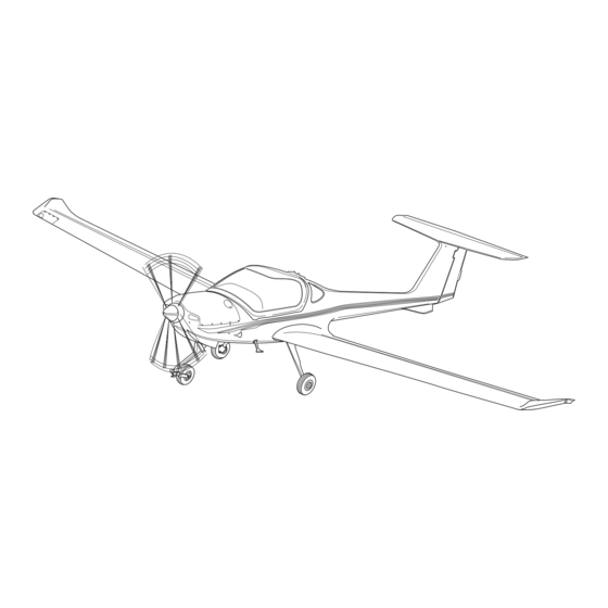
- Page 35 DA20-C1 Flight Manual General CHAPTER 1 GENERAL TABLE OF CONTENTS PAGE INTRODUCTION .................. 3 CERTIFICATION BASIS ............... 3 WARNINGS, CAUTIONS AND NOTES ..........4 THREE-VIEW-DRAWING OF THE AIRPLANE ........5 DIMENSIONS ..................6 1.5.1 Overall Dimensions ..............6 1.5.2 Wing ..................6 1.5.3...
- Page 36 General DA20-C1 Flight Manual PAGE 1.11.3 Powerplant ................12 1.11.4 Flight Performance and Flight Planning ........13 1.11.5 Weight and Balance ..............13 1.11.6 Equipment ................14 1.11.7 Miscellaneous .................14 1.12 CONVERSION FACTORS ..............15 1.12.1 Length or Altitude ..............15 1.12.2 Speed ..................15 1.12.3 Pressure ..................15 1.12.4 Weight ..................15...
- Page 37 For permissible accessories refer to the Equipment List, Section 6.5. CERTIFICATION BASIS The DA20-C1 has been approved by Transport Canada in accordance with the Canadian Airworthiness Manual (AWM) Chapter 523-VLA., Type Certificate No. A-191. Category of Airworthiness:...
- Page 38 General DA20-C1 Flight Manual 1.3 WARNINGS, CAUTIONS AND NOTES The following definitions apply to warnings, cautions, and notes used in the Flight Manual:: WARNING A WARNING MEANS THAT THE NON-OBSERVATION OF THE CORRESPONDING PROCEDURE LEADS TO AN IMMEDIATE OR IMPORTANT DEGRADATION IN FLIGHT SAFETY.
- Page 39 DA20-C1 Flight Manual General THREE-VIEW-DRAWING OF THE AIRPLANE 10890 mm (35 ft 9 in) 1860 mm (6 ft 1 in) 7240 mm (23 ft 9 in) 1600 mm 2160 mm (5 ft 3 in) (7 ft 1 in) Page 1 - 5...
- Page 40 General DA20-C1 Flight Manual 1.5 DIMENSIONS 1.5.1 Overall Dimensions Span: 35 ft 9 in (10.89 m) Length: 23 ft 9 in (7.24 m) Height: 7 ft 1 in (2.16 m) 1.5.2 WING Airfoil: Wortmann FX 63-137/20 HOAC Wing Area: 125 sq ft (11.6 m2) Mean Aerodynamic Chord (MAC): 3 ft 6.9 in (1.09 m)
- Page 41 DA20-C1 Flight Manual General ENGINE Continental IO 240, naturally aspirated, 4 cylinder, 4 stroke-engine, fuel injected, horizontally opposed, air cooled. Propeller drive direct from engine crankshaft. Displacement: 239.8 cu.in. (3.9 liters) Output Power: 125 hp (93.2 kW) 2800 RPM PROPELLER...
- Page 42 General DA20-C1 Flight Manual 1.9 LUBRICANT AND COOLANT 1.9.1 Lubricant Use only the lubricating oils conforming to TCM specifications listed in Service Information Letter SIL99-2B. See Table 1 below for approved brands. Table 1 Qualified Lubricating Oil – Ashless Dispersant (SAE J 1899)
- Page 43 DA20-C1 Flight Manual General The viscosity should be selected according to the various climatic conditions using Table 2. NOTE When selecting oil, the supplier’s documentation must be consulted to make sure that the oil is appropriate for the climactic conditions.
- Page 44 General DA20-C1 Flight Manual 1.10 WEIGHT Maximum Ramp Weight : 1770 lbs (803 kg) Maximum Take-off Weight : 1764 lbs (800 kg) Maximum Landing Weight : 1764 lbs (800 kg) Empty Weight : See Chapter 6 Maximum Weight in Baggage Compartment...
- Page 45 DA20-C1 Flight Manual General 1.11 LIST OF DEFINITIONS AND ABBREVIATIONS 1.11.1 Airspeeds CAS: Calibrated Airspeed. Indicated airspeed, corrected for installation and instrument errors. CAS equals TAS at standard atmospheric conditions (ISA) at MSL. Ground Speed. Speed of the airplane relative to the ground.
- Page 46 General DA20-C1 Flight Manual 1.11.2 Meteorological Terms AGL: Above Ground Level Indicated Pressure Altitude reading with altimeter set to 1013.25 hPa Altitude: (29.92 inHg). ISA: International Standard Atmosphere at which air is identified as a dry gas. The temperature at mean sea level is 15°...
- Page 47 DA20-C1 Flight Manual General 1.11.4 Flight Performance and Flight Planning Demonstrated The maximum speed of the crosswind component at Crosswind which the manoeuvrability of the airplane during Component: take-off and landing has been demonstrated during type certification test flights. Service Ceiling: The altitude at which the maximum rate of climb is 0.5 m/s (100 ft/min.)
- Page 48 General DA20-C1 Flight Manual Empty Weight: Weight of the airplane including unusable fuel, all operating fluids and maximum amount of oil. Useful Load: The difference between take-off weight and empty weight. Maximum Take-off Maximum weight permissible for take-off. Weight: 1.11.6 Equipment...
- Page 49 DA20-C1 Flight Manual General 1.12.5 Volume 1 [US gallon] = 3.785 [liters] 1 [Imperial gallon] = 4.546 [liters] CONVERSION CHART - LITERS/US GALLONS Liter US Gallon US Gallon Liter 15.1 22.7 30.3 37.9 45.4 10.6 53.0 11.9 60.6 13.2 68.1 15.9...
- Page 50 General DA20-C1 Flight Manual Intentionally left blank DOC # DA202-C1 Page 1 - 16 May 15, 2012 Revision 26...
- Page 51 DA20-C1 Flight Manual Operating Limitations CHAPTER 2 OPERATING LIMITATIONS TABLE OF CONTENTS PAGE INTRODUCTION ................... 3 AIRSPEED LIMITATIONS..............4 AIRSPEED INDICATOR MARKINGS ............ 4 POWER PLANT LIMITATIONS.............. 5 2.4.1 Engine ..................5 2.4.2 Additional for aircraft equipped with altitude compensating fuel system............6 2.4.3...
- Page 52 Operating Limitations DA20-C1 Flight Manual PAGE 2.16 DEMONSTRATED CROSSWIND COMPONENT ........30 2.17 TEMPERATURE LIMITS ..............30 Page 2 - 2 May 15, 2012 DOC # DA202-C1 DOT Approved Revision 26...
- Page 53 DA20-C1 Flight Manual Operating Limitations INTRODUCTION Chapter 2 of this Flight Manual comprises of the operating limitations, instrument markings, airspeed indicator markings, and the limitation placards which are necessary for the safe operation of the airplane, its engine, and standard systems and equipment.
- Page 54 Operating Limitations DA20-C1 Flight Manual AIRSPEED LIMITATIONS Speed KIAS Remarks Do not make full or abrupt control movement above this speed. Under certain conditions the airplane may be overstressed by full control Maneuvering Speed movement. Maximum Flap Extended Speed Do not exceed this speed with flaps in take-off (Takeoff) position.
- Page 55 DA20-C1 Flight Manual Operating Limitations POWER-PLANT LIMITATIONS 2.4.1 Engine (a) Engine Manufacturer : Textron Lycoming (b) Engine Type Designation : IO-240-B (c) Engine Operating Limitations Max. T/O Power (5 min.) : 125 BHP / 93.2 kW Max. Permissible T/O RPM : 2800 RPM Max.
- Page 56 Operating Limitations DA20-C1 Flight Manual (g) Fuel Specifications Approved Fuel Grades : AVGAS 100LL or 100 (h) Oil Grades : Reference TCM IO-240-B operator and installation manual (form X30620) or TCM specification MHS-24. Refer to Chapter 1, Section 1.9.1. Lubricant, Table 1.
-
Page 57: Powerplant Instrument Markings
DA20-C1 Flight Manual Operating Limitations POWERPLANT INSTRUMENT MARKINGS Powerplant instrument markings and their color code significance are shown below: Green Arc/ Red Line/ Normal Yellow Arc/ Red Line/ Instrument Lower Limit Operating Caution Range Upper Limit Range Tachometer 700 - 2800 RPM... - Page 58 Operating Limitations DA20-C1 Flight Manual MISCELLANEOUS INSTRUMENT MARKINGS Green Arc/ Yellow Arc/ Red Line/ = Normal Red Line/ Instrument = Caution = Lower Limit Operating = Upper Limit Range Range Voltmeter 8 - 12 Volts 12.5 - 16 Volts 11 - 12.5 Volts 16.1 Volts...
- Page 59 DA20-C1 Flight Manual Operating Limitations CENTER OF GRAVITY Points Gross Weight Arm (aft of datum) (lbs) (kgs) (in) 1653 7.95 .202 1764 8.07 .205 1764 12.16 .309 1653 12.48 .317 WARNING EXCEEDING THE CENTER OF GRAVITY LIMITATIONS REDUCES THE MANEUVERABILITY AND STABILITY OF THE AIRPLANE.
- Page 60 Operating Limitations DA20-C1 Flight Manual APPROVED MANEUVERS This airplane is certified in the UTILITY Category in accordance with Canadian Airworthiness Manual Chapter 523-VLA. Permissible Utility Category Maneuvers: (a) All normal flight maneuvers (b) The following maneuvers in which the angle of bank is not more than 60°:...
- Page 61 DA20-C1 Flight Manual Operating Limitations 2.10 MANEUVERING LOAD FACTORS Table of structural maximum permissible load factors: with flaps in T/O at V or LDG position Positive + 4.4 + 4.4 + 2.0 Negative - 2.2 - 2.2 WARNING EXCEEDING THE MAXIMUM LOAD FACTORS WILL RESULT IN OVERSTRESSING OF THE AIRPLANE.
- Page 62 Operating Limitations DA20-C1 Flight Manual 2.13 KINDS OF OPERATION Flights are permissible in accordance with visual flight rules. Minimum Equipment, Flight and Navigation Instruments: Airspeed Indicator Altimeter Attitude Gyro (Artificial Horizon) (Mandatory Night operations EASA member countries) Magnetic Compass Turn and Bank Indicator...
- Page 63 DA20-C1 Flight Manual Operating Limitations 2.14 FUEL Fuel Capacity Total Fuel Quantity: : 24.5 US gal. (93.0 liters) Usable Fuel: : 24.0 US gal. (91.0 liters) Unusable Fuel: : 0.5 US gal. (2.0 liters) 2.15 PLACARDS The following placards must be installed: 1.
- Page 64 Operating Limitations DA20-C1 Flight Manual 2. On the Flap Controller. 3. On the upper instrument panel surround. 4. On the instrument panel below the airspeed indicator. 5. On the instrument panel below the tachometer. 6. On the fuel quantity indicator.
- Page 65 DA20-C1 Flight Manual Operating Limitations 9. On the lower left side of the instrument panel above the switches. With Aspen Avionics Page 2 - 15 DOC # DA202-C1 May 15, 2012 DOT Approved Revision 26...
- Page 66 Operating Limitations DA20-C1 Flight Manual 10. On the instrument panel above the individual circuit breakers. NOTE Placard information will vary depending on installed equipment in the aircraft. Page 2 - 16 May 15, 2012 DOC # DA202-C1 DOT Approved Revision 26...
- Page 67 DA20-C1 Flight Manual Operating Limitations 11. On the lower left side of the instrument panel. (a) With Aspen installed. 12. On the upper left corner of the instrument panel. Page 2 - 17 DOC # DA202-C1 May 15, 2012 DOT Approved...
- Page 68 Operating Limitations DA20-C1 Flight Manual 13. On the exterior of the canopy frame on the L/H side and on the interior of the canopy frame on the R/H side. (No longer installed after S/N C0121) 14. On the exterior of the canopy frame on the R/H side and on the interior of the canopy frame on the L/H side.
- Page 69 DA20-C1 Flight Manual Operating Limitations 17. On the exterior of the canopy frame on the L/H side, If equipped with an outside handle. 18. On the exterior of the canopy frame on the R/H side, If equipped with an outside handle.
- Page 70 Operating Limitations DA20-C1 Flight Manual 20. On the exterior of the canopy frame on the R/H side, If equipped with an outside handle. (No longer installed after S/N C0149). 21. On the interior of the canopy frame on the L/H side and R/H side.
- Page 71 DA20-C1 Flight Manual Operating Limitations 23. On the interior of the canopy frame on the R/H and L/H side. (If equipped with an outside handle) On the L/H side of the canopy sill. On the R/H side of the canopy sill 25.
- Page 72 Operating Limitations DA20-C1 Flight Manual 27. On the fuselage (belly), near the center line between the wings. 28. On the underside of the fuselage (belly) to the left just forward of the wing trailing edge. 29. On the inside of the oil filler door.
- Page 73 DA20-C1 Flight Manual Operating Limitations 31. Under each wing and on the tail skid. 32. On the underside of the fuselage (belly) near the L/H wing trailing edge. 33. On the L/H side of the fuselage below the vertical stabilizer.
- Page 74 Operating Limitations DA20-C1 Flight Manual 35. On the upper engine cowling behind the propeller spinner. 36. Around the stall warning hole in the left wing. 37. Around the pilot/co-pilot headset jacks on the back rest. 38. Next to the ELT (if installed) to indicate the switch position.
- Page 75 DA20-C1 Flight Manual Operating Limitations 40. On the L/H side of the baggage compartment. 41. On the R/H side of the center console under the throttle. 42. On the brake fluid reservoirs. Page 2 - 25 DOC # DA202-C1 May 15, 2012...
- Page 76 Operating Limitations DA20-C1 Flight Manual 43. On the engine controls on the center console. or (b) or (c) or (d) 44. On the center console on the heating and parking brake controls. or (b) Page 2 - 26 May 15, 2012...
- Page 77 DA20-C1 Flight Manual Operating Limitations 45. On the left side of the instrument panel near the top. 46. On the engine controls for aircraft with center console mounted Fuel Selector. 47. On the instrument panel on Aircraft equipped with supplemental lighting (MOD 32).
- Page 78 Operating Limitations DA20-C1 Flight Manual 48. On fuel shut-off handle on R/H side of the center console. For aircraft with instrument panel mounted fuel selector. Around the ignition switch on Optional Ignition Switch the instrument panel. (Push-to-Start Feature) 50. On the back-rest on the right side.
- Page 79 DA20-C1 Flight Manual Operating Limitations 52. Adjacent to the flap controller. (T/O) 100 KTS. (LDG) 78 KTS. 53. On the instrument panel. If equipped with altitude compensating fuel pump. 54. On the instrument panel. If equipped with altitude compensating fuel pump.
- Page 80 Operating Limitations DA20-C1 Flight Manual 2.16 DEMONSTRATED CROSWIND COMPONENT The maximum demonstrated crosswind component is 20 kts. (37 km/h). 2.17 TEMPERATURE LIMITS CAUTION AIRCRAFT WITH OTHER THAN WHITE UNDERSIDES. PARKING THE AIRCRAFT OVER A LIGHT COLOURED REFLECTIVE SURFACE CONDITIONS OF BRIGHT SUNLIGHT, PARTICULARLY AT HIGH OAT, IS NOT RECOMMENDED.
- Page 81 DA20-C1 Flight Manual Emergency Procedures CHAPTER 3 EMERGENCY PROCEDURES TABLE OF CONTENTS PAGE INTRODUCTION ..................3 AIRSPEEDS DURING EMERGENCY PROCEDURES......3 EMERGENCY PROCEDURES - CHECKLISTS........4 3.3.1 Engine Failures ............... 4 3.3.2 Gliding ..................9 3.3.3 Emergency Landing ..............9 3.3.4 Fire ..................12 3.3.5...
- Page 82 DA20-C1 Flight Manual Emergency Procedures Intentionally left blank DOC # DA202-C1 Page 3 - 2 May 15, 2012 Revision 26 DOT Approved...
- Page 83 DA20-C1 Flight Manual Emergency Procedures INTRODUCTION The following chapter contains check-lists as well as descriptions of the recommended procedures in case of an emergency. However, engine failure or other airplane related emergency situations will most likely never occur if the mandatory pre-flight check and maintenance are performed properly.
- Page 84 DA20-C1 Flight Manual Emergency Procedures EMERGENCY PROCEDURES - CHECKLISTS 3.3.1 Engine Failures (a) Engine Failure during Take-off Run (1) Throttle............IDLE (2) Brakes ............as required (3) Flaps ............CRUISE (4) Mixture ............IDLE CUT-OFF (5) Ignition Switch ..........OFF (6) GEN/BAT Master Switch ......OFF...
- Page 85 DA20-C1 Flight Manual Emergency Procedures SHORTLY BEFORE LANDING (8) Mixture ............IDLE CUTOFF (9) Fuel Shut-off Valve ........CLOSED (10)Ignition Switch ..........OFF (11)Flaps ............as required (12)GEN/BAT Master Switch ......OFF ENGINE INOPERATIVE Perform emergency landing according to paragraph 3.3.3.
- Page 86 DA20-C1 Flight Manual Emergency Procedures LOSS OF OIL PRESSURE (1) Oil Temperature ......... check (2) If Oil Pressure drops below ......land at the nearest suitable Green Arc above 2100RPM......airport. (3) If Oil Pressure drops below ......reduce throttle to minimum Green Arc and oil temperature ....required power and land as...
- Page 87 DA20-C1 Flight Manual Emergency Procedures CAUTION DO NOT ENGAGE STARTER IF PROPELLER IS WINDMILLING. ENGINE DAMAGE MAY RESULT. The propeller will continue to windmill as long as the airspeed is at least 60 KIAS. RESTARTING THE ENGINE WITH PROPELLER WINDMILLING (1) Airspeed (VIAS) .........
- Page 88 DA20-C1 Flight Manual Emergency Procedures RESTARTING THE ENGINE WITH PROPELLER AT FULL STOP (1) Airspeed ............. 73 kts. (2) Electrically Powered Equipment ....OFF (3) GEN/BAT Master Switch ......ON (4) Mixture ............FULL RICH (5) Fuel shut off valve ........OPEN (6) Fuel Pump ..........ON (7) Fuel Prime ..........ON...
- Page 89 DA20-C1 Flight Manual Emergency Procedures 3.3.2 Gliding (a) Wing Flaps ............CRUISE (b) Airspeed at 1764 lbs (800 kg) ......73 KIAS (c) Glide Ratio 11:1 Example: For every 1000 feet of altitude the aircraft can move forward 11,000 feet or 1.8 NM (3.4 km).
- Page 90 DA20-C1 Flight Manual Emergency Procedures (b) Precautionary Landing with Engine Power Available NOTE A precautionary landing would be required if continuing the flight would endanger the aircraft or its occupants. Circumstances, including mechanical defects, low fuel quantity or deteriorating weather conditions could require a precautionary landing.
- Page 91 DA20-C1 Flight Manual Emergency Procedures (13)Final Approach: (A) Mixture ..........FULL RICH (B) Throttle ..........as required (C) Fuel Pump ........... ON (D) Wing Flaps .......... LDG (E) Airspeed ..........55 KIAS (14)Touch-down is to be made with minimum airspeed, nose wheel should be kept above ground as long as possible.
- Page 92 DA20-C1 Flight Manual Emergency Procedures 3.3.4 Fire (a) Engine Fire during Engine-Start-Up on the Ground (1) Fuel Shut-off Valve ........CLOSED (2) Cabin Heat ..........CLOSED (3) Mixture ............IDLE CUTOFF (4) GEN/BAT Master Switch ......OFF (5) Ignition Switch ..........OFF (6) Evacuate Airplane immediately (b) Engine Fire during Flight (1) Fuel Shut-off Valve ........
- Page 93 DA20-C1 Flight Manual Emergency Procedures (c) Electrical Fire including Smoke during Flight (1) GEN/BAT Master Switch ......OFF (2) Cabin Air ............ OPEN (3) Fire Extinguisher ........use only if smoke development continues. CAUTION IF FIRE EXTINGUISHER IS USED, THE CABIN MUST BE VENTILATED.
- Page 94 DA20-C1 Flight Manual Emergency Procedures (13)Circuit Breakers ..........Push to activate systems as required. (14)Radio ............ON (15)Land as soon as possible. (d) Electrical Fire including Smoke on the Ground (1) GEN/BAT Master Switch ......OFF IF ENGINE IS RUNNING: (2) Throttle ............IDLE (3) Mixture ............IDLE CUTOFF...
- Page 95 DA20-C1 Flight Manual Emergency Procedures 3.3.5 Icing Unintentional Flight Into Icing Area (a) Leave icing area (through change of altitude or change of flight direction to reach area with higher outside air temp). (b) Continue to move control surfaces to maintain their moveability.
- Page 96 DA20-C1 Flight Manual Emergency Procedures 3.3.6 Recovery from Unintentional Spin (a) Throttle ............... IDLE (b) Rudder ............... fully applied opposite direction of spin (c) Control Stick ............ease forward (d) Rudder ............... neutral, after rotation stopped (e) Wing Flaps ............CRUISE (f) Elevator ..............
- Page 97 DA20-C1 Flight Manual Emergency Procedures 3.3.8 Electrical Power Failure (a) Total Electrical Power Failure (1) Battery Circuit Breaker ....... If tripped, reset (2) GEN/BAT Master Switch ......check ON (3) Master Switch ..........OFF if power not restored (4) If Unsuccessful ........... Land at nearest suitable airport (b) Generator Failure GEN.
- Page 98 DA20-C1 Flight Manual Emergency Procedures (c) Low Voltage Indication (needle in yellow Arc) LOW VOLTAGE INDICATION (NEEDLE IN YELLOW ARC) WHILE AIRPLANE IS ON THE GROUND (1) Engine RPM ..........Increase RPM until needle is in the Green Arc. This should occur before exceeding 1100 RPM.
- Page 99 DA20-C1 Flight Manual Emergency Procedures 3.3.9 Flap System Failure Flap Position Indicator Failure (a) Visual check of the flap position (b) Select airspeed within the range of the white arc marked on the airspeed indicator (c) Check all positions of the flap toggle switch (flap stops are fail-safe) (d) Modify approach and landing as follows: (1) only CRUISE available: ......- raise approach speed by 10 kts...
- Page 100 DA20-C1 Flight Manual Emergency Procedures 3.3.11 Avionics System Failure TOTAL AVIONICS FAILURE: (a) Check Avionics Master Circuit......If popped, press and monitor Breaker status. If it pops again, land at the nearest suitable airport. (b) Check Avionics Master Switch ......Toggle avionics master switch,...
- Page 101 DA20-C1 Flight Manual Emergency Procedures 3.3.12 Trim System Failure STUCK TRIM: (a) Circuit breaker ............check, press if breaker is tripped (b) Rocker switch .............depress in both directions, wait 5 minutes, try again NOTE Full range of travel is available for elevator, but expect higher forces on control stick.
- Page 102 DA20-C1 Flight Manual Emergency Procedures 3.3.13 Instrument Panel Lighting Failure (a) Rocker Switch, map light ........ON (b) Rocker Switch, I-panel lighting ......Cycle Rocker Switch OFF-ON (c) Dimming Control ..........Turn fully clockwise (d) Internal Lighting Circuit Breaker ......If tripped, reset (e) If NOT Successful ..........
- Page 103 Normal Operating DA20-C1 Flight Manual Procedures CHAPTER 4 NORMAL OPERATING PROCEDURES TABLE OF CONTENTS PAGE INTRODUCTION .................. 3 AIRSPEEDS FOR NORMAL flight OPERATION ........3 STRUCTURAL TEMPERATURE INDICATOR ........4 NORMAL OPERATION CHECKLIST ............ 5 4.4.1 Preflight Inspection ............... 5 (a) In-Cabin Check..............
- Page 104 Normal Operating Procedures DA20-C1 Flight Manual PAGE 4.4.11 Landing Approach ..............24 4.4.12 Balked Landing ..............25 4.4.13 After Landing ...............25 4.4.14 Engine Shut-down ...............25 4.4.15 Flight in Rain ................26 4.4.16 Spinning ................27 (a) Spin Entry..............27 (b) Recovery from Spinning ..........28 4.4.17 Idle Power Operations ............29...
- Page 105 Normal Operating DA20-C1 Flight Manual Procedures INTRODUCTION Chapter 4 contains checklists and describes extended procedures for the normal operation of the airplane. AIRSPEEDS FOR NORMAL FLIGHT OPERATION Unless stated otherwise, the following table contains the applicable airspeeds for maximum take-off and landing weight. The airspeeds may also be used for lower flight weights.
- Page 106 Normal Operating Procedures DA20-C1 Flight Manual STRUCTURAL TEMPERATURE INDICATOR A structural temperature indicator, installed on the spar bridge, indicates when the structural temperature limitation is exceeded (refer to Section 2.17). The indicator need only be checked if the OAT exceeds 38º C (100º F).
- Page 107 Normal Operating DA20-C1 Flight Manual Procedures NORMAL OPERATION CHECKLIST 4.4.1 Preflight Inspection (a) In-Cabin Check (1) Structural Temperature Indicator .....check that Structural Temperature (if OAT exceeds 38º C (100º F)) does not exceed 55º C (131º F) (2) Airplane Documents ........check (3) Flight Control Lock ........removed...
- Page 108 Normal Operating Procedures DA20-C1 Flight Manual (18)Wing Flaps (Indicator- ......check, extend and retract fully andflap Actuation) (19)Trim and Flap Indicator Lights ....operational and dimmable (20)Exterior Lights ......... operational as required (21)GEN/BAT Master Switch ......OFF (22)Foreign Object Inspection ....... done (23)Emergency Locator Transmitter (ELT): ARTEX ELT-200......
- Page 109 Normal Operating DA20-C1 Flight Manual Procedures (b) Walk Around Check and Visual Inspection Page 4 - 7 DOC # DA202-C1 May 15, 2012 Revision 26 DOT Approved...
- Page 110 Normal Operating Procedures DA20-C1 Flight Manual CAUTION VISUALLY INSPECT FOLLOWING CONDITIONS: DEFECTS, CONTAMINATION, CRACKS, DELAMINATIONS, EXCESSIVE PLAY, INSECURE OR IMPROPER MOUNTING AND GENERAL CONDITION. ADDITIONALLY, CHECK THE CONTROL SURFACES FOR FREEDOM OF MOVEMENT. CAUTION SET THE PARKING BRAKE PRIOR TO REMOVING THE WHEEL CHOCKS.
- Page 111 Normal Operating DA20-C1 Flight Manual Procedures (G) Aileron Balancing Weight ......visual inspection (H) Aileron including Inspection Panel ...visual inspection (I) Wing Flap including Inspection Panel ..visual inspection (3) Fuselage (A) Skin ............visual inspection (B) Fuel Tank Vent ..........check (C) Fuel Drains ..........drain water (D) Structural Temperature Indicator ....
- Page 112 Normal Operating Procedures DA20-C1 Flight Manual (6) Right Main Landing Gear (A) Landing Gear Strut ........visual inspection (B) Wheel Fairing ...........visual inspection (C) Tire Pressure (33 psi / 2.3 bar) ....check (D) Tire, Wheel, Brake ........visual inspection (E) Wheel Chocks ..........remove (7) Nose (A) Oil .............check level by using dipstick.
- Page 113 Normal Operating DA20-C1 Flight Manual Procedures 4.4.2 Before Starting Engine CAUTION BEFORE STARTING THE ENGINE, THE CANOPY MUST BE CLOSED AND LATCHED. THE RED HANDLES MUST BE MOVED FULLY FORWARD. AFTER STARTING THE ENGINE, THE CANOPY MUST STAY IN THE CLOSED AND LATCHED POSITION UNTIL THE ENGINE IS SHUT DOWN.
- Page 114 Normal Operating Procedures DA20-C1 Flight Manual 4.4.3 Starting Engine (a) Starting Engine Cold NOTE It is recommended that the engine be preheated if it has been cold soaked for 2 hours or more at temperatures of -4º C (25º F) or less.
- Page 115 Normal Operating DA20-C1 Flight Manual Procedures (7) Throttle ............FULL for prime prime seconds minimum before starting) (8) Throttle ............Full IDLE to ¼ inch OPEN (adjust as required) (9) Ignition Switch ..........START, hold until engine starts or for 10 seconds maximum (if...
- Page 116 Normal Operating Procedures DA20-C1 Flight Manual NOTE Excessive priming can result in a flooded engine. To clear a flooded engine, turn off the fuel pump and fuel prime, open the throttle 1/2 to 1 inch and engage the starter. The engine should start for a short period and then stop.
- Page 117 Normal Operating DA20-C1 Flight Manual Procedures (b) Starting Engine Warm (1) Throttle ............IDLE (2) Mixture ............FULL RICH (3) Toe Brakes ..........hold (4) Propeller Area ..........clear WARNING MAKE SURE THAT THE PROPELLER AREA IS CLEAR. CAUTION DO NOT ENGAGE THE STARTER IF THE PROPELLER IS MOVING.
- Page 118 Normal Operating Procedures DA20-C1 Flight Manual NOTE If the optional Push-to-Start ignition switch is installed, then additional “PUSH” action is required after the ignition switch is turned to the START position when implementing start. (10)Starter Warning Light ......... illuminated while ignition is in...
- Page 119 Normal Operating DA20-C1 Flight Manual Procedures NOTE Oil Pressure may advance above the green arc until Oil Temperature reaches normal operating temperatures. Regulate warm up RPM to maintain pressure below 100 psi limit. At ambient temperatures below 32º F (0º C) DO NOT apply full power if oil pressure is above 70 psi.
- Page 120 Normal Operating Procedures DA20-C1 Flight Manual 4.4.5 Taxiing (a) Brake ..............check (b) Mixture ............. FULL RICH (c) Throttle ............. As required (d) Direction Control ..........check (e) Flight Instruments and Avionics ....... check (f) Compass ............check CAUTION AT HIGH ENGINE RPM THE PROPELLER CAN BE DAMAGED BY LOOSE SAND, GRAVEL OR WATER.
- Page 121 Normal Operating DA20-C1 Flight Manual Procedures 4.4.6 Before Take-off (Engine Run-up) NOTE For OAT’s less than -5º F (-20º C) turn cabin heat on for at least 10 minutes prior to take-off. (a) Brakes .............. apply (b) Safety Belts ............fastened (c) Canopy .............
- Page 122 Normal Operating Procedures DA20-C1 Flight Manual (r) Oil Pressure ............. 30-60 psi (s) Vacuum Gauge (if installed) ......within green range (t) Throttle ............. IDLE (975 RPM Minimum, for aircraft with altitude compensating fuel system) (u) Mixture ............. Move slowly toward lean cut off...
- Page 123 Normal Operating DA20-C1 Flight Manual Procedures 4.4.7 Take-off (a) Fuel Prime ............check OFF (b) Fuel Pump ............check ON (c) Mixture .............. check FULL RICH (d) GEN/BAT Master Switch ........check ON (e) Ignition Switch ..........check BOTH (f) Wing Flaps ............check T/O (g) Trim ..............
- Page 124 Normal Operating Procedures DA20-C1 Flight Manual 4.4.8 Climb (a) Mixture .............. FULL RICH NOTE For aircraft without the altitude compensating fuel pump, at full throttle settings with power less than 75%, it is necessary to lean the engine with the mixture control. It should be noted that with the engine set to full throttle, it can produce less than 75% power, depending on pressure altitude.
- Page 125 Normal Operating DA20-C1 Flight Manual Procedures 4.4.10 Descent (a) Flight Instruments and Avionics ....... adjust (b) Fuel Pump ............ON (c) Mixture .............. FULL RICH (d) Throttle ............. as required CAUTION ADJUST DESCENT PROFILE (ANGLE, AIRSPEED, AND POWER) AS REQUIRED TO AVOID ENGINE SHOCK COOLING.
- Page 126 Normal Operating Procedures DA20-C1 Flight Manual 4.4.11 Landing Approach (a) Seat Belts ............fastened (b) Lights ..............as required (c) GEN/BAT Master Switch ........check ON (d) Ignition Switch ..........check BOTH (e) Fuel Pump ............check ON (f) Mixture ............. FULL RICH (g) Throttle .............
- Page 127 Normal Operating DA20-C1 Flight Manual Procedures 4.4.12 Balked Landing (a) Throttle ............. FULL (b) Mixture .............. FULL RICH (c) Wing Flaps ............T/O (d) Airspeed ............58 KIAS 4.4.13 After Landing (a) Throttle ............. as required (b) Mixture .............. FULL RICH (c) Wing Flaps ............
- Page 128 Normal Operating Procedures DA20-C1 Flight Manual 4.4.15 Flight in Rain NOTE Flight performance might be reduced, especially for the T/O distance and the maximum horizontal air speed. The influence on flight characteristics of the airplane is negligible. Flights through heavy rain should be avoided due to the reduced visibility.
- Page 129 Normal Operating DA20-C1 Flight Manual Procedures 4.4.16 Spinning (a) Spin Entry (1) Loose Items ..........stowed (2) Seat Belts ........... fastened (3) Altitude and Airspace ......... check (4) Fuel Pump ..........ON (5) Wing Flaps ..........CRUISE (6) Mixture ............FULL RICH (7) Throttle ............
- Page 130 Normal Operating Procedures DA20-C1 Flight Manual (b) Recovery from Spinning (1) Throttle ............IDLE (2) Rudder ............fully applied in opposite to direction of spin (3) Control Stick ..........ease stick forward until spinning stops (4) Rudder ............neutral, immediately...
- Page 131 Normal Operating DA20-C1 Flight Manual Procedures 4.4.17 Idle Power Operations NOTE Turn the fuel pump on for all low throttle operations, including taxiing and all flight operations when engine speed could fall below 1400 RPM (eg. stalls, descents, spins, landings, etc.).
- Page 132 Normal Operating DA20-C1 Flight Manual Procedures Intentionally left blank Page 4 - 30 May 15, 2012 DOC # DA202-C1 DOT Approved Revision 26...
- Page 133 DA20-C1 Flight Manual Performance CHAPTER 5 PERFORMANCE TABLE OF CONTENTS PAGE INTRODUCTION ................... 3 USE OF THE PERFORMANCE TABLES AND DIAGRAMS ....3 PERFORMANCE TABLES AND DIAGRAMS ........4 5.3.1 Airspeed System Calibration ..........4 5.3.2 Cruising Performance ............5 5.3.3...
- Page 134 Performance DA20-C1 Flight Manual Intentionally left blank DOC # DA202-C1 Page 5 - 2 May 15, 2012 Revision 26 DOT Approved...
- Page 135 DA20-C1 Flight Manual Performance INTRODUCTION This chapter contains the performance data required by the basis of certification. This data which has been approved by Transport Canada is marked ‘DOT Approved’ in the footer of the page. Where additional performance data has been provided, beyond the basis for certification, it has not been reviewed or approved by Transport Canada.
- Page 136 DA20-C1 Flight Manual Performance PERFORMANCE TABLES AND DIAGRAMS 5.3.1 Airspeed System Calibration Assumes zero indicator error. Table 1 - Airspeed System Calibration Flaps Cruise KIAS KCAS Flaps Take-Off (T/O) KIAS KCAS Flaps Landing (LDG) KIAS KCAS Example: CRUISE Flap KIAS = 90 kts, therefore KCAS = 92 kts from chart...
- Page 137 DA20-C1 Flight Manual Performance 5.3.2 Cruising Performance Maximum RPM is 2800. TEMPERATURE ( C) RPM X 100 TEMPERATURE ( F) Example: OAT: ........70° F Pressure Sltitude:....5000 ft Desired Power Setting: ..60% Result: Set RPM: ....... 2560 Figure 5.1 - Cruising Performance...
- Page 138 DA20-C1 Flight Manual Performance 5.3.3 Stall Speeds Configuration: Idle, most forward center of gravity, max. weight of 1764 lbs (800 kg). (This is the most adverse configuration) Table 2 - Stall Speeds Most Forward Center of Gravity Angle of Bank Flap 0°...
- Page 139 DA20-C1 Flight Manual Performance 5.3.4 Wind Components Maximum demonstrated crosswind component:..20 kts (37 km/h) Example: Wind Speed: ............11 kts (20 km/h) Angle between wind direction and flight direction:.. 30 degrees Headwind Component: ........... 9.5 kts (18 km/h) Crosswind Component: .......... 5.5 kts (10 km/h) Figure 5.2 - Wind Components...
- Page 140 DA20-C1 Flight Manual Performance 5.3.5 Take-off Distance Figure 5.3 - Take-off Distance DOC # DA202-C1 Page 5 - 8 May 15, 2012 Revision 26 DOT Approved...
- Page 141 DA20-C1 Flight Manual Performance 5.3.6 Climb Performance /Cruising Altitudes Max. Cruising Altitude (in standard conditions): ....13120 ft (4000 m) Best Rate-of-Climb Speed with Wing Flaps CRUISE ..75 KIAS CAUTION IN AIRPLANE OPERATIONS WITHOUT THE OPTIONAL WHEEL FAIRINGS INSTALLED, THE CLIMB PERFORMANCE IS REDUCED BY APPROXIMATELY 3%.
- Page 142 DA20-C1 Flight Manual Performance 5.3.7 Climb Performance / Take off Best Rate-of-Climb Speed with Wing Flaps T/O: ....68 KIAS Example: Pressure Altitude: ..........2000 ft OAT: ..............65° F Weight : ............1764 lbs Result: Climb performance: .......... 744 ft/min Figure 5.5 - Climb Performance / Take off...
- Page 143 DA20-C1 Flight Manual Performance 5.3.8 Cruising Speed (True Airspeed) Diagram for true airspeed (TAS) calculation at selected power level. CAUTION IN AIRPLANE OPERATIONS WITHOUT THE OPTIONAL WHEEL FAIRINGS INSTALLED, THE MAXIMUM CRUISING SPEED IS REDUCED BY APPROXIMATELY 5%.. Example: Pressure Altitude: ........6000 ft OAT: ............
- Page 144 DA20-C1 Flight Manual Performance 5.3.9 Maximum Flight Duration Table for calculation of the Maximum Flight Duration depending on fuel availability. Table 3 - Cruise Performance Table 20º C Below Standard Standard 10º C Above Standard Press Alt Temp Temperature Temp...
- Page 145 DA20-C1 Flight Manual Performance Cruise Performance Table - Continued 20º C Below Standard Standard 10º C Above Standard Press Alt Temp Temperature Temp %bhp KTAS %bhp KTAS %bhp KTAS 10,000 2800 2750 2700 2650 2600 12,000 2800 2750 2700 2650...
- Page 146 DA20-C1 Flight Manual Performance 5.3.10 Climb Performance / Balked Landing Conditions: Speed = 52 KIAS Wing Flaps in Landing Position (LDG) maximum take-off power CAUTION IN AIRPLANE OPERATIONS WITHOUT THE OPTIONAL WHEEL FAIRINGS INSTALLED, THE CLIMB PERFORMANCE IS REDUCED BY APPROXIMATELY 3%.
- Page 147 DA20-C1 Flight Manual Performance 5.3.11 Landing Distance Conditions: - Throttle at Idle - Maximum T/O Weight - Approach Speed ....... 55 KIAS - Level Runway, paved - Wing Flaps in Landing position (LDG) - Standard Setting, MSL Landing distance over a 50 ft (15 m) obstacle: ..approx. 1360 ft (414m) Landing roll distance: ..........
- Page 148 DA20-C1 Flight Manual Performance NOISE DATA Table 5 - Noise Data Noise Measurement Method Noise Value Maximum Allowable FAR36 Appendix G 71.7 dBA 75.7 dBA ICAO Annex 16, Appendix 6 74.4 dBA 80.1 dBA Paragraph 10.4(a) ICAO Annex 16, Appendix 6 75.25 dBA...
- Page 149 DA20-C1 Flight Manual Weight and Balance CHAPTER 6 WEIGHT AND BALANCE TABLE OF CONTENTS PAGE INTRODUCTION.....................3 AIRPLANE WEIGHING ...................4 WEIGHT AND BALANCE REPORT..............7 FLIGHT WEIGHT AND CENTER OF GRAVITY ..........9 EQUIPMENT LIST ..................13 Page 6 - 1 May 15, 2012...
- Page 150 Weight and Balance DA20-C1 Flight Manual Intentionally left blank May 15, 2012 DOC # DA202-C1 Page 6 - 2 Revision 26 DOT Approved...
- Page 151 DA20-C1 Flight Manual Weight and Balance INTRODUCTION To obtain the performance, flight characteristics and safe operation described in this Flight Manual, the airplane must be operated within the permissible weight and balance envelope as described in Chapter 2. It is the pilot's responsibility to adhere to the weight and balance limitations and to take into consideration the change of the center of gravity (CG) position due to fuel consumption.
- Page 152 DA20-C1 Flight Manual Weight and Balance AIRPLANE WEIGHING Pre-weighing conditions: - equipment must be in accordance with the airplane equipment list - brake fluid, lubricant (6 US qt / 5.7 liters) and - unusable fuel, included (2 liters unusable, 3.18 lbs/1.44 Kg)
- Page 153 DA20-C1 Flight Manual Weight and Balance Figure 6.1 - Longitudinal Leveling Diagram Legend: Arm - Datum to center line nose wheel Arm - Datum to C/L main wheels (LH and RH) Net weight - Nose wheel Net weight - Main wheels (LH and RH)
- Page 154 DA20-C1 Flight Manual Weight and Balance Model: DA20-C1 Serial Number _____________ Registration _____________ Data with reference to the Type Certificate Data Sheet and the Flight Manual Reference Datum: Leading edge of wing at root rib. Horizontal reference line: Wedge 1000:55.84, 2000mm (78.7 in) aft of the step in the fuselage at the canopy edge.
- Page 155 DA20-C1 Flight Manual Weight and Balance WEIGHT AND BALANCE REPORT The empty weight and Empty Weight CG position data determined prior to delivery of the airplane is the first entry in the Weight and Balance Report. Each change of the installed...
- Page 156 DA20-C1 Flight Manual Weight and Balance Figure 6.4 - Sample Weight and Balance Report DOC # DA202-C1 Page 6 - 8 May 15, 2012 Revision 26 DOT Approved...
- Page 157 DA20-C1 Flight Manual Weight and Balance FLIGHT WEIGHT AND CENTER OF GRAVITY The following data enables the pilot to operate the DA20-C1 within the required weight and center of gravity limitations. The following diagrams, Figure 6.5 Loading Plan Figure 6.6 Weight & Balance Diagram Figure 6.7 Calculation of Loading Condition...
- Page 158 DA20-C1 Flight Manual Weight and Balance Example: Pilot and Passenger: 359 lbs. (163 kg) Fuel 14.0 US gal. / 52.9 liters: 93 lbs. (42 kg) (6.01 lbs. per US gal./0.72 kg per liter) Result: Moment of Pilot and Passenger: 2021 in. lbs. (24.4 kgm) Moment of Fuel: 3017 in.
- Page 159 DA20-C1 Flight Manual Weight and Balance DA20-C1 (EXAMPLE) YOUR DA20-C1 Calculation of the Load Limits Weight [lbs] Moment [in.lbs] Weight [lbs] Moment [in.lbs] (Weight [kg]) ([kgm]) (Weight [kg]) ([kgm]) Empty Weight (use the data 1153 12562 for your airplane recorded in...
- Page 160 DA20-C1 Flight Manual Weight and Balance P E R MIS S IB LE F LIG HT - W E IG HT - MOME NT (kg m) 1764 1700 1600 1500 1400 1300 1200 9000 11000 13000 15000 17000 19000 21000 P E R MIS S IB LE F LIG HT - W E IG HT - MOME NT (in lbs ) See an example calculation of loading condition in Figure 6.7.
- Page 161 DA20-C1 Flight Manual Weight and Balance EQUIPMENT LIST The following table lists all the equipment available for this airplane. An Equipment Record of items installed in your specific airplane is included in the back of this manual. The equipment list comprises the following data: The item No.
- Page 162 DA20-C1 Flight Manual Weight and Balance Equipment List Item Part Description, Weight Number Manufacturer Part/Model No. lbs (kg) in (m) 22-001 Autopilot Turn Coordinator/Roll Computer -16.4 S-TEC 01260-12-0-14 (1.0) (-0.42) 22-002 Autopilot Pitch Computer -27.4 S-TEC 01261-54-14 (0.5) (-0.69) 22-003 Autopilot Roll Servo 43.5...
- Page 163 (6.9) (1.46) Battery, standard (S/N C0149, C0151 onwards) 15.3 Yuasa Y50N18L-A-CX (6.9) (-0.89) 24-005 EPU Installation (S/N C0149, C0151 onwards) Diamond -23.6 Service Bulletin # DAC1-24-06” (1.2) (-0.6) 24-006 Battery, B&C Specialty Products 22.5 BC100-1 (S/N C0001 to C0148, C0150) (10.2)
- Page 164 RH 22-3210-06-00 , LH 22-3210-05-00 (1.2) (0.70) Wheel Fairing, Nose Gear -44.8 20-3220-13-00 (1.2) (-1.14) 33-001 Recognition Light Kit Diamond Service Bulletin # DAC1-33-01 (1.1) 33-002 Light Dimmer Module 16.4 White Wire WW-LCM 001 (0.3) (-0.42) 33-003 Flood Light -16.4 Aero Enhancements (0.3)
- Page 165 DA20-C1 Flight Manual Weight and Balance Equipment List Item Part Description, Weight Number Manufacturer Part/Model No. lbs (kg) in (m) 34-002a Encoder -20.0 SSD 120-30N (0.2) (-0.51) 34-003 Nav Indicator -16.4 King KI 208 (0.5) (-0.42) 34-004 Outside Air Temperature Indicator (F) -15.5...
- Page 166 DA20-C1 Flight Manual Weight and Balance Equipment List Item Part Description, Weight Number Manufacturer Part/Model No. lbs (kg) in (m) 34-016 Artificial Horizon -16.4 Sigma Tek 23-501-06-16 (0.9) (-0.42) 34-017 Artificial Horizon -16.4 Sigma Tek 23-501-035-5 (1.0) (-0.42) 34-018 Directional Gyro -16.4...
- Page 167 DA20-C1 Flight Manual Weight and Balance Equipment List Item Part Description, Weight Number Manufacturer Part/Model No. lbs (kg) in (m) 34-031 GPS/Nav/Com 20.5 Garmin GNS 530 (3.8) (0.42) 34-032 Traffic Advisory System Processor 55.5 Avidyne 70-2420-7 TAS600 (3.1) (1.41) 34-033 Traffic Advisory System Antenna, Top 0.66...
- Page 168 Manufacturer Part/Model No. lbs (kg) in (m) 71-001 Heater 45.5 Tanis TAS100-29 (0.5) (1.16) 71-002 Winter Kit -33.5 Diamond Service Bulletin # DAC1-71-01 (0.2) (-0.85) 73-001 Fuel Pressure Indicator -15.5 22-7330-00-01 (0.1) (-0.39) 77-001 Cylinder Head Temp. Indicator -16.4 22-7720-00-00 (0.1)
- Page 169 DA20-C1 Flight Manual Airplane Description CHAPTER 7 DESCRIPTION OF THE AIRPLANE AND ITS SYSTEMS TABLE OF CONTENTS PAGE INTRODUCTION ...................5 AIRFRAME ....................5 7.2.1 Fuselage ................5 7.2.2 Wings ..................5 7.2.3 Empennage ................5 FLIGHT CONTROLS ................6 7.3.1 Trim System ................6 7.3.2 Flaps ..................6 7.3.3...
- Page 170 Airplane Description DA20-C1 Flight Manual PAGE LANDING GEAR SYSTEM ..............12 7.5.1 Wheel Brakes ..............12 7.5.2 Parking Brake ..............12 SEATS AND SAFETY BELTS ..............14 BAGGAGE COMPARTMENT .............14 CANOPY .....................15 POWERPLANT ..................17 7.9.1 Engine .................17 7.9.2 Engine Controls ..............18 7.9.3 Mixture Control ..............19 7.9.4...
- Page 171 DA20-C1 Flight Manual Airplane Description PAGE 7.11 ELECTRICAL SYSTEM ...............26 7.11.1 Power Supply ..............26 7.11.2 Ignition System ..............26 7.11.3 Electrical Powered Equipment ..........27 7.11.4 Voltmeter ................27 7.11.5 Ammeter ................27 7.11.6 Generator Warning Light .............27 7.11.7 Instruments ................27 7.11.8 Internal Lighting ..............28 7.12...
- Page 172 Airplane Description DA20-C1 Flight Manual Intentionally left blank DOC # DA202-C1 Page 7 - 4 May 15, 2012 Revision 26...
- Page 173 DA20-C1 Flight Manual Airplane Description INTRODUCTION Chapter 7 provides a description and operation of the airplane and its systems. Refer to Chapter 9, Supplements, for details of optional systems and equipment. AIRFRAME 7.2.1 Fuselage The GFRP-fuselage is of semi-monocoque construction. The fire protection cover on the fire wall is made from a special fire retarding ceramic fiber that is covered by a stainless steel plate on the engine side.
- Page 174 Airplane Description DA20-C1 Flight Manual FLIGHT CONTROLS The ailerons and elevator are actuated via push rods. The rudder is controlled using control cables. The flaps have three positions, CRUISE, T/O (take-off), LDG (landing), and are electrically operated. The switch is located on the instrument panel.
- Page 175 DA20-C1 Flight Manual Airplane Description 7.3.3 Flap Position Indicator The current flap position is indicated by three control lights beside the flap operating switch. Wing Flap Position Light Degrees CRUISE green 0 degrees yellow 15 degrees yellow 45 degrees When two lights are illuminated at the same time, the flaps are in-between positions.
- Page 176 Airplane Description DA20-C1 Flight Manual 7.3.5 Flight Control Lock A flight control lock, P/N 20-2770-00-00_1, is provided with each aircraft and should be installed whenever the aircraft is parked. See Figure 1, Installation and Removal of the Control Stick. CAUTION...
- Page 177 DA20-C1 Flight Manual Airplane Description (g) Adjust the straps as required. Straps should be tight to secure the controls properly. (h) TO REMOVE, push the Control Stick forward (to relieve strap tension). Unclip the straps and remove the Control Lock. Store in the aircraft's baggage compartment.
- Page 178 Airplane Description DA20-C1 Flight Manual INSTRUMENT PANEL Figure 7.2 - Instrument Panel Diagram DOC # DA202-C1 Page 7 - 10 May 15, 2012 Revision 26...
- Page 179 DA20-C1 Flight Manual Airplane Description Table 1 - Instrument Panel Components Item Description Item Description Item Description Item Description Vacuum Gauge Vertical Speed Ind. Throttle Lever Fuel Quantity Ind. Clock (optional) Fuel Mixture Lever EGT Indicator Magnetic Compass Air Vent...
- Page 180 Airplane Description DA20-C1 Flight Manual LANDING GEAR SYSTEM The landing gear system consists of the two main landing gear wheels mounted to aluminum spring struts and a 60° castering nose wheel. The suspension of the nose wheel is provided by an elastomer spring.
- Page 181 DA20-C1 Flight Manual Airplane Description Figure 7.3 - Brake System Schematic Diagram Page 7 - 13 May 15, 2012 DOC # DA202-C1 Revision 26...
- Page 182 Airplane Description DA20-C1 Flight Manual SEATS AND SAFETY BELTS The seats are removable to facilitate the maintenance and inspection of the underlying controls. Covers on the control sticks prevent loose objects from entering the control area. The seats have removable cushions.
- Page 183 DA20-C1 Flight Manual Airplane Description CANOPY CAUTION BEFORE STARTING THE ENGINE, THE CANOPY MUST BE CLOSED AND LATCHED. THE RED HANDLES MUST BE MOVED FULLY FORWARD. AFTER STARTING THE ENGINE, THE CANOPY MUST STAY IN THE CLOSED AND LATCHED POSITION UNTIL THE ENGINE IS SHUT DOWN.
- Page 184 Airplane Description DA20-C1 Flight Manual Figure 7.4 - Canopy DOC # DA202-C1 Page 7 - 16 May 15, 2012 Revision 26...
- Page 185 The engine is shut off by moving the mixture control to the idle cutoff position then turning the ignition switch to the off position. The DA20-C1 may be equipped with an optional altitude compensating fuel pump. A placard on the instrument panel indicates if this system is installed. With this system it is not necessary to manually lean the mixture with altitude.
- Page 186 Airplane Description DA20-C1 Flight Manual 7.9.2 Engine Controls The Mixture, Throttle, and Alternate Air Control levers are grouped together in the center console. The tension/friction for the controls can be adjusted using the friction knob located on the right side of the center console.
- Page 187 DA20-C1 Flight Manual Airplane Description 7.9.3 Mixture Control (a) Cruise The mixture control allows leaning of the fuel mixture to maximize fuel economy during cruise conditions. Teledyne Continental Motors specifies that above 75% of maximum rated power, the mixture must be set at FULL RICH. It should be...
- Page 188 Airplane Description DA20-C1 Flight Manual 7.9.5 Lubricating CAUTION NEVER OPERATE THE ENGINE WITH THE OIL FILLER CAP REMOVED. OBSERVE NORMAL PROCEDURES AND LIMITATIONS WHILE RUNNING ENGINE. The engine has high pressure wet sump lubrication. The oil is pumped by a mechanical, engine driven pump.
- Page 189 Fuel pressure is measured at the fuel distribution manifold and displayed on the fuel pressure indicator, which is calibrated in PSI. Some DA20-C1 aircraft also have a fuel vapor separator in the distribution manifold. These aircraft have a second vapor return line from the distribution manifold to the firewall.
- Page 190 Airplane Description DA20-C1 Flight Manual Figure 7.6 - Fuel System Schematic Diagram DOC # DA202-C1 Page 7 - 22 May 15, 2012 Revision 26...
- Page 191 THE FUEL SHUT-OFF VALVE SHOULD ONLY BE CLOSED FOR EMERGENCIES OR FUEL SYSTEM MAINTENANCE. There are two different versions of fuel shut-off valves in the DA20-C1. Version 1 The fuel shut-off valve is located on the cabin side of the firewall and is controlled by a handle on the right side center pedestal.
- Page 192 Airplane Description DA20-C1 Flight Manual 7.10.5 FUEL DIPSTICK A fuel dipstick, P/N 22-2550-14-00, is supplied with all aircraft to permit direct measurement of fuel level during the preflight check. On serial numbers C0056, C0066, C0067 and C0069 use fuel dipstick P/N 22-2550-17-00.
- Page 193 Airplane Description 7.10.6 ELECTRIC FUEL PUMP (PRIMING PUMP) OPERATION The DA20-C1 is equipped with a DUKES constant flow, vane type, two speed, and electric fuel pump. This pump emits an audible whine when it is switched on. (a) Fuel Prime The pump's high speed setting is used for priming the engine prior to engine start.
- Page 194 Airplane Description DA20-C1 Flight Manual 7.11 ELECTRICAL SYSTEM Simplified Schematic (see Figure 7.7) 7.11.1 Power Supply A 12 V battery is connected to the master bus via the battery circuit breaker (50 Amps). The 40 amp. generator is attached to the engine near the propeller hub.
- Page 195 DA20-C1 Flight Manual Airplane Description 7.11.3 Electrical Powered Equipment The individual consumers (e.g. Radio, Fuel Pump, Position Lights, etc.) are connected in series with their respective circuit breakers. See Figure 7.2 for an illustration of the instrument panel. 7.11.4 Voltmeter The voltmeter indicates the status of the electrical bus.
- Page 196 DA20-C1 Flight Manual 7.11.8 Internal Lighting The internal lighting of the DA20-C1 is provided by a lighting module located aft of the Pilot’s head and on the centerline of the aircraft. Included in this module are two panel illumination lights and one map light. The switches for the lights are located on the instrument panel.
- Page 197 DA20-C1 Flight Manual Airplane Description 7.12 PITOT AND STATIC PRESSURE SYSTEMS The pitot pressure is measured on the leading edge of a calibrated probe below the left wing. The static pressure is measured by the same probe. For protection against water and humidity, water sumps are installed within the line. These water sumps are accessible beneath the left seat shell.
- Page 198 Airplane Description DA20-C1 Flight Manual 7.14 AVIONICS The center of the instrument panel contains the radio and navigation equipment. The microphone key for the radio is installed in the control stick. There are two connectors for headsets on the backrest of the seat.
- Page 199 Handling, Care and DA20-C1 Flight Manual Maintenance CHAPTER 8 AIRPLANE HANDLING, CARE AND MAINTENANCE TABLE OF CONTENTS PAGE INTRODUCTION ..................3 AIRPLANE INSPECTION PERIOD ............3 AIRPLANE ALTERATIONS OR REPAIRS ..........3 GROUND HANDLING / ROAD TRANSPORT........4 8.4.1 Ground Handling ...............4 8.4.2 Parking ..................4 8.4.3...
- Page 200 Handling, Care and DA20-C1 Flight Manual Maintenance Intentionally left blank Page 8 - 2 May 15, 2012 DOC # DA202-C1 Revision 26...
- Page 201 Handling, Care and DA20-C1 Flight Manual Maintenance INTRODUCTION This Chapter contains factory-recommended procedures for proper ground handling and servicing of the airplane. It also identifies certain inspection and maintenance requirements which must be followed if the airplane is to retain its’...
- Page 202 Handling, Care and DA20-C1 Flight Manual Maintenance GROUND HANDLING / ROAD TRANSPORT 8.4.1 Ground Handling (a) Towing Forward The airplane is most easily and safely maneuvered by hand with the tow- bar attached to the nose wheel. See Figure 8.1 for installation of tow bar.
- Page 203 Handling, Care and DA20-C1 Flight Manual Maintenance (b) Moving Backward By following a simple procedure it is very easy to move the airplane backwards. CAUTION DO NOT PUSH OR LIFT ON THE SPINNER! CAUTION DO NOT PUSH ON CONTROL SURFACES! (1) Push down with one hand on the aft section of the fuselage near the vertical stabilizer, to lift the nose wheel.
- Page 204 Handling, Care and DA20-C1 Flight Manual Maintenance 8.4.3 Mooring The tail skid of the airplane has a tie down hole which can be used to moor airplane. Tie-down rings are also installed near the midpoint on each wing for tie-down mooring ropes.
- Page 205 DA20-C1 Flight Manual Maintenance 8.4.4 Jacking The DA20-C1 can be jacked at the two jack points located on the lower side of the fuselage's root ribs and at the tail fin. See Figure 8.3. Figure 8.3 - Jacking Point Locations...
- Page 206 Handling, Care and DA20-C1 Flight Manual Maintenance 8.4.5 Road Transport When transporting the airplane on the road, it is recommended that you use an open trailer. All airplane components must be stored on a cushioned surface and secured to avoid any movement during transport.
- Page 207 THE AIRCRAFT, EVER IN FUTURE, IS IN NEED OF STRUCTURAL REPAIR. To achieve the best flight characteristics for the DA20-C1, a clean external surface is most important. For this reason it is highly recommended that the airplane, especially the leading edge of the wings are kept clean at all times.
- Page 208 Handling, Care and DA20-C1 Flight Manual Maintenance 8.5.2 Canopy The DA20-C1 offers excellent vision through a large plexiglass canopy. It is essential that care be taken while cleaning the canopy, as it is easily scratched. If scratched, the vision will be reduced.
- Page 209 Handling, Care and DA20-C1 Flight Manual Maintenance GROUND DE-ICING Approved de-icing fluids are: Manufacturer Name Kilfrost TKS 80 Aeroshell Compound 07 Any Source AL-5 (DTD 406B) Remove the snow from the aircraft as follows: (a) Remove any snow from the airplane using a soft brush.
- Page 210 Handling, Care and DA20-C1 Flight Manual Maintenance Intentionally left blank Page 8 - 12 May 15, 2012 DOC # DA202-C1 Revision 26...
- Page 211 Supplements DA20-C1 Flight Manual CHAPTER 9 SUPPLEMENTS TABLE OF CONTENTS PAGE GENERAL ...................9-3 INDEX OF SUPPLEMENTS..............9-4 Page 9 - 1 DOC # DA202-C1 May 15, 2012 Revision 26...
- Page 212 Supplements DA20-C1 Flight Manual Intentionally left blank DOC # DA202-C1 Page 9 - 2 May 15, 2012 Revision 26...
- Page 213 Supplements DA20-C1 Flight Manual GENERAL This Chapter contains information regarding optional equipment which may be installed in your airplane. Individual supplements address each optional equipment installation. It is only necessary to maintain those supplements which pertain to your specific airplane’s configuration.
- Page 214 Supplements DA20-C1 Flight Manual INDEX OF SUPPLEMENTS NOTE It is only necessary to maintain those supplements which pertain to optional equipment that may be installed in your airplane. Supplement No. Title Pages External Power Operation Winterization Kit Recognition Lights Gross Weight Increase (800 kg) This Supplement has been incorporated into the AFM and is no longer required.
- Page 215 DA20-C1 Flight Manual Supplement 1 CHAPTER 9 SUPPLEMENT 1 EXTERNAL POWER OPERATION TABLE OF CONTENTS Page GENERAL ...................S1-3 OPERATING LIMITATIONS ..............S1-5 EMERGENCY PROCEDURES............S1-6 NORMAL OPERATING PROCEDURES..........S1-7 PERFORMANCE ................S1-16 WEIGHT AND BALANCE ..............S1-16 DESCRIPTION OF THE AIRPLANE AND ITS SYSTEMS ....S1-16 HANDLING, PREVENTIVE AND CORRECTIVE MAINTENANCE ...S1-16...
- Page 216 DA20-C1 Flight Manual Supplement 1 Intentionally left blank Page S1 - 2 DOC # DA202-C1 May 15, 2012 DOT Approved Revision 26...
- Page 217 DA20-C1 Flight Manual Supplement 1 GENERAL This supplement addresses the operating procedure for a DA20-C1 aircraft equipped with an optional External Power Unit (EPU). The EPU receptacle and related circuits provide for the connection of an external power source for various ground operations, e.g.
- Page 218 DA20-C1 Flight Manual Supplement 1 Figure S1-1 - Location of External Power Receptacle Battery Breaker EPU Switch Battery Switch CANOPY Reverse Polarity Diode EPU Relay Current Limiter EPU Receptacle EPU Annunciator Reverse Current Diode Circuit Breaker EPU Plug...
- Page 219 DA20-C1 Flight Manual Supplement 1 OPERATING LIMITATIONS Voltage supplied to the EPU receptacle should be 12-14 volts nominal. 2.15 PLACARDS (a) On the lower left side of the instrument panel above the switches. (b) On the right side of the aircraft above the EPU receptacle.
- Page 220 DA20-C1 Flight Manual Supplement 1 EMERGENCY PROCEDURES 3.3.4 Fire (a) Engine Fire during Engine-Start-Up on the Ground (EPU power connected). (1) Fuel Shut-off Valve........CLOSED (2) Cabin Heat..........CLOSED (3) Mixture ............IDLE CUTOFF (4) Throttle............FULL (5) GEN/BAT Master Switch......OFF (6) Ignition Switch..........
- Page 221 DA20-C1 Flight Manual Supplement 1 NORMAL PROCEDURES GENERAL The following general procedure should be used to supply External Power to the aircraft for purposes other than engine starting. Power ON (a) Connect external power source to the....EPU light ON EPU receptacle.
- Page 222 DA20-C1 Flight Manual Supplement 1 NORMAL OPERATION CHECKLIST In addition to those items contained in Section 4, Normal Operating Procedures, Preflight Inspection, check the following items if this supplement is applicable to the aircraft you are operating: (a) In-Cabin Check Caution Lights (EPU)......
- Page 223 DA20-C1 Flight Manual Supplement 1 Before Starting Engine The Before Starting Engine checklist from Section 4.4.2 is repeated in this section and includes the steps for starting the engine with an external power source connected. 4.4.2 Before Starting Engine (a) Preflight Inspection........performed (b) Pedals ............
- Page 224 DA20-C1 Flight Manual Supplement 1 Starting Engine The Starting Engine checklist from Section 4.4.3 is repeated in this section and includes the steps for starting the engine with an external power source connected. 4.4.3 Starting Engine (a) Starting Engine Cold...
- Page 225 DA20-C1 Flight Manual Supplement 1 (5) Fuel Pump........... ON (6) Fuel Prime........... ON (7) Throttle............FULL for prime (prime for 3 seconds minimum before starting) (8) Throttle............Full IDLE to 1/4 inch OPEN as required (9) Ignition Switch..........START, hold until engine starts...
- Page 226 DA20-C1 Flight Manual Supplement 1 (13)Engine Instruments........check NOTE Excessive priming can result in a flooded engine. To clear a flooded engine, turn off fuel pump and fuel prime, open throttle 1/2 - 1 inch and engage starter. The engine should start for a short period and then stop.
- Page 227 DA20-C1 Flight Manual Supplement 1 (b) Starting Engine Warm (1) Throttle............IDLE (2) Mixture ............FULL RICH (3) Toe Brakes ..........hold (4) Propeller Area ..........clear WARNING MAKE SURE THAT PROPELLER AREA IS CLEAR! CAUTION DO NOT ENGAGE STARTER IF THE PROPELLER IS MOVING.
- Page 228 DA20-C1 Flight Manual Supplement 1 (10)Starter Warning Light ........illuminated while ignition is in START position NOTE Activate starter for a maximum of 30 seconds only, followed by a cooling period of 3-5 minutes. (11)Throttle............800 to 1000 RPM (12)Fuel Prime ..........OFF (13)Engine Instruments........
- Page 229 DA20-C1 Flight Manual Supplement 1 (c) After Engine has Started CAUTION IT IS DANGEROUS TO APPROACH AN AIRCRAFT WITH ITS ENGINE OPERATING. ONLY GROUND PERSONNEL PROPERLY TRAINED PROCEDURES FOR APPROACHING OPERATING AIRCRAFT SHOULD ALLOWED DISCONNECT EPU SOURCE. PRACTICE THE REMOVAL OF THE POWER CORD BEFORE ATTEMPTING WITH ENGINE OPERATING.
- Page 230 DA20-C1 Flight Manual Supplement 1 PERFORMANCE There is no change in airplane performance associated with EPU operations. WEIGHT AND BALANCE / EQIUPMENT LIST Refer to the Equipment List, Chapter 6.5, Item Number 24-002 (Aircraft S/N C0001 through C0148 and C0150)
- Page 231 DA20-C1 Flight Manual Supplement 2 CHAPTER 9 SUPPLEMENT 2 WINTERIZATION KIT TABLE OF CONTENTS Page GENERAL ....................S2-3 OPERATING LIMITATIONS ..............S2-3 EMERGENCY PROCEDURES..............S2-4 NORMAL OPERATING PROCEDURES..........S2-4 PERFORMANCE ..................S2-4 WEIGHT AND BALANCE.................S2-4 DESCRIPTION OF THE AIRPLANE AND ITS SYSTEMS ......S2-5 HANDLING, PREVENTIVE AND CORRECTIVE MAINTENANCE ..S2-6...
- Page 232 DA20-C1 Flight Manual Supplement 2 Intentionally left blank Page S2 - 2 DOC # DA202-C1 May 15, 2012 DOT Approved Revision 26...
- Page 233 DA20-C1 Flight Manual Supplement 2 GENERAL The Winterization Kit consists of cowling inlet and outlet baffles. The inlet baffles are attached to the upper cowling with two winged 1/4-turn fasteners. The outlet baffles are attached to the lower cowling with screws. At take-off outside air temperatures below 14°F/-10°C it is recommended to use both inlet and outlet baffles together.
- Page 234 Supplement 2 DA20-C1 Flight Manual EMERGENCY PROCEDURES There is no change to the airplane emergency procedures when the Winterization Kit is installed. NORMAL PROCEDURES 4.4.1 Preflight Inspection Insert after Item (7) (c) of the Walk-around inspection (refer to section 4.4.1 of the...
- Page 235 DA20-C1 Flight Manual Supplement 2 DESCRIPTION OF THE AIRPLANE AND ITS SYSTEMS The Winterization Kit consists of: left and right baffles installed in the forward cowling inlets, left and right baffles installed in the aft outlet opening of the lower cowling, and a placard located on the cowling below the oil door.
- Page 236 Supplement 2 DA20-C1 Flight Manual HANDLING, PREVENTATIVE AND CORRECTIVE MAINTENANCE The inlet baffles are removed by unfastening two 1/4-turn fasteners on each baffle. The outlet baffles are removed by unscrewing 5 attaching screws from the lower cowling. Store the screws and washers in the baffle rivnuts and store baffles in the baggage compartment.
- Page 237 DA20-C1 Flight Manual Supplement 3 CHAPTER 9 SUPPLEMENT 3 RECOGNITION LIGHTS TABLE OF CONTENTS Page GENERAL ....................S3-3 OPERATING LIMITATIONS ..............S3-3 EMERGENCY PROCEDURES..............S3-3 NORMAL OPERATING PROCEDURES..........S3-3 PERFORMANCE ..................S3-3 WEIGHT AND BALANCE.................S3-3 DESCRIPTION OF THE AIRPLANE AND ITS SYSTEMS ......S3-4 HANDLING, PREVENTIVE AND CORRECTIVE MAINTENANCE ..S3-5...
- Page 238 Supplement 3 DA20-C1 Flight Manual Intentionally left blank Page S3 - 2 DOC # DA202-C1 May 15, 2012 DOT Approved Revision 26...
- Page 239 DA20-C1 Flight Manual Supplement 3 GENERAL The installation is defined by Service Bulletin DAC1-33-01. OPERATING LIMITATIONS 2.15 PLACARDS (a) On the instrument panel above the individual circuit breakers. Figure S3-1 - Breakers Identification EMERGENCY PROCEDURES There are no changes to the airplane emergency procedures when the Recognition Lights are installed.
- Page 240 Supplement 3 DA20-C1 Flight Manual DESCRIPTION OF THE AIRPLANE AND ITS SYSTEMS The Recognition Light System consists of 3, 35 watt lamps located in the left wing and the landing light. The lamps are aimed specifically to increase the aircraft's visibility on final approach and head on.
- Page 241 DA20-C1 Flight Manual Supplement 3 HANDLING, PREVENTIVE AND CORRECTIVE MAINTENANCE Service or replacement of bulbs shall be performed according to chapter 33-00 of your Diamond Aircraft Maintenance Manual (Document number DA201-C1). DOC # DA202-C1 May 15, 2012 Page S3 - 5...
- Page 242 Supplement 3 DA20-C1 Flight Manual Intentionally left blank Page S3 - 6 DOC # DA202-C1 May 15, 2012 DOT Approved Revision 26...
- Page 243 DA20-C1 Flight Manual Supplement 5 CHAPTER 9 SUPPLEMENT 5 S-TEC AUTOPILOT TABLE OF CONTENTS Page GENERAL ....................S5-3 OPERATING LIMITATIONS ..............S5-3 EMERGENCY PROCEDURES..............S5-5 NORMAL OPERATING PROCEDURES..........S5-6 PERFORMANCE ...................S5-10 WEIGHT AND BALANCE...............S5-10 DESCRIPTION OF THE AIRPLANE AND ITS SYSTEMS ....S5-11 HANDLING, PREVENTIVE AND CORRECTIVE MAINTENANCE ..S5-14...
- Page 244 Supplement 5 DA20-C1 Flight Manual Intentionally left blank Page S5 - 2 DOC # DA202-C1 May 15, 2012 DOT Approved Revision 26...
- Page 245 DA20-C1 Flight Manual Supplement 5 GENERAL This supplement addresses the optional installation of an S-TEC System 30 autopilot (Mod No. 30). Only the portions of the flight manual affected by this installation are included in this supplement. OPERATING LIMITATIONS NOTE Refer to all of the Operating Limitations with the following inserted into the appropriate place.
- Page 246 DA20-C1 Flight Manual Supplement 5 2.15 PLACARDS (a) Forward of the switch on the outboard side of the control stick. ENG/DISENG (b) Forward of the switch on the outboard side of the control stick. AP DISC (c) On the switch panel on the lower left side of the instrument panel. The placard is customized to the installation and may not exactly as shown.
- Page 247 DA20-C1 Flight Manual Supplement 5 EMERGENCY PROCEDURES AUTOPILOT MALFUNCTION CAUTION IN THE EVENT OF AN AUTOPILOT MALFUNCTION, TIME AUTOPILOT PERFORMING AS EXPECTED OR COMMANDED, DO NOT ATTEMPT TO IDENTIFY THE SYSTEM PROBLEM. IMMEDIATELY REGAIN CONTROL AIRCRAFT BY OVERPOWERING THE AUTOPILOT AS NECESSARY AND THEN DISCONNECT THE AUTOPILOT.
- Page 248 DA20-C1 Flight Manual Supplement 5 NORMAL PROCEDURES NOTE Refer to all of the Normal Operating Procedures with the following inserted into the appropriate places. NORMAL OPERATION CHECKLIST 4.4.1 Preflight Inspection (b) Walk Around Check and Visual Inspection (2) Left Wing (J) Autopilot Static Port ........check clear...
- Page 249 DA20-C1 Flight Manual Supplement 5 4.4.4 Before Taxiing (b) 1. AP Master Switch ......... ON (if desired) (b) 2. Autopilot Mandatory Pre-flight Test ....COMPLETE Autopilot Mandatory Pre-flight Test (a) Observe all lights and annunciators illuminate. (b) Observe the following light sequence of the trim indicators: (Sequence requires 9 seconds).
- Page 250 DA20-C1 Flight Manual Supplement 5 (4) Radio Check (A) Turn on NAV Radio, with valid NAV signal, engage LO TRK mode and move VOR OBS so that VOR needle moves left and right – control stick should follow the direction of needle movement.
- Page 251 DA20-C1 Flight Manual Supplement 5 4.4.6 Before Take-off (w) 1. Autopilot ............Disengaged (AP DISC) 4.4.9 Cruise (g) Autopilot Operation (if desired) NOTE A guide containing useful operating information is available from S-TEC Corporation, One S-TEC Way, Municipal Airport, Mineral Wells, Texas, 76067-9236, USA.
- Page 252 DA20-C1 Flight Manual Supplement 5 PERFORMANCE There is no change in airplane performance with the autopilot system installed. WEIGHT AND BALANCE / EQIUPMENT LIST The installation adds 11.1 lbs (5.0 kg) of weight at a –24.6 in (–.62 m) arm.
- Page 253 DA20-C1 Flight Manual Supplement 5 DESCRIPTION OF THE AIRPLANE AND ITS SYSTEMS 7.15 SYSTEM DESCRIPTION The System 30 is a pure rate autopilot which uses an inclined rate gyro in the Turn Coordinator instrument as the primary roll and turn rate sensor and an accelerometer and an absolute pressure transducer as pitch rate sensors.
- Page 254 DA20-C1 Flight Manual Supplement 5 The following list describes the various features illustrated in Figure S5-1. Turn Coordinator – Provides basic flight information, autopilot mode switching and annunciation. (2) Mode Annunciation window – displays mode in use. (3) Green Ready (RDY) Light – Illuminates when autopilot is ready for engagement.
- Page 255 DA20-C1 Flight Manual Supplement 5 Figure S5-1 - Various Features of the System 30 Autopilot DOC # DA202-C1 May 15, 2012 Page S5 - 13 Revision 26 DOT Approved...
- Page 256 DA20-C1 Flight Manual Supplement 5 HANDLING, PREVENTIVE AND CORRECTIVE MAINTENANCE There is no change in handling, preventative or corrective maintenance with the installation of S-TEC System 30 autopilot (Mod No. 30). DOC # DA202-C1 Page S5 - 14 May 15, 2012...
- Page 257 Supplement 6 DA20-C1 Flight Manual CHAPTER 9 SUPPLEMENT 6 VM1000 MONITORING SYSTEM TABLE OF CONTENTS Page GENERAL ....................S6-3 OPERATING LIMITATIONS ..............S6-3 EMERGENCY PROCEDURES..............S6-4 NORMAL OPERATING PROCEDURES..........S6-6 PERFORMANCE ..................S6-6 WEIGHT AND BALANCE.................S6-6 DESCRIPTION OF THE AIRPLANE AND ITS SYSTEMS ......S6-7 HANDLING, PREVENTIVE AND CORRECTIVE MAINTENANCE ..S6-10...
- Page 258 DA20-C1 Flight Manual Supplement 6 Intentionally left blank Page S6 - 2 DOC # DA202-C1 May 15, 2012 DOT Approved Revision 26...
- Page 259 Supplement 6 DA20-C1 Flight Manual GENERAL This supplement addresses the optional installation of the Vision Microsystems VM1000 engine instrument package (Mod 31). Only portions of the flight manual affected by the installation are included in this supplement. OPERATING LIMITATIONS 2.15 PLACARDS (a) Under the buttons of the VM 1000 main display.
- Page 260 DA20-C1 Flight Manual Supplement 6 EMERGENCY PROCEDURES EMERGENCY PROCEDURES CHECKLIST 3.3.1 Engine Failures (a) VM 1000 and EC 100 Display Malfunction (1) Instrument Circuit Breaker ......PRESS IN or PULL and RESET NOTE If indication cannot be restored take care not to shock cool the engine during a descent.
- Page 261 Supplement 6 DA20-C1 Flight Manual (c) Low Voltage Indication (needle in yellow Arc) LOW VOLTAGE INDICATION (NEEDLE IN YELLOW ARC) WHILE AIRPLANE IS ON THE GROUND (1) Engine RPM ..........Increase RPM until needle is in the Green Arc. This should occur before exceeding 1100 RPM.
- Page 262 DA20-C1 Flight Manual Supplement 6 NORMAL PROCEDURES NOTE There is no change in the normal procedures with the VM 1000 and EC 100 monitoring system installed. Although there are no necessary changes to the normal procedures, Section 7 contains a description of...
- Page 263 The following provides a general description for use of the VM 1000 as it pertains to the operation of the DA20-C1. Features such as “Autotrack” “Lean Mode” and “EC 100” are described in detail in the VISON MICRO SYSTEM owners manual P/N 5010002.
- Page 264 EC100 displays the warning and an audible tone is heard. Fuel Computer System The fuel computer portion of the VM 1000 is not operational on the DA20-C1. Electrical System Voltage is displayed both analog and digitally. Full color range marks provide a quick reference for fast analysis of voltage levels.
- Page 265 Supplement 6 DA20-C1 Flight Manual Figure S6-2 - Fuel Quantity DOC # DA202-C1 May 15, 2012 Page S6 - 9 Revision 26 DOT Approved...
- Page 266 DA20-C1 Flight Manual Supplement 6 HANDLING, PREVENTIVE AND CORRECTIVE MAINTENANCE Service and maintenance of the VM 1000 / EC 100 system shall be performed according to the Aircraft Maintenance Manual (Document number DA201-C1). DOC # DA202-C1 Page S6 - 10...
- Page 267 DA20-C1 Flight Manual Supplement 7 CHAPTER 9 SUPPLEMENT 7 AUXILIARY FUEL SYSTEM TABLE OF CONTENTS Page GENERAL ....................S7-3 OPERATING LIMITATIONS ..............S7-3 EMERGENCY PROCEDURES..............S7-4 NORMAL OPERATING PROCEDURES..........S7-5 PERFORMANCE ..................S7-6 WEIGHT AND BALANCE.................S7-7 DESCRIPTION OF THE AIRPLANE AND ITS SYSTEMS ......S7-8 HANDLING, PREVENTIVE AND CORRECTIVE MAINTENANCE ..S7-9...
- Page 268 Supplement 7 DA20-C1 Flight Manual Intentionally left blank Page S7 - 2 DOC # DA202-C1 May 15, 2012 DOT Approved Revision 26...
- Page 269 This supplement addresses the optional installation of an auxiliary fuel tank system (Mod No 60). The optional auxiliary fuel system installation provides extended range operation by increasing the total fuel capacity of the DA20-C1 by 5 US gallons. Only portions of the flight manual affected by the installation are included in this supplement.
- Page 270 Supplement 7 DA20-C1 Flight Manual (c) Above the auxiliary fuel filter cap on the R/H side of the fuselage. (d) On the face of the auxiliary fuel tank gauge. (e) On the underside of the fuselage, to the right, just forward of the wing trailing edge.
- Page 271 DA20-C1 Flight Manual Supplement 7 NORMAL PROCEDURES NOTE Refer to all of the Normal Operating Procedures with the following inserted into the appropriate places. CAUTION THE AIRCRAFT MUST BE GROUNDED PRIOR TO AND DURING FUELING. USE THE GROUND STUD, LOCATED UNDER THE TRAILING EDGE OF THE LEFT WING.
- Page 272 Supplement 7 DA20-C1 Flight Manual 4.4.2 Before Starting Engine Insert after Item (k). (k)(1 Fuel Transfer .......... check OFF 4.4.6 Before Take-off (Engine Run-up) Insert after Item (g). (g)(1 Auxiliary Fuel Tank Indicator ....check 4.4.18 Auxiliary Tank Fuel Transfer NOTE It is recommended to transfer fuel in level cruise flight.
- Page 273 DA20-C1 Flight Manual Supplement 7 WEIGHT AND BALANCE / EQIUPMENT LIST The installation (including unusable fuel) adds 10.6 lbs (4.8 kg) of weight at 32.4 in (0.823 m) moment arm. Figure S7-1 - Auxiliary Fuel Moment Chart DOC # DA202-C1...
- Page 274 Supplement 7 DA20-C1 Flight Manual DESCRIPTION OF THE AIRPLANE AND ITS SYSTEMS The auxiliary fuel tank is located in the fuselage, aft of the passenger compartment and underneath the baggage compartment floor, on the right hand side of the main fuel tank.
- Page 275 DA20-C1 Flight Manual Supplement 7 HANDLING, PREVENTIVE AND CORRECTIVE MAINTENANCE Service and maintenance of the Auxiliary Fuel Tank system shall be performed according to the Aircraft Maintenance Manual (Document number DA201-C1). DOC # DA202-C1 May 15, 2012 Page S7 - 9...
- Page 276 Supplement 7 DA20-C1 Flight Manual Intentionally left blank Page S7 - 10 DOC # DA202-C1 May 15, 2012 DOT Approved Revision 26...
- Page 277 Supplement 8 DA20-C1 Flight Manual CHAPTER 9 SUPPLEMENT 8 STICK MOUNTED TRIM SWITCHES TABLE OF CONTENTS Page GENERAL ....................S8-3 OPERATING LIMITATIONS ..............S8-3 EMERGENCY PROCEDURES..............S8-3 NORMAL OPERATING PROCEDURES..........S8-3 PERFORMANCE ..................S8-3 WEIGHT AND BALANCE.................S8-3 DESCRIPTION OF THE AIRPLANE AND ITS SYSTEMS ......S8-4 HANDLING, PREVENTIVE AND CORRECTIVE MAINTENANCE ..S8-4...
- Page 278 Supplement 8 DA20-C1 Flight Manual Intentionally left blank Page S8 - 2 DOC # DA202-C1 May 15, 2012 DOT Approved Revision 26...
- Page 279 Supplement 8 DA20-C1 Flight Manual GENERAL This supplement addresses the optional installation of a stick mounted trim switch system. Only portions of the flight manual affected by the installation are included in this supplement. OPERATING LIMITATIONS There is no change to the operating limitations with the stick mounted trim switch installed.
- Page 280 DA20-C1 Flight Manual Supplement 8 DESCRIPTION OF THE AIRPLANE AND ITS SYSTEMS Trim Switches are located on top of each Control Stick, aft of centre. The switches are positioned so that they can be easily operated by thumb. Forward movement of either switch gives nose down trimming and aft movement of the switch gives nose up trim.
- Page 281 Supplement 9 DA20-C1 Flight Manual CHAPTER 9 SUPPLEMENT 9 20 US GALLON FUEL TANK TABLE OF CONTENTS Page GENERAL ....................S9-3 OPERATING LIMITATIONS ..............S9-3 EMERGENCY PROCEDURES..............S9-3 NORMAL OPERATING PROCEDURES..........S9-4 PERFORMANCE ..................S9-4 WEIGHT AND BALANCE.................S9-4 DESCRIPTION OF THE AIRPLANE AND ITS SYSTEMS ......S9-4 HANDLING, PREVENTIVE AND CORRECTIVE MAINTENANCE ..S9-4...
- Page 282 Supplement 9 DA20-C1 Flight Manual Intentionally left blank Page S9 - 2 DOC # DA202-C1 May 15, 2012 DOT Approved Revision 26...
- Page 283 Supplement 9 DA20-C1 Flight Manual GENERAL This supplement addresses the optional installation of a smaller 20.5 US gallon fuel tank in place of the standard 24.5 US gallon fuel tank. Only portions of the flight manual affected by the installation are included in this supplement.
- Page 284 Supplement 9 DA20-C1 Flight Manual NORMAL PROCEDURES There is no change to the normal procedures. PERFORMANCE The range with 30 minute reserve fuel is reduced by approximately 19% with the 20.5 US gallon fuel tank installed in place of the 24.5 US gallon tank.
- Page 285 DA20-C1 Flight Manual Supplement 10 CHAPTER 9 SUPPLEMENT 10 REVERSED INSTRUMENT PANEL TABLE OF CONTENTS Page GENERAL ....................S10-3 OPERATING LIMITATIONS ..............S10-3 EMERGENCY PROCEDURES..............S10-3 NORMAL OPERATING PROCEDURES..........S10-3 PERFORMANCE ...................S10-3 WEIGHT AND BALANCE...............S10-3 DESCRIPTION OF THE AIRPLANE AND ITS SYSTEMS ....S10-4 HANDLING, PREVENTIVE AND CORRECTIVE MAINTENANCE ..S10-4...
- Page 286 DA20-C1 Flight Manual Supplement 10 Intentionally left blank Page S10 - 2 DOC # DA202-C1 May 15, 2012 DOT Approved Revision 26...
- Page 287 DA20-C1 Flight Manual Supplement 10 GENERAL This supplement addresses the optional installation of the navigation and powerplant instruments in a reversed configuration. The navigational instruments are located on the right hand side of the instrument panel. The powerplant instruments are located on the left hand side of the panel. Only portions of the flight manual affected by this installation are included in this supplement.
- Page 288 Supplement 10 DA20-C1 Flight Manual DESCRIPTION OF THE AIRPLANE AND ITS SYSTEMS INSTRUMENT PANEL Instrument Panel Components Item Description Item Description Item Description Item Description Vertical Speed Ind. Fuel Quantity Ind. Clock/OAT EGT Indicator Magnetic Compass Air Vent CHT Indicator...
- Page 289 DA20-C1 Flight Manual Supplement 11 CHAPTER 9 SUPPLEMENT 11 PITOT HEAT OPERATION TABLE OF CONTENTS Page GENERAL ....................S11-3 OPERATING LIMITATIONS ..............S11-4 EMERGENCY PROCEDURES.............. S11-5 NORMAL OPERATING PROCEDURES..........S11-5 PERFORMANCE ................... S11-7 WEIGHT AND BALANCE............... S11-7 DESCRIPTION OF THE AIRPLANE AND ITS SYSTEMS ....S11-7 HANDLING, PREVENTIVE AND CORRECTIVE MAINTENANCE ..
- Page 290 Supplement 11 DA20-C1 Flight Manual Intentionally left blank Page S11 - 2 DOC # DA202-C1 May 15, 2012 DOT Approved Revision 26...
- Page 291 DA20-C1 Flight Manual Supplement 11 GENERAL Ice build up on the Pitot Static Probe can cause the airspeed, altimeter and vertical speed indicators to display incorrect data. The “Pitot Heat” system provides protection against ice build up on the Pitot Static Probe.
- Page 292 DA20-C1 Flight Manual Supplement 11 OPERATING LIMITATIONS 2.15 PLACARDS (a) On the lower left side of the instrument panel above the switches. DOC # DA202-C1 Page S11 - 4 May 15, 2012 Revision 26 DOT Approved...
- Page 293 DA20-C1 Flight Manual Supplement 11 EMERGENCY PROCEDURES Icing: Unintentional Flight into Icing Area Checklist has been repeated in this section to include operations with pitot heat system installed. 3.3.5 Icing Unintentional Flight Into Icing Area (a) Pitot Heat.............ON (b) Leave icing area (through change of altitude or change of flight direction to reach area with higher outside air temp).
- Page 294 DA20-C1 Flight Manual Supplement 11 4.4.4 Before Taxiing (a) Avionics Master Switch ........ON (b) Flight Instruments and Avionics ....... set (c) Engine Gauges ..........check (d) Voltmeter ............check, ensure needle is in the green arc. Increase RPM to...
- Page 295 DA20-C1 Flight Manual Supplement 11 PERFORMANCE There is no change in airplane performance associated with pitot heat operation. WEIGHT AND BALANCE / EQIUPMENT LIST The weight and balance of the aircraft is not affected by pitot heat operation. DESCRIPTION OF THE AIRPLANE AND ITS SYSTEMS 7.12.1 Pitot Heat...
- Page 296 Supplement 11 DA20-C1 Flight Manual Intentionally left blank Page S11 - 8 DOC # DA202-C1 May 15, 2012 DOT Approved Revision 26...
- Page 297 DA20-C1 Flight Manual Supplement 12 CHAPTER 9 SUPPLEMENT 12 BRAZILIAN PLACARDS AND MARKINGS TABLE OF CONTENTS Page GENERAL ....................S12-3 OPERATING LIMITATIONS ..............S12-3 EMERGENCY PROCEDURES..............S12-9 NORMAL OPERATING PROCEDURES..........S12-9 PERFORMANCE ...................S12-9 WEIGHT AND BALANCE...............S12-9 DESCRIPTION OF THE AIRPLANE AND ITS SYSTEMS ....S12-9 HANDLING, PREVENTIVE AND CORRECTIVE MAINTENANCE ..S12-9...
- Page 298 Supplement 12 DA20-C1 Flight Manual Intentionally left blank Page S12 - 2 DOC # DA202-C1 May 15, 2012 DOT Approved Revision 26...
- Page 299 DA20-C1 Flight Manual Supplement 12 GENERAL This supplement addresses the placards and markings for the Brazilian airplane. Only portions of the flight manual affected by the installation are included in this supplement. OPERATING LIMITATIONS 2.15 PLACARDS. (a) On the exterior of the canopy frame on the L/H side (If equipped with an outside handle).
- Page 300 Supplement 12 DA20-C1 Flight Manual (c) On the interior of the canopy frame on the L/H side (If equipped with an outside handle). (d) On the interior of the canopy frame on the R/H side (If equipped with an outside handle).
- Page 301 DA20-C1 Flight Manual Supplement 12 (f) On the L/H side of the canopy sill. (g) On the R/H side of the canopy sill. (h) On the R/H upper fuselage behind the canopy, if an ELT is installed. DOC # DA202-C1...
- Page 302 Supplement 12 DA20-C1 Flight Manual (i) Next to the fuel filler cap. (j) Next to the fuel filler cap. (k) On the inside of the oil filler door. (l) On the upper L/H fuselage near the wing trailer edge. DOC # DA202-C1...
- Page 303 DA20-C1 Flight Manual Supplement 12 (m) Under each wing and on the tail skid. (n) On the underside of the fuselage (belly) near the L/H wing trailing edge. (o) On the upper engine cowling behind the propeller spinner. (p) On the L/H side of the baggage compartment.
- Page 304 Supplement 12 DA20-C1 Flight Manual (q) On the back-rest on the right side. (r) On the right side of the aircraft above the EPU receptacle. (s) On the instrument panel above the GPS. DOC # DA202-C1 Page S12 - 8...
- Page 305 DA20-C1 Flight Manual Supplement 12 EMERGENCY PROCEDURES There is no change in the emergency procedures with the Brazilian placards and markings installed.. NORMAL PROCEDURES There is no change in the normal procedures with the Brazilian placards and markings installed.. PERFORMANCE There is no change in the performance of the airplane with the Brazilian placards and markings installed..
- Page 306 Supplement 12 DA20-C1 Flight Manual Intentionally left blank Page S12 - 10 DOC # DA202-C1 May 15, 2012 DOT Approved Revision 26...
- Page 307 DA20-C1 Flight Manual Supplement 13 CHAPTER 9 SUPPLEMENT 13 GARMIN G500 INTEGRATED DISPLAY SYSTEM TABLE OF CONTENTS Page GENERAL ....................S13-3 OPERATING LIMITATIONS ..............S13-4 EMERGENCY PROCEDURES............S13-10 NORMAL OPERATING PROCEDURES..........S13-14 PERFORMANCE .................S13-19 WEIGHT AND BALANCE..............S13-19 DESCRIPTION OF THE AIRPLANE AND ITS SYSTEMS ....S13-20 HANDLING, PREVENTIVE AND CORRECTIVE MAINTENANCE ..S13-25...
- Page 308 Supplement 13 DA20-C1 Flight Manual Intentionally left blank Page S13 - 2 DOC # DA202-C1 May 15, 2012 DOT Approved Revision 26...
- Page 309 Garmin G500. The limitations presented are pertinent to the operation of the G500 System as installed in the DA20-C1 airplane. Garmin provides a detailed Pilot’s Guide. Document Number 190-01102-02 (Current Revision). This reference material is not required to be on board the aircraft but does contain a more in depth description of all the G500 functions.
- Page 310 DA20-C1 Flight Manual Supplement 13 OPERATING LIMITATIONS Cockpit Reference Guide The Garmin G500 Cockpit Reference Guide, Document Number 190-01102-03, (Current Revision) must be immediately available to the flight crew. System Software Requirements The G500 must utilize the following or later TCCA/FAA approved software versions...
- Page 311 DA20-C1 Flight Manual Supplement 13 Navigation Angle The GDU 620 Navigation Angle can be set to either True or Magnetic on the AUX page. The Navigation Angle defines whether the GDU 620 headings are referenced to True or Magnetic North. The Navigation Angle set in the GDU 620 must match that which is set on the GNS navigator interfaced to the unit.
- Page 312 DA20-C1 Flight Manual Supplement 13 Placards The placards that follow pertain only to the instrument panel with the Garmin G500 Integrated Display and must be installed: (a) Switches on the instrument panel below the GDU 620 display (1) PULSE switch included in with the lights.
- Page 313 DA20-C1 Flight Manual Supplement 13 (e) Limitations on the right upper corner of the instrument panel (f) Limitations, for aircraft operated in European Aviation Safety Agency (EASA) member countries only. This aeroplane is classified as a very light aeroplane approved for day and night VFR only, in non-icing conditions.
- Page 314 DA20-C1 Flight Manual Supplement 13 (g) Circuit breaker designations on the right side of the instrument panel DOC # DA202-C1 Page S13 - 8 May 15, 2012 Revision 26 DOT Approved...
- Page 315 DA20-C1 Flight Manual Supplement 13 (h) Maneuvering speed on the left side of the instrument panel (i) Trim placard on the upper left corner of the instrument panel DOC # DA202-C1 May 15, 2012 Page S13 - 9 Revision 26...
- Page 316 DA20-C1 Flight Manual Supplement 13 EMERGENCY PROCEDURES Emergency Procedures There is no change in the emergency procedures. Abnormal Procedures These procedures supersede those presented as markings or placards, or documented in the aircraft’s TCCA/FAA approved AFM as a result of the installation of the G500 PFD/MFD system.
- Page 317 DA20-C1 Flight Manual Supplement 13 Abnormal Indications 3.3.1 Heading Failure A magnetometer failure is indicated by a HDG with a red X over it just to the left of the heading display. If the GDU620 is still receiving valid GPS ground track from the GNS navigator, the heading will be replaced with GPS ground track in magenta.
- Page 318 DA20-C1 Flight Manual Supplement 13 WARNINGS, CAUTIONS and Advisories The following tables show the color and significance of the Warning, Caution, and Advisory messages which can appear on the G500 displays. NOTE The G500 cockpit reference guide and the G500 pilot's guide contain detailed descriptions of the annunciator system and all Warnings, Cautions and Advisories.
- Page 319 DA20-C1 Flight Manual Supplement 13 CAUTION annunciations - Yellow Annunciation Pilot Action Cause AHRS is aligning. Keep wings level using Limit aircraft banking reference or standby attitude indicator (if AHRS Aligning – as AHRS aligns – installed). AHRS will align even if you must Keep wings level OK to taxi.
- Page 320 DA20-C1 Flight Manual Supplement 13 NORMAL PROCEDURES Detailed operating procedures are described in the Garmin G500 Cockpit Reference Guide, Document No. 190-01102-03, Rev D or a later appropriate revision and in the Garmin G500 Pilot’s Guide, Document No. 190-01102-02, Rev C, or a later appropriate revision.
- Page 321 DA20-C1 Flight Manual Supplement 13 The Garmin SafeTaxi database contains detailed airport diagrams for selected airports. These diagrams aid in following ground control instructions by accurately displaying the aircraft position on the map in relation to taxiways, ramps, runways, terminals, and services. This database is updated on a 56-day cycle.
- Page 322 DA20-C1 Flight Manual Supplement 13 PFD Knob and Soft Keys The basic PFD controls are on the left side of the GDU 620 unit, next to and beneath the PFD display. The rotary knob performs the function annunciated on the display just to the upper left of the HSI: HDG, CRS, ALT, V/S, or BARO.
- Page 323 DA20-C1 Flight Manual Supplement 13 (b) PFD Soft Keys The soft keys are located along the bottoms of the displays below the soft key labels. The soft key labels shown depend on the soft key level or page being displayed. The soft keys can be used to select the appropriate soft key function.
- Page 324 DA20-C1 Flight Manual Supplement 13 (a) MFD Knobs The MFD knobs are for navigating and selecting information on the MFD pages. Selects a specific page within a page group. Pressing the small MFD knob turns the selection cursor ON and OFF.
- Page 325 DA20-C1 Flight Manual Supplement 13 Course Pointer Auto Slewing The G500 HSI will auto slew, i.e. automatically rotate the GPS course pointer to the desired course defined by each GPS leg. The system will also auto slew the VHFNAV course pointer when the CDl transitions to a LOC setting if an ILS, LOC, LOC BC, LDA, or SDF approach is activated in the GPS/WAAS navigator.
- Page 326 DA20-C1 Flight Manual Supplement 13 DESCRIPTION OF THE AIRPLANE AND ITS SYSTEMS Instrument Panel Figure S13-1 - Instrument Panel with Garmin G500 System Installed DOC # DA202-C1 Page S13 - 20 May 15, 2012 Revision 26 DOT Approved...
- Page 327 DA20-C1 Flight Manual Supplement 13 Refer to Figure S13-1. Instrument Panel - Major Instruments and Controls Flap Speeds Air Speed Indicator Master Switch Panel Auto Selector - AVIONICS MASTER NAV/COM GPS - FUEL PUMP Switch Altimeter - GEN/BAT Switch VHF COM...
- Page 328 DA20-C1 Flight Manual Supplement 13 Avionics - General The G500 system consists of: - Garmin Display Unit (GDU) 620 (PFD/MFD) - Garmin data Computer (GDC) 74A [Air Data Computer (ADC)] - Garmin Reference System (GRS) 77 [Attitude and Heading Reference System...
- Page 329 DA20-C1 Flight Manual Supplement 13 (c) GDC 74A ADC The GDC 74A air data computer receives information from the pitot/static system and the GTP 59 outside air temperature (OAT) sensor. The GDC 74A is responsible for providing pressure altitude, airspeed, vertical speed, and OAT information to the G500 system.
- Page 330 DA20-C1 Flight Manual Supplement 13 Figure S13-2 - G500 System Overview with Optional and Required Equipment DOC # DA202-C1 Page S13 - 24 May 15, 2012 Revision 26 DOT Approved...
- Page 331 DA20-C1 Flight Manual Supplement 13 HANDLING, PREVENTIVE AND CORRECTIVE MAINTENANCE There is no change in the handling, preventive or corrective maintenance of the airplane. DOC # DA202-C1 May 15, 2012 Page S13 - 25 Revision 26 DOT Approved...
- Page 332 Supplement 13 DA20-C1 Flight Manual Intentionally left blank Page S13 - 26 DOC # DA202-C1 May 15, 2012 DOT Approved Revision 26...
- Page 333 DA20-C1 Flight Manual Supplement 14 CHAPTER 9 SUPPLEMENT 14 FRENCH PLACARDS AND MARKINGS TABLE OF CONTENTS Page GENERAL ....................S14-3 OPERATING LIMITATIONS ..............S14-3 EMERGENCY PROCEDURES..............S14-7 NORMAL OPERATING PROCEDURES..........S14-7 PERFORMANCE ...................S14-7 WEIGHT AND BALANCE...............S14-7 DESCRIPTION OF THE AIRPLANE AND ITS SYSTEMS ....S14-7 HANDLING, PREVENTIVE AND CORRECTIVE MAINTENANCE ..S14-7...
- Page 334 Supplement 14 DA20-C1 Flight Manual Intentionally left blank Page S14 - 2 DOC # DA202-C1 May 15, 2012 DOT Approved Revision 26...
- Page 335 DA20-C1 Flight Manual Supplement 14 GENERAL This supplement addresses the placards and markings for airplanes operating in France. Only portions of the flight manual affected by the installation are included in this supplement. OPERATING LIMITATIONS 2.15 PLACARDS. (a) On the exterior of the canopy frame, on the L/H side.
- Page 336 Supplement 14 DA20-C1 Flight Manual (c) On the interior of the canopy frame, on the L/H side. (d) On the interior of the canopy frame, on the R/H side. (e) On the exterior of the canopy frame, on the L/H side.
- Page 337 DA20-C1 Flight Manual Supplement 14 (f) Next to the PARK BRAKE lever. (g) On the right upper corner of the instrument panel. DOC # DA202-C1 May 15, 2012 Page S14 - 5 Revision 26 DOT Approved...
- Page 338 Supplement 14 DA20-C1 Flight Manual (h) On the left side of the instrument panel, near the top. (i) On the instrument panel, below the airspeed indicator. DOC # DA202-C1 Page S14 - 6 May 15, 2012 Revision 26 DOT Approved...
- Page 339 DA20-C1 Flight Manual Supplement 14 EMERGENCY PROCEDURES There is no change in the emergency procedures with the French placards and markings installed. NORMAL PROCEDURES There is no change in the normal procedures with the French placards and markings installed. PERFORMANCE There is no change in the performance of the airplane with the French placards and markings installed.
- Page 340 Supplement 14 DA20-C1 Flight Manual Intentionally left blank Page S14 - 8 DOC # DA202-C1 May 15, 2012 DOT Approved Revision 26...
Need help?
Do you have a question about the DA20-C1 and is the answer not in the manual?
Questions and answers