Diamond DA20-C1 Maintenance Manual
Hide thumbs
Also See for DA20-C1:
- Flight manual (340 pages) ,
- Manual (269 pages) ,
- Operating procedures manual (33 pages)
Table of Contents
Advertisement
Quick Links
AIRCRAFT MAINTENANCE MANUAL
DA20-C1
DOC # DA201-C1
DIAMOND AIRCRAFT INDUSTRIES INC.
1560 CRUMLIN SIDEROAD, LONDON, ONTARIO
CANADA N5V 1S2
All rights reserved. No part of this manual may be reproduced or copied
in any form or by any means without written permission
of
DIAMOND AIRCRAFT INDUSTRIES INC.
Copyright © 2013 by DIAMOND AIRCRAFT INDUSTRIES INC., London, Ontario
Initial Issue: 19 Dec 97
REV 22
Revision 22: 30 May 14
Advertisement
Chapters
Table of Contents
Troubleshooting

Related Manuals for Diamond DA20-C1


Summary of Contents for Diamond DA20-C1
- Page 1 All rights reserved. No part of this manual may be reproduced or copied in any form or by any means without written permission DIAMOND AIRCRAFT INDUSTRIES INC. Copyright © 2013 by DIAMOND AIRCRAFT INDUSTRIES INC., London, Ontario Initial Issue: 19 Dec 97 REV 22...
- Page 2 This manual contains the maintenance information required by JAR-VLA. Contents and revision status can be found in the TABLE OF CONTENTS and the RECORD OF REVISIONS. DIAMOND AIRCRAFT INDUSTRIES INC. 1560 CRUMLIN SIDEROAD London, Ontario, Canada N5V 1S2 http://www.diamondair.com/ For more information contact: DIAMOND AIRCRAFT INDUSTRIES INC.
- Page 3 Complete the table below when you have put the revised pages into the AMM. A vertical bar in the left margin shows changes on text pages and illustrations. DAI: Diamond Aircraft Industries, Inc., Canada Revision Date...
- Page 4 Record of Revisions DA20-C1 AMM Intentionally Left Blank Page 2 DA201-C1 30 May 14 Rev 22...
- Page 5 DA20-C1 AMM Highlights HIGHLIGHTS General The table below highlights the changes that have been incorporated in Revision 22. CH-SE-SU Page Highlights Front Matter Cover Page, Record of Revisions (ROR), Highlights, Master TOC and List of Effective Pages (LOEP) were revised.
- Page 6 Highlights DA20-C1 AMM CH-SE-SU Page Highlights 92-TOC 1 thru 4 Revised Table of Contents 92-00-00 1 thru 4 Added new schematic information 92-10-00 1 thru 31 Added new schematics 92-30-00 5 thru 35 Added new schematics Page 2 DA201-C1 Highlights...
- Page 7 DA20-C1 AMM List of SBs LIST OF SERVICE BULLETINS Service Bulletin Revision Category Title of Service Bulletin Issue Date Number Number DAC1-11-01 Recommended Chinese Placards and Markings 21 Mar 11 DAC1-23-01 Recommended GMA 340 Isolation Diodes 08 Dec 04 DAC1-23-50...
- Page 8 List of SBs DA20-C1 AMM Service Bulletin Revision Category Title of Service Bulletin Issue Date Number Number DAC1-33-04 Optional Installation of Backlighting on the Instrument 23 Nov 10 Panel DAC1-34-02 Optional Installation of Backup Artificial Horizon 21 Aug 12 DAC1-52-01...
- Page 9 DA20-C1 AMM List of SBs Service Bulletin Revision Category Title of Service Bulletin Issue Date Number Number DAC1-76-03 Optional Installation of Mixture Cable for Altitude 06 Mar 06 Compensating Fuel Pump DAC1-76-04 Recommended Throttle Cable Firewall Feed-Thru 28 Jan 10...
- Page 10 List of SBs DA20-C1 AMM Intentionally Left Blank Page 4 DA201-C1 30 May 14 Rev 22...
- Page 11 DA20-C1 AMM List of TRs LIST OF TEMPORARY REVISIONS Temporary Revision Date Date Inserted By Issued Inserted Number DA201-C1 Page 1 01 Nov 10 Rev 17...
- Page 12 List of TRs DA20-C1 AMM Intentionally Left Blank Page 2 DA201-C1 01 Nov 10 Rev 17...
- Page 13 DA20-C1 AMM List of Effective Pages LIST OF EFFECTIVE PAGES General The List of Effective Pages (LOEP) uses the following abbreviations: TOC = Table of Contents ROR = Record of Revisions SB = Service Bulletin TR = Temporary Revisions. All Chapters have a Title page and the Table of Contents.
- Page 14 List of Effective Pages DA20-C1 AMM Front Matter Page Revision Date CH-SE-SU Page Revision Date LOEP 30 May 14 02-TOC 14 Jan 13 LOEP 30 May 14 02-TOC 14 Jan 13 14 Jan 13 02-00-00 14 Jan 13 14 Jan 13...
- Page 15 DA20-C1 AMM List of Effective Pages CH-SE-SU Page Revision Date CH-SE-SU Page Revision Date 04-00-00 14 Jan 13 05-20-00 14 Jan 13 05-TITLE 30 Oct 09 05-20-00 14 Jan 13 05-TITLE 30 Oct 09 05-20-00 14 Jan 13 05-TOC 14 Jan 13...
- Page 16 List of Effective Pages DA20-C1 AMM CH-SE-SU Page Revision Date CH-SE-SU Page Revision Date 05-50-00 09 Dec 11 07-10-00 30 Oct 09 05-50-00 14 Jan 13 07-10-00 30 Oct 09 05-50-00 12 Jun 12 08-TITLE 30 Oct 09 05-50-00 14 Jan 13...
- Page 17 DA20-C1 AMM List of Effective Pages CH-SE-SU Page Revision Date CH-SE-SU Page Revision Date 09-10-00 30 Oct 09 11-20-00 30 May 14 09-10-00 30 Oct 09 11-20-00 30 May 14 09-10-00 30 Oct 09 11-30-00 30 May 14 09-20-00 30 Oct 09...
- Page 18 List of Effective Pages DA20-C1 AMM CH-SE-SU Page Revision Date CH-SE-SU Page Revision Date 12-10-00 12 Jun 12 21-00-00 14 Jan 13 12-10-00 12 Jun 12 21-00-00 14 Jan 13 12-10-00 14 Jan 13 21-00-00 14 Jan 13 12-20-00 30 Oct 09...
- Page 19 DA20-C1 AMM List of Effective Pages CH-SE-SU Page Revision Date CH-SE-SU Page Revision Date 23-10-00 30 Oct 09 23-10-00 01 Nov 10 23-10-00 30 Oct 09 23-10-00 01 Nov 10 23-10-00 30 Oct 09 23-10-00 30 May 14 23-10-00 30 Oct 09...
- Page 20 List of Effective Pages DA20-C1 AMM CH-SE-SU Page Revision Date CH-SE-SU Page Revision Date 23-60-00 30 Oct 09 24-30-00 30 Oct 09 24-TITLE 30 Oct 09 24-30-00 30 Oct 09 24-TITLE 30 Oct 09 24-30-00 30 Oct 09 24-TOC 14 Jan 13...
- Page 21 DA20-C1 AMM List of Effective Pages CH-SE-SU Page Revision Date CH-SE-SU Page Revision Date 24-40-00 30 Oct 09 25-60-00 30 Oct 09 24-60-00 30 Oct 09 25-60-00 30 Oct 09 24-60-00 30 Oct 09 25-60-00 30 Oct 09 24-60-00 30 Oct 09...
- Page 22 List of Effective Pages DA20-C1 AMM CH-SE-SU Page Revision Date CH-SE-SU Page Revision Date 27-TOC 14 Jan 13 27-20-00 30 Oct 09 27-00-00 14 Jan 13 27-20-00 30 Oct 09 27-00-00 14 Jan 13 27-20-00 30 Oct 09 27-00-00 30 Oct 09...
- Page 23 DA20-C1 AMM List of Effective Pages CH-SE-SU Page Revision Date CH-SE-SU Page Revision Date 27-31-00 30 Oct 09 28-00-00 14 Jan 13 27-50-00 30 Oct 09 28-00-00 14 Jan 13 27-50-00 30 May 14 28-10-00 30 Oct 09 27-50-00 30 Oct 09...
- Page 24 List of Effective Pages DA20-C1 AMM CH-SE-SU Page Revision Date CH-SE-SU Page Revision Date 28-20-00 30 Oct 09 31-10-00 30 Oct 09 28-40-00 30 Oct 09 31-10-00 30 Oct 09 28-40-00 30 Oct 09 31-10-00 30 Oct 09 28-40-00 30 May 14...
- Page 25 DA20-C1 AMM List of Effective Pages CH-SE-SU Page Revision Date CH-SE-SU Page Revision Date 31-50-00 30 Oct 09 31-61-00 30 Oct 09 31-50-00 30 Oct 09 31-61-00 30 Oct 09 31-50-00 30 Oct 09 31-61-00 30 Oct 09 31-60-00 30 Oct 09...
- Page 26 List of Effective Pages DA20-C1 AMM CH-SE-SU Page Revision Date CH-SE-SU Page Revision Date 31-62-00 12 Jun 12 32-10-00 12 Jun 12 31-62-00 12 Jun 12 32-10-00 12 Jun 12 31-62-00 12 Jun 12 32-10-00 12 Jun 12 31-62-00 12 Jun 12...
- Page 27 DA20-C1 AMM List of Effective Pages CH-SE-SU Page Revision Date CH-SE-SU Page Revision Date 32-40-00 09 May 11 33-20-00 30 Oct 09 32-40-00 30 Oct 09 33-20-00 30 Oct 09 32-40-00 30 Oct 09 33-40-00 30 Oct 09 32-40-00 09 May 11...
- Page 28 List of Effective Pages DA20-C1 AMM CH-SE-SU Page Revision Date CH-SE-SU Page Revision Date 34-10-00 30 Oct 09 34-20-00 30 Oct 09 34-10-00 30 Oct 09 34-20-00 09 May 11 34-10-00 30 Oct 09 34-20-00 12 Jun 12 34-10-00 30 Oct 09...
- Page 29 DA20-C1 AMM List of Effective Pages CH-SE-SU Page Revision Date CH-SE-SU Page Revision Date 34-50-00 30 Oct 09 34-50-00 01 Nov 10 34-50-00 01 Nov 10 34-50-00 01 Nov 10 34-50-00 01 Nov 10 34-50-00 01 Nov 10 34-50-00 01 Nov 10...
- Page 30 List of Effective Pages DA20-C1 AMM CH-SE-SU Page Revision Date CH-SE-SU Page Revision Date 37-10-00 30 Oct 09 51-60-00 30 Oct 09 37-10-00 30 Oct 09 51-60-00 30 Oct 09 37-10-00 30 Oct 09 51-60-00 30 Oct 09 37-20-00 30 Oct 09...
- Page 31 DA20-C1 AMM List of Effective Pages CH-SE-SU Page Revision Date CH-SE-SU Page Revision Date 52-40-00 30 Oct 09 55-10-00 01 Nov 10 53-TITLE 30 Oct 09 55-10-00 01 Nov 10 53-TITLE 30 Oct 09 55-10-00 01 Nov 10 53-TOC 14 Jan 13...
- Page 32 List of Effective Pages DA20-C1 AMM CH-SE-SU Page Revision Date CH-SE-SU Page Revision Date 56-10-00 30 Oct 09 57-10-00 01 Nov 10 56-10-00 30 Oct 09 57-10-00 01 Nov 10 56-10-00 30 Oct 09 57-50-00 30 Oct 09 56-11-00 01 Nov 10...
- Page 33 DA20-C1 AMM List of Effective Pages CH-SE-SU Page Revision Date CH-SE-SU Page Revision Date 61-10-00 14 Jan 13 71-00-00 14 Jan 13 71-TITLE 30 Oct 09 71-00-00 14 Jan 13 71-TITLE 30 Oct 09 71-00-00 14 Jan 13 71-TOC 14 Jan 13...
- Page 34 List of Effective Pages DA20-C1 AMM CH-SE-SU Page Revision Date CH-SE-SU Page Revision Date 71-60-00 30 Oct 09 73-00-00 30 Oct 09 71-70-00 30 Oct 09 73-00-00 30 Oct 09 71-70-00 30 Oct 09 73-00-00 14 Jan 13 71-70-00 30 Oct 09...
- Page 35 DA20-C1 AMM List of Effective Pages CH-SE-SU Page Revision Date CH-SE-SU Page Revision Date 74-00-00 30 May 14 76-TOC 14 Jan 13 74-00-00 30 May 14 76-TOC 14 Jan 13 74-00-00 30 May 14 76-00-00 14 Jan 13 74-00-00 30 May 14...
- Page 36 List of Effective Pages DA20-C1 AMM CH-SE-SU Page Revision Date CH-SE-SU Page Revision Date 76-00-00 30 Oct 09 77-00-00 30 May 14 76-00-00 14 Jan 13 77-00-00 30 May 14 76-00-00 30 Oct 09 78-TITLE 30 Oct 09 76-00-00 30 Oct 09...
- Page 37 DA20-C1 AMM List of Effective Pages CH-SE-SU Page Revision Date CH-SE-SU Page Revision Date 79-00-00 14 Jan 13 92-00-00 30 May 14 79-00-00 12 Jun 12 92-00-00 30 May 14 79-00-00 30 Oct 09 92-00-00 30 May 14 79-00-00 30 Oct 09...
- Page 38 List of Effective Pages DA20-C1 AMM CH-SE-SU Page Revision Date CH-SE-SU Page Revision Date 92-10-00 30 May 14 92-30-00 14 Jan 13 92-10-00 30 May 14 92-30-00 14 Jan 13 92-10-00 30 May 14 92-30-00 14 Jan 13 92-10-00 30 May 14...
- Page 39 DA20-C1 AMM Master TOC TABLE OF CONTENTS Subject CH-SE-SU Page INTRODUCTION........... . . 01-00-00 ..3 ORGANIZATION AND HANDLING OF THE MANUAL.
-
Page 40: Table Of Contents
Master TOC DA20-C1 AMM TABLE OF CONTENTS Subject CH-SE-SU Page PARKING, MOORING, STORAGE AND RETURN TO SERVICE ....10-00-00 ..3 PARKING/STORAGE . - Page 41 DA20-C1 AMM Master TOC TABLE OF CONTENTS Subject CH-SE-SU Page STATIC DISCHARGING - MAINTENANCE PRACTICES ....23-60-00 ..55 ELECTRICAL POWER.
- Page 42 Master TOC DA20-C1 AMM TABLE OF CONTENTS Subject CH-SE-SU Page FIRE PROTECTION ..........26-00-00 ..3 FLIGHT CONTROLS .
- Page 43 DA20-C1 AMM Master TOC TABLE OF CONTENTS Subject CH-SE-SU Page FUEL DISTRIBUTION - MAINTENANCE PRACTICES ....28-20-00 ..25 FUEL INDICATING.
- Page 44 Master TOC DA20-C1 AMM TABLE OF CONTENTS Subject CH-SE-SU Page LANDING GEAR ........... . . 32-00-00 ..3 MAIN LANDING GEAR .
- Page 45 DA20-C1 AMM Master TOC TABLE OF CONTENTS Subject CH-SE-SU Page LANDING AND TAXIING AIDS ........34-30-00 ..39 LANDING AND TAXIING AIDS - TROUBLESHOOTING .
- Page 46 Master TOC DA20-C1 AMM TABLE OF CONTENTS Subject CH-SE-SU Page STABILIZERS ............55-00-00 ..3 HORIZONTAL STABILIZER .
- Page 47 DA20-C1 AMM Master TOC TABLE OF CONTENTS Subject CH-SE-SU Page POWER PLANT ........... . . 71-00-00 ..3 POWER PLANT - TROUBLESHOOTING .
- Page 48 Master TOC DA20-C1 AMM TABLE OF CONTENTS Subject CH-SE-SU Page ENGINE CONTROLS ..........76-00-00 ..3 ENGINE CONTROLS - TROUBLESHOOTING .
- Page 49 DA20-C1 AMM Introduction CHAPTER 01-00 INTRODUCTION DA201-C1 01-TITLE Page 1 30 Oct 09 Rev 16...
- Page 50 Introduction DA20-C1 AMM Intentionally Left Blank Page 2 01-TITLE DA201-C1 30 Oct 09 Rev 16...
- Page 51 DA20-C1 AMM Introduction TABLE OF CONTENTS Subject CH-SE-SU Page INTRODUCTION........... . . 01-00-00 ..1 General.
- Page 52 Introduction DA20-C1 AMM Intentionally Left Blank DA201-C1 Page 2 01-TOC Rev 21 14 Jan 13...
-
Page 53: Introduction
General This Aircraft Maintenance Manual (AMM) gives instructions for maintenance personnel to service and maintain the Diamond Aircraft Industries (DAI) DA20-C1 aircraft. The AMM provides sufficient information to inspect, fault isolate and to complete the removal/installation and test/adjustment of equipment as well as the repair of certain systems. To provide as complete a coverage as possible, optional equipment has been included in the manual. -
Page 54: Revision Service
DA20-C1 AMM Introduction Revision Service The primary delivery method for DAI manuals is in an electronic format. Aircraft owners, repair facilities and others having licenced access to DAI maintenance publications will electronic and/or written notification when revisions are made. Upon request, DAI maintenance publications will be made available in a hard copy media. Print revisions will be provided coinciding with revision of the electronic version of any manual. - Page 55 DA20-C1 AMM Introduction The ATA iSpec2200 Numbering System The ATA iSpec2200 numbering system uses 3 pairs of numbers, for example: 57-50-xx Chapter / System Section / Subsystem Unit / Subject Number (Wings) (Flaps) (Not normally used) The first pair of numbers shows the system. System 57 is the wings. Chapter 57 contains the data for the wings.
- Page 56 DA20-C1 AMM Introduction (2) Group B - Aircraft General Chapter 3 describes the general description of the airplane and its systems. Chapter 4 describes the data about the Airworthiness Limitations and certification of the airplane. Chapter 5 contains the Scheduled Maintenance Checklist. Some tasks require a maintenance procedure.
-
Page 57: Page Numbering System
DA20-C1 AMM Introduction Chapter Configuration The first page of each chapter shows the number of the chapter and the title. The second page shows the contents. Where applicable, each chapter and section contains the topics that follow: Description and Operation Troubleshooting Maintenance Practices. -
Page 58: Record Of Revisions
DA20-C1 AMM Introduction Record of Revisions This AMM has a Record of Revisions (ROR). Use the ROR to show when changes were included in the AMM. Record of Temporary Revisions This AMM has a record of Temporary Revisions (TR). Use the TR to show when temporary changes were included in the AMM. - Page 59 DA20-C1 AMM Introduction Technical Publications - Manual Change Request To: Diamond Aircraft Corporation Diamond Reference #: Technical Publications 1560 Crumlin Sideroad, London, Ontario, Canada N5V 1S2 techpubs@diamondair.com Date: All Fields marked with an asterisk * are required Contact Information *Name: and...
- Page 60 Introduction DA20-C1 AMM Intentionally Left Blank Page 8 01-00-00 DA201-C1 14 Jan 13 Rev 21...
- Page 61 Organization and DA20-C1 AMM Handling of the Manual CHAPTER 02-00 ORGANIZATION AND HANDLING OF THE MANUAL DA201-C1 02-TITLE Page 1 30 Oct 09 Rev 16...
- Page 62 Organization and Handling of the Manual DA20-C1 AMM Intentionally Left Blank Page 2 02-TITLE DA201-C1 30 Oct 09 Rev 16...
- Page 63 Organization and DA20-C1 AMM Handling of the Manual TABLE OF CONTENTS Subject CH-SE-SU Page ORGANIZATION AND HANDLING OF THE MANUAL ..... . 02-00-00 ..1 General.
- Page 64 Organization and Handling of the Manual DA20-C1 AMM Intentionally Left Blank DA201-C1 Page 2 02-TOC Rev 21 14 Jan 13...
-
Page 65: Organization And Handling Of The Manual
Organization and DA20-C1 AMM Handling of the Manual ORGANIZATION AND HANDLING OF THE MANUAL General For data about a system, look in the list of chapters and find the chapter number. The first page of each chapter after the title page shows the contents. -
Page 66: Service Bulletins
SB‘s of other manufacturers (Teledyne, Hartzell etc.). Document Notifications Manual Revisions, Temporary Revisions, Service Bulletins and Service Information are notified via e- mail. The new documents are available for download on the internet web site of Diamond Aircraft Industries, Canada: www.diamondair.com. 02-00-00... -
Page 67: Abbreviations
Organization and DA20-C1 AMM Handling of the Manual Abbreviations Where possible, the abbreviations used correspond with the related regulations. ACL: Anti-Collision Light ADF: Automatic Direction Finder A.M.E: Aircraft Maintenance Engineer A&P: Airframe and Powerplant Mechanic ASI: Airspeed Indicator CFRP: Carbon Fiber Reinforced Plastic... -
Page 68: Conversions Of Factors And Abbreviations
Organization and DA20-C1 AMM Handling of the Manual Conversions of Factors and Abbreviations Use table 1 for conversion factors and the related abbreviations Table 1 - Conversion Table Dimension Conversion Factor Conversion Factor Units/Abbreviations SI to US/Imperial US/Imperial to SI... - Page 69 Organization and DA20-C1 AMM Handling of the Manual Dimension Conversion Factor Conversion Factor Units/Abbreviations SI to US/Imperial US/Imperial to SI Force or Weight Newton [N] [N] / (g x 0.45359) = [lbs] where g = 9.80665 m/s Decanewton [daN] [daN] / 0.4448 = [lb] Pound [lb] [lb] x 4.448 = [N]...
-
Page 70: Torque Conversion Graph
Organization and Handling of the Manual DA20-C1 AMM Torque Conversion Graph Use graph 1 for conversion of torque values Nm - lbf-ft. and use graph 2 for conversion of Nm - lbf-in Graph 1 - Nm - lbf-ft Intentionally Left Blank... - Page 71 Organization and DA20-C1 AMM Handling of the Manual Graph 2 - Nm - lbf-in. DA201-C1 02-00-00 Page 7 14 Jan 13 Rev 21...
- Page 72 Organization and Handling of the Manual DA20-C1 AMM Intentionally Left Blank Page 8 02-00-00 DA201-C1 14 Jan 13 Rev 21...
-
Page 73: General Description
General Description DA20-C1 AMM of the Aircraft CHAPTER 03-00 GENERAL DESCRIPTION OF THE AIRCRAFT 03-TITLE Page 1 DA201-C1 30 Oct 09 Rev 16... - Page 74 General Description of the Aircraft DA20-C1 AMM Intentionally Left Blank 03-TITLE Page 2 DA201-C1 Rev 16 30 Oct 09...
- Page 75 General Decsription DA20-C1 AMM of the Aircraft TABLE OF CONTENTS Subject CH-SE-SU Page GENERAL DESCRIPTION OF THE AIRCRAFT ......03-00-00 ..1 General.
- Page 76 General Decsription of the Aircraft DA20-C1 AMM Intentionally Left Blank DA201-C1 Page 2 03-TOC Rev 21 14 Jan 13...
-
Page 77: General Description Of The Aircraft
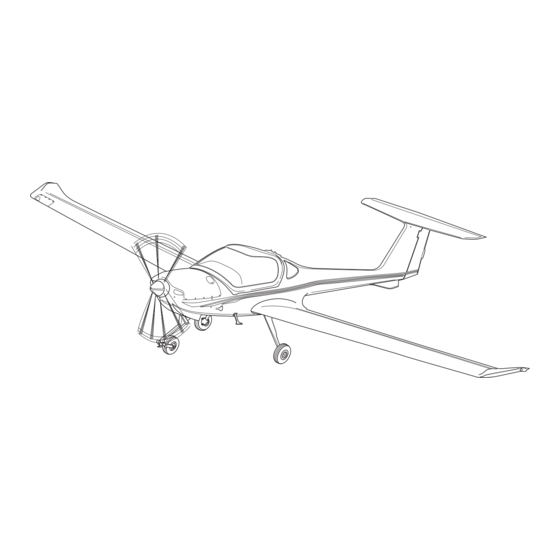
Diamond Aircraft Industries Inc., 1560 Crumlin Road, London, N5V 1S2, Ontario, Canada, make the DA20-C1 aircraft. Description The DA20-C1 aircraft is a single-engine, two seat, low-wing monoplane. It has a cantilever wing and a “T-tail” Fiber-reinforced plastic-composite makes the aircraft structure. Fiber-reinforced composite gives a very strong but light structure. - Page 78 Equipment Data The table below gives the names and address of the manufacturers who supply systems and/or equipment for the DA20-C1 aircraft. This will help you get more data on a system and/or equipment. Equipment/System Address...
- Page 79 General Description of the Aircraft DA20-C1 AMM Equipment/System Address Teledyne Battery: Teledyne Battery Products 840 West Brockton Redlands, CA 92374, USA Tel: (714) 793-3131 or 1-800-456-0070 Fax: (714) 793-5818 Tachometer: Mitchell Aircraft Products, INC 910 Sherwood Drive, Suite 20 Lake Bluff, IL 60044, USA...
- Page 80 General Description of the Aircraft DA20-C1 AMM Equipment/System Address Intercom: PS Engineering, Inc 9800 Martel Road Lenoir City, TN 37772, USA Tel: (423) 988 9800 Fax: (423) 988 6619 Vacuum Pump: Aero Accessories Inc, Filter: 1240 Springwood Ave Gibsonville NC 27249...
- Page 81 DA20-C1 AMM Airworthiness Limitations CHAPTER 04-00 AIRWORTHINESS LIMITATIONS 04-TITLE Page 1 DA201-C1 30 Oct 09 Rev 16...
- Page 82 Airworthiness Limitations DA20-C1 AMM Intentionally Left Blank 04-TITLE Page 2 DA201-C1 Rev 16 30 Oct 09...
- Page 83 DA20-C1 AMM Airworthiness Limitations TABLE OF CONTENTS Subject CH-SE-SU Page AIRWORTHINESS LIMITATIONS ........04-00-00 ..1 General.
- Page 84 Airworthiness Limitations DA20-C1 AMM Intentionally Left Blank DA201-C1 Page 2 04-TOC Rev 21 14 Jan 13...
- Page 86 Airworthiness Limitations DA20-C1 AMM Intentionally Left Blank 04-00-00 Page 2 DA201-C1 Rev 21 14 Jan 13...
- Page 87 A comprehensive airframe inspection is mandatory after 6,000 hours of flight. Paint It is mandatory to paint certain parts of the DA20-C1 aircraft white. This will help to keep the temperature of the composite structure below the structural temperature limit for the flight [55 °C (131 °F)].
- Page 88 DA20-C1 AMM Airworthiness Limitations Aircraft Life Limited Components Replace the following components at the time shown: Component Time Between Replacement 20-2720-12-00 Rudder Control Cable Short, Fwd Assembly 3000 hours or 10 years whichever comes 20-2720-11-00 Rudder Control Cable Long, Fwd Assembly first.
- Page 89 DA20-C1 AMM Airworthiness Limitations View B View A - Zone 1- Must be white, exept for registration marks, placards and minor trim - Zone 3- May be any colour. - Zone 2- May be any colour with average solar absorptivity of 0.5 or less (yellow, light green, etc.) - Zone 4- Fire resistant paint.
- Page 90 Airworthiness Limitations DA20-C1 AMM Intentionally Left Blank 04-00-00 Page 6 DA201-C1 Rev 21 14 Jan 13...
- Page 91 Time Limits and DA20-C1 AMM Maintenance Checks CHAPTER 05-00 TIME LIMITS AND MAINTENANCE CHECKS 05-TITLE Page 1 DA201-C1 30 Oct 09 Rev 16...
- Page 92 Time Limits and DA20-C1 AMM Maintenance Checks Intentionally Left Blank 05-TITLE Page 2 DA201-C1 Rev 16 30 Oct 09...
- Page 93 Time Limits and DA20-C1 AMM Maintenance Checks TABLE OF CONTENTS Subject CH-SE-SU Page TIME LIMITS AND MAINTENANCE CHECKS ......05-00-00 ..1 General.
- Page 94 Time Limits and Maintenance Checks DA20-C1 AMM TABLE OF CONTENTS Subject CH-SE-SU Page UNSCHEDULED MAINTENANCE CHECKS ....... 05-50-00 ..1 General .
-
Page 95: Time Limits And Maintenance Checks
TIME LIMITS AND MAINTENANCE CHECKS General This chapter will help you to do the maintenance of the DA20-C1 aircraft correctly. All of the usual tasks are easy to do and no special tools are necessary. Refer to AMM Chapter 04-00 and Chapter 05-00 to help you when you do maintenance and inspections. -
Page 96: Words With Special Meanings
Time Limits and Maintenance Checks DA20-C1 AMM Words with Special Meanings In this maintenance manual, the words that follow have special meanings: Adjust: To put to a specified position or condition. For example, adjust the clearance to 1 mm. Check: A technical name for a group of maintenance tasks. -
Page 97: Time Limits
Time Limits and Maintenance Checks DA20-C1 AMM TIME LIMITS General All scheduled maintenance checks have time limits. You must do the scheduled maintenance within the time limits. Some components installed in the aircraft have a fixed time between overhaul (TBO), (for example the engine). -
Page 98: Component Time Limits
Time Limits and Maintenance Checks DA20-C1 AMM Component Time Limits Overhaul the following components at the times indicated: Component Time Between Overhaul Engine, Continental Motors IO-240-B. 2000 hours. (Refer to Continental Motors Service Information Letter No SIL-98-9A). Electrical Fuel Pump, Dukes... -
Page 99: Scheduled Maintenance Checks
Time Limits and Maintenance Checks DA20-C1 AMM SCHEDULED MAINTENANCE CHECKS General Do the scheduled maintenance checks given in this chapter at the intervals stated in Chapter 05-10, Paragraph 3. Only persons authorized by national regulatory authorities of the country where the aircraft is registered may do these checks. -
Page 100: Hour Inspection
Time Limits and Maintenance Checks DA20-C1 AMM Tail All items of the fuselage, vertical stabilizer and horizontal stabilizer aft of the rear fuselage. Wings All items on the inside and outside of the left and right wings. It includes the ailerons, flaps and pitot head. - Page 101 Defect Limits for Composites Diamond Aircraft has established defect limits for inspection of composite airframe components. Refer to Chapter 51-10 for this information. Contact Diamond Aircraft if damages are determined which cannot be repaired in accordance with an approved procedures manual. 05-20-00...
- Page 102 Time Limits and Maintenance Checks DA20-C1 AMM Intentionally Left Blank 05-20-00 Page 4 DA201-C1 Rev 16 30 Oct 09...
-
Page 103: Scheduled Maintenance Checks - Maintenance Practices
DA20-C1 AMM Maintenance Practices SCHEDULED MAINTENANCE CHECKS - MAINTENANCE PRACTICES General Enter the applicable data in the blocks below: Aircraft S/N: _____________________ Registration: _______________ Engine Hours, Date: _____________________ TTSN/TSMOH: _______________ Aircraft Operating Check: _____________________ _______________ Hours: (50, 100, 200, 1000, 6000 hrs, Annual Inspection) At 25 hours time since new of an aircraft, inspect the items in the 100 hour column that DO NOT have an asterisk (*). -
Page 104: Engine Ground Test
Set the parking brake to ON. Put the chocks against the aircraft main wheels. Do an engine operational test. For the engine run procedures, refer to DA20-C1 Airplane Flight Manual. For the operational test, refer to Continental Motors IO-240 Series Engine and Overhaul... - Page 105 All items performed, the findings, as well as their correction must be recorded in accordance with an approved procedures manual. Contact Diamond Aircraft, if damages are determined that cannot be repaired in accordance with an approved procedures manual.
- Page 106 Maintenance Practices DA20-C1 AMM Interval (Flight Hours) Inspection Items, Engine 1000 Initials Cut open the used oil filter. If the filter is clogged with foreign debris, determine the source of foreign debris. Refer to Continental Motors IO-240 Series Engine and Overhaul Manual, Publication M-6.
- Page 107 DA20-C1 AMM Maintenance Practices Interval (Flight Hours) Inspection Items, Engine 1000 Initials NOTE: Refer to Continental IO-240 Series Engine and Overhaul Manual, Publication M-6 for 50 and 100 hours inspection for items 12, 13 and 15. 12. Do the 50 hour engine inspection.
- Page 108 Maintenance Practices DA20-C1 AMM Interval (Flight Hours) Inspection Items, Engine 1000 Initials 21. Examine the cabin heat system: Remove the worm drive clamp from the flexible hose at the cabin-heat selector-valve Disconnect the flexible hose to the cabin-heat selector-valve Examine the flexible hose for damage...
- Page 109 DA20-C1 AMM Maintenance Practices Interval (Flight Hours) Inspection Items, Engine 1000 Initials 32. Examine the oil cooler. Look especially for leakage and damage. Make sure that the cooling fins are not blocked. 33. Replace the air filter. (Refer to Chapter 71-60).
- Page 110 NOTE: For the fuel injection system inspection, the IDLE RPM setting for the IO-240-B engine installed in the DA20-C1 is 1000 ± 25 RPM. Refer to Continental Motors IO-240 Series Engine and Overhaul Manual, Publication M-6. 42. Do the fuel system check/adjustment.
- Page 111 DA20-C1 AMM Maintenance Practices Interval (Flight Hours) Inspection Items, Engine 1000 Initials CAUTION: FAILURE TO COMPLY WITH THE FOLLOWING MAY RESULT IN THE LOSS OF THE PROPELLER: THE HUB OF A WOODEN PROPELLER WILL SHRINK OR EXPAND TO MATCH THE AMBIENT CONDITIONS. EXCESSIVE...
- Page 112 Maintenance Practices DA20-C1 AMM Interval (Flight Hours) Inspection Items, Engine 1000 Initials 46. Check the propeller attachment bolt torques. Refer to the Chapter 61 For Sensenich propeller W69EK7-63 or W69EK7-63G (7/16" bolt attachment), refer to the Sensenich W69EK7-CF Manual For Sensenich propeller W69EK-63 (3/8" bolt...
- Page 113 Front Fuselage All items performed, the findings, as well as their correction must be recorded in accordance with an approved procedures manual. Contact Diamond Aircraft if damages are determined which cannot be repaired in accordance with an approved procedures manual.
- Page 114 Maintenance Practices DA20-C1 AMM Interval (Flight Hours) Inspection Items, Front Fuselage 1000 Initials 11. Examine the brake lining. Look especially for wear. Minimum thickness 0.12 in (3.0 mm) 12. Examine the brake disks. Look especially for wear. Minimum thickness 0.15 in (3.8 mm) 13.
- Page 115 DA20-C1 AMM Maintenance Practices Interval (Flight Hours) Inspection Items, Front Fuselage 1000 Initials 22. Visually examine the NLG fork pivot. Look especially for cracks in the radius where the fork makes contact, corrosion and wear. Any corrosion needs to be assessed, treated and/or...
- Page 116 Cockpit All items performed, the findings, as well as their correction must be recorded in accordance with an approved procedures manual. Contact Diamond Aircraft if damages are determined which cannot be repaired in accordance with an approved procedures manual. Interval (Flight Hours)
- Page 117 DA20-C1 AMM Maintenance Practices Interval (Flight Hours) Inspection Items, Cockpit 1000 Initials 12. Examine the rudder pedals. Look especially for correct attachment and function. (Refer to Chapter 27-20). 13. Examine the complete rudder control system (cables, pulleys, brackets, hardware, and surrounding structure).
- Page 118 Maintenance Practices DA20-C1 AMM Interval (Flight Hours) Inspection Items, Cockpit 1000 Initials 22. Examine the vacuum inlet filter. (Aircraft with pneumatic instrument system only) Make sure that: The filter is correctly attached The filter is clean Replace the filter at 500 hour intervals.
- Page 119 Center Fuselage, Internal All items performed, the findings, as well as their correction must be recorded in accordance with an approved procedures manual. Contact Diamond Aircraft if damages are determined which cannot be repaired in accordance with an approved procedures manual.
- Page 120 Maintenance Practices DA20-C1 AMM Interval (Flight Hours) Inspection Items, Center Fuselage, Internal 1000 Initials 10. Examine the flap control mechanism on the aft control bulkhead. Look especially for damage, corrosion, correct attachment and lock devices. 11. Examine the aileron control system on the aft control bulkhead.
- Page 121 Rear Fuselage All items performed, the findings, as well as their correction must be recorded in accordance with an approved procedures manual. Contact Diamond Aircraft if damages are determined which cannot be repaired in accordance with an approved procedures manual.
- Page 122 Tail All items performed, the findings, as well as their correction must be recorded in accordance with an approved procedures manual. Contact Diamond Aircraft if damages are determined which cannot be repaired in accordance with an approved procedures manual. Interval (Flight Hours)
- Page 123 DA20-C1 AMM Maintenance Practices Interval (Flight Hours) Inspection Items, Tail 1000 Initials 11. Examine the bottom edge of the rudder. Look especially for cracks and deformation. 12. Examine the rudder-stop reinforcement bars. Look especially for cracks and corrosion. 13. Examine the trim actuator. Look especially for correct attachment and wear.
- Page 124 Wings All items performed, the findings, as well as their correction must be recorded in accordance with an approved procedures manual. Contact Diamond Aircraft if damages are determined which cannot be repaired in accordance with an approved procedures manual. Interval (Flight Hours)
- Page 125 DA20-C1 AMM Maintenance Practices Interval (Flight Hours) Inspection Items, Wings 1000 Initials Grease the B-bolts. Refer to Chapter 12-20. Visually examine the ailerons. Look especially for damage (dents, cracks, holes and delamination). Examine the aileron hinges and control horns. Check the laminate around the hinges and the control horn fasteners for cracks, corrosion or delamination.
- Page 126 Maintenance Practices DA20-C1 AMM Interval (Flight Hours) Inspection Items, Wings 1000 Initials Examine the flap hinges and control horn. Check the laminate around the hinges and the control horn fasteners for cracks or delamination. Look especially for too much play. Play allowed: Axial: ±...
- Page 127 General All items performed, the findings, as well as their correction must be recorded in accordance with an approved procedures manual. Contact Diamond Aircraft if damages are determined which cannot be repaired in accordance with an approved procedures manual. Interval (Flight Hours)
- Page 128 13. Put the chocks against the main aircraft wheels. 14. Do the post maintenance operational test. For the engine run procedures refer to the DA20-C1 Airplane Flight Manual For the operational test refer to Continental Motors Maintenance Manual, Chapter 23 Record the data (Refer to Paragraph 7).
-
Page 129: 5.2 Maintenance Of Checklist Zones
DA20-C1 AMM Maintenance Practices 6000 Hour Inspection NOTE: All 1000 hour inspection items must be performed in addition to the 6000 hour inspection items below. Engine Ground Test Perform all inspection items described in 1000 hour interval. 5.2 Maintenance of Checklist Zones Perform all inspection items described in 1000 hour interval along with the following: A. - Page 130 Maintenance Practices DA20-C1 AMM Interval (Flight Hours) Inspection Items, Front Fuselage 6000 Initials Do a visual inspection of the NLG bushings in the T- panel on the bottom of the fuselage. - Check for the security of the bushing in the T-panel...
- Page 131 DA20-C1 AMM Maintenance Practices D. Center Fuselage, Internal Interval (Flight Hours) Inspection Items, Center Fuselage, Internal 6000 Initials Visually examine the B-bulkhead. Look for cracks and delamination, especially around fuel tank attachments. Visually examine the rudder yoke assembly, its attachment, and surrounding structure under the B- bulkhead.
- Page 132 Maintenance Practices DA20-C1 AMM Interval (Flight Hours) Inspection Items, Tail 6000 Initials Visually examine the forward mounting bracket of the horizontal stabilizer. Look especially for: - Cracks in the bond to the plate - Delamination in the rib around the fasteners Perform a visual inspection and a tap test of the rudder.
- Page 133 DA20-C1 AMM Maintenance Practices Interval (Flight Hours) Inspection Items, Wings 6000 Initials Perform a visual inspection and tap test of the wing roots (in front and behind the spar) to examine the bonding with the skins. At the lower wing, remove the tie-down ring to check for damage to the hole.
- Page 134 Maintenance Practices DA20-C1 AMM Interval (Flight Hours) Inspection Items, Wings 6000 Initials 12. Perform a visual inspection and tap test of the ailerons. - Examine the paint for chips, scratches and UV damage - Inspect the skin for delamination - Inspect for damage to the core or disbond between...
-
Page 135: Maintenance Report
DA20-C1 AMM Maintenance Practices Maintenance Report Complete a copy of the Maintenance Report after all of the applicable maintenance tasks in the Maintenance Checklist have been initialled. DA20-C1 Aircraft Serial Number: Registration Number: Check: __________________ (50 hr., 100 hr., 200 hr., 1000 hr., 6000 hr., Annual) REMARKS: The aircraft is airworthy with respect to its maintenance condition. -
Page 136: Maintenance Check Flight Report
Maintenance Practices DA20-C1 AMM Maintenance Check Flight Report NOTE: The maintenance check flight must be done in accordance with the applicable national regulations. MAINTENANCE CHECK FLIGHT DA20-C1 (See Maintenance Checklist for Applicability) Page 1 of 2 Registration: Pilot: Airdrome: Date:... - Page 137 DA20-C1 AMM Maintenance Practices MAINTENANCE CHECK FLIGHT DA20-C1 (See Maintenance Checklist for Applicability) Page 2 of 2 Findings Functional Check, Flight Behavior Taxiing behavior, take-off behavior Airspeed indicator Vertical speed indicator Compass Behavior during climb Cylinder head temperature Cabin heat/cabin air...
-
Page 138: Engine Ground Test Record
Maintenance Practices DA20-C1 AMM Engine Ground Test Record WARNING: DO NOT STAND WITHIN THE DANGER AREA OF THE PROPELLER. THE PROPELLER CAN CAUSE DEATH OR INJURY TO PERSONS. WARNING: MAKE SURE THAT THE ENGINE IS SAFE BEFORE YOU TURN THE PROPELLER. - Page 139 The Idle RPM and the ground static Max RPM specifications are different from the Continental Motors IO-240-B engine Maintenance Manual specifications. This is because of the engine to propeller installation in the DA20-C1 aircraft. Refer to Chapter 71-00 for data.
- Page 140 DO NOT SHUT THE ENGINE DOWN UNTIL THE CHT GOES BELOW 149 °C/300 °F. NOTE: For the fuel injection system inspection, the IDLE RPM setting for the IO-240-B engine installed in the DA20-C1 aircraft is 1000 ± 25 RPM. Set engine RPM to IDLE. Record IDLE RPM: ________________...
-
Page 141: Flightline Checks
DO ALL THE STEPS OF THE PRE-FLIGHT CHECK CAREFULLY. ACCIDENTS CAN OCCUR IF THE PRE-FLIGHT CHECK IS NOT DONE CORRECTLY. The schedule for the pilots pre-flight check is in the Airplane Flight Manual (AFM) for the DA20-C1 aircraft. Post Flight Check Do the post-flight check after the last flight of the day. - Page 142 Time Limits and Maintenance Checks DA20-C1 AMM Intentionally Left Blank 05-30-00 Page 2 DA201-C1 Rev 16 30 Oct 09...
-
Page 143: Hard Landing Check
Time Limits and Maintenance Checks DA20-C1 AMM UNSCHEDULED MAINTENANCE CHECKS General Unscheduled maintenance checks are necessary after any incident that could cause damage to the aircraft. Hard Landing Check Figure 1 shows the hard landing check areas. You must do a hard landing check when the pilot makes a report of a hard landing. - Page 144 Time Limits and Maintenance Checks DA20-C1 AMM Maintenance Work Key Items/References - Measure the maximum gap between If the gap is less or equal to 0.12 in (3mm) the rod and the strut. examine the strut for corrosion and cracks particularly in the area of the maximum gap.
-
Page 145: Propeller Strike
Time Limits and Maintenance Checks DA20-C1 AMM Maintenance Work Key Items/References Examine the engine mount points on the firewall. Examine the propeller. Look especially to see if the propeller touched the ground. Examine instrument panel shock mounts Hard landings can cause instrument glass for damage. -
Page 146: Engine Fire
Time Limits and Maintenance Checks DA20-C1 AMM CAUTION: OVER PRIMING CAN CAUSE A FLOODED INTAKE RESULTING IN A "HYDRAULIC LOCK" EVENT AND SUBSEQUENT ENGINE MALFUNCTION OR FAILURE. IF YOU OVER PRIME, OR FLOOD YOUR ENGINE, MAKE CERTAIN THAT ALL FUEL HAS DRAINED FROM THE INTAKE MANIFOLD AND/OR CYLINDER PRIOR TO ATTEMPTING ENGINE STARTING. - Page 147 Refer to the Continental Motors IO-240 engine fire. Series Engine and Overhaul Manual, Publication M-6. - Repair the defect. Do a test of the engine. Refer to the DA20-C1 Airplane Flight Manual. 05-50-00 Page 5 DA201-C1 14 Jan 13 Rev 21...
- Page 148 Time Limits and Maintenance Checks DA20-C1 AMM Overspeed Flap Extension If the flaps are extended above V or left extended above V an inspection of the flap system including the main bell crank must be completed. Maintenance Work Key Items/References...
- Page 149 Time Limits and Maintenance Checks DA20-C1 AMM Spar Bridge Inner Mount Main Gear Strut Outer Mount Attachment to Engine Mount Journal Assembly Shock Absorber Assembly Axle Attachment Nose Leg Brake Disk Bearings in Fuselage Wheel and Tire Pivot Assembly Figure 1 - Hard Landing Check Areas...
- Page 150 Time Limits and Maintenance Checks DA20-C1 AMM Intentionally Left Blank Page 8 05-50-00 DA201-C1 30 May 14 Rev 22...
- Page 151 DA20-C1 AMM Dimensions and Areas CHAPTER 06-00 DIMENSIONS AND AREAS 06-TITLE Page 1 DA201-C1 30 Oct 09 Rev 16...
- Page 152 DA20-C1 AMM Dimensions and Areas Intentionally Left Blank 06-TITLE Page 2 DA201-C1 Rev 16 30 Oct 09...
- Page 153 DA20-C1 AMM Dimensions and Areas TABLE OF CONTENTS Subject CH-SE-SU Page DIMENSIONS AND AREAS ..........06-00-00 ..1 General.
- Page 154 Dimensions and Areas DA20-C1 AMM Intentionally Left Blank DA201-C1 Page 2 06-TOC Rev 21 14 Jan 13...
-
Page 155: Dimensions And Areas
DA20-C1 AMM Dimensions and Areas DIMENSIONS AND AREAS General The DA 20-C1 aircraft uses the Imperial measurement for dimensions and areas. System International (SI) dimensions are also given in brackets. For example: Wing span 35.4 ft. (10.78 m). Unit Conversions... - Page 156 Dimensions and Areas DA20-C1 AMM 10890 mm (35 ft 9 in) 1860 mm (6 ft 1 in) 7240 mm (23 ft 9 in) 1600 mm 2160 mm (5 ft 3 in) (7 ft 1 in) Figure 1 - Overall Dimensions...
-
Page 157: Dimensions
DA20-C1 AMM Dimensions and Areas Dimensions DA20-C1 Dimensions Overall Dimensions Wing Span 35 ft 9 in (10.89 m) Length 23 ft 9 in (7.24 m) Height (Nominal) 7 ft 1 in (2.16 m) Wing Airfoil Wortmann FX63-137/20-HOAC Wing Area 125 ft (11.6 m... - Page 158 Dimensions and Areas DA20-C1 AMM Figure 2 - Control Surface Deflections DA201-C1 Page 4 06-00-00 Rev 21 14 Jan 13...
- Page 159 DA20-C1 AMM Dimensions and Areas Diamond Aircraft DA20-C1 S/N: __________________ Date: _________________ INSP.: _______________ ITEM DEFLECTION WEIGHT STATIC MOMENTS BEFORE BALANCING AFTER BALANCING MOMENT TRAILING EDGE BALANCE LIMITS ACTUAL LIMITS ACTUAL WEIGHT LIMITS ACTUAL WEIGHT LIMITS ACTUAL (degrees) (degrees) (kg)
- Page 160 DA20-C1 AMM Dimensions and Areas Diamond Aircraft DA20-C1 S/N: __________________ Date: _________________ INSP.: _______________ ITEM LIMITS ACTUAL ITEM LIMITS ACTUAL HORIZONTAL FLAP PRELOAD LEFT 3.0 to 5.0 -4° ± 0.5° STABILIZER (kg) RIGHT (kg) degrees INCIDENCE MAIN LANDING 0° to 4°...
-
Page 161: Adjustment Values
Dimensions and Areas Adjustment Values The measurements of the DA20-C1 aircraft are recorded on an Adjustment Report at the factory when the aircraft is built. See Figures 2 and 3. This Report becomes part of the aircraft records. When you measure the dimensions, use the Adjustment Report as a reference for deviations. - Page 162 DA20-C1 AMM Dimensions and Areas Intentionally Left Blank 06-00-00 Page 8 DA201-C1 Rev 21 14 Jan 13...
- Page 163 DA20-C1 AMM Lifting and Shoring CHAPTER 07-00 LIFTING AND SHORING 07-TITLE Page 1 DA201-C1 30 Oct 09 Rev 16...
- Page 164 DA20-C1 AMM Lifting and Shoring Intentionally Left Blank 07-TITLE Page 2 DA201-C1 Rev 16 30 Oct 09...
- Page 165 DA20-C1 AMM Lifting and Shoring TABLE OF CONTENTS Subject CH-SE-SU Page LIFTING AND SHORING ..........07-00-00 ..1 General.
- Page 166 Lifting and Shoring DA20-C1 AMM Intentionally Left Blank DA201-C1 Page 2 07-TOC Rev 21 14 Jan 13...
- Page 167 LIFTING AND SHORING General The DA20-C1 aircraft is a light airplane. It has no hoisting points. Use belts to lift the airplane. You can use your hands to lift the wings and the horizontal stabilizer. The DA20-C1 aircraft has 2 jacking points and a tail support. For maintenance lift the fuselage with the 2 hydraulic jacks.
- Page 168 DA20-C1 AMM Lifting and Shoring Intentionally Left Blank 07-00-00 Page 2 DA201-C1 Rev 21 14 Jan 13...
- Page 169 DA20-C1 AMM JACKING General The DA20-C1 aircraft has two jacking points. They are located under the fuselage at the root ribs. To support the rear fuselage a trestle with a former is positioned in front of the tail skid. WARNING: IF THE WIND SPEED IS MORE THAN 10 KM/HR (6 KNOTS), DO NOT LIFT THE AIRCRAFT ON JACKS IN THE OPEN.
- Page 170 DA20-C1 AMM Lifting and Shoring Detail Steps/Work Items Key Items/References Remove the chocks and release the parking brake. Extend the jacks until the wheels are clear of the Operate the jacks together to keep the ground. aircraft level. Tie the tail down with the hold down strap.
- Page 171 Lifting and Shoring DA20-C1 AMM Figure 1 - Lifting the Aircraft on Jacks 07-10-00 Page 3 DA201-C1 30 Oct 09 Rev 16...
- Page 172 Lifting and Shoring DA20-C1 AMM Intentionally Left Blank 07-10-00 Page 4 DA201-C1 Rev 16 30 Oct 09...
- Page 173 DA20-C1 AMM Leveling and Weighing CHAPTER 08-00 LEVELING AND WEIGHING 08-TITLE Page 1 DA201-C1 30 Oct 09 Rev 16...
- Page 174 Leveling and Weighing DA20-C1 AMM Intentionally Left Blank 08-TITLE Page 2 DA201-C1 Rev 16 30 Oct 09...
- Page 175 DA20-C1 AMM Leveling and Weighing TABLE OF CONTENTS Subject CH-SE-SU Page LEVELING AND WEIGHING ......... . . 08-00-00 ..1 General.
- Page 176 Leveling and Weighing DA20-C1 AMM Intentionally Left Blank DA201-C1 Page 2 08-TOC Rev 21 14 Jan 13...
- Page 177 Leveling and Weighing DA20-C1 AMM LEVELING AND WEIGHING General This chapter describes how to weigh and level the aircraft. Use the procedures in Chapter 08-10 to weigh the aircraft and to calculate the aircraft moment. Use the procedures in Chapter 08-20 to level the aircraft.
- Page 178 Leveling and Weighing DA20-C1 AMM Intentionally Left Blank 08-00-00 Page 2 DA201-C1 Rev 21 14 Jan 13...
- Page 179 Leveling and Weighing DA20-C1 AMM WEIGHING General Only operate the aircraft within the permitted range of weight and center of gravity limits. This will give good flight performance and good handling qualities. It is also necessary for safety. If you make any changes to the aircraft that will alter the weight (or the center of gravity), then you must calculate the new weight of the aircraft and its center of gravity.
- Page 180 The scales under the main wheels must be the same. NOTE: Make sure that the aircraft is at pre-weighing conditions. Refer to DA20-C1 Airplane Flight Manual (AFM), Chapter 06. NOTE: Make sure that each wheel is in the center of the weighing scale. If the wheel is on the side of the scale the data can be wrong.
- Page 181 Leveling and Weighing DA20-C1 AMM Detail Steps/Work Items Key Items/References With the aircraft correctly positioned, do the Refer to Figure 3. following: - Drop a plumb line from the leading edge of each wing at the root rib to the floor.
- Page 182 Leveling and Weighing DA20-C1 AMM Figure 1: Level The Aircraft Laterally For Weighing Figure 2: Level The Aircraft Longitudinally For Weighing Page 4 08-10-00 DA201-C1 01 Nov 10 Rev 17...
- Page 183 Leveling and Weighing DA20-C1 AMM 2 R H 2 L H 2 L H 2 R H Legend: = Arm - Datum to center line nose wheel = Arm - Datum to C/L main wheels (LH and RH) = Net weight - Nose wheel...
- Page 184 Leveling and Weighing DA20-C1 AMM Model: DA20-C1 Serial Number:___________ Registration_____________ Data with reference to the Type Certificate Data Sheet and the Airplane Flight Manual. Reference Datum: Leading edge of wing at root rib. Horizontal reference line: Wedge 1000:55.84, 2000mm (78.7 in) aft of the step in the fuselage at the canopy edge.
- Page 185 Leveling and Weighing DA20-C1 AMM LEVELING General The following procedures describe how to make the aircraft level. Refer to Chapter 07-10 for lifting the aircraft with jacks. You can make the aircraft level with jacks. Or you can make the aircraft level by changing the tire pressures.
- Page 186 DA20-C1 AMM Leveling and Weighing Detail Steps/Work Items Key Items/References Align the aircraft longitudinally. - Put the 1000:55.84 wedge on the fuselage. - Place the spirit level on the wedge. - Lift or lower the rear fuselage with the tail trestle to make the fuselage level.
- Page 187 Leveling and Weighing DA20-C1 AMM Figure 1: Level The Aircraft Laterally Figure 2 - Level the Aircraft Longitudinally 08-20-00 Page 3 DA201-C1 30 Oct 09 Rev 16...
- Page 188 Leveling and Weighing DA20-C1 AMM Intentionally Left Blank 08-20-00 Page 4 DA201-C1 Rev 16 30 Oct 09...
- Page 189 Towing and Taxiing DA20-C1 AMM CHAPTER 09-00 TOWING AND TAXIING DA201-C1 Page 1 09-TITLE Rev 16 30 Oct 09...
- Page 190 Towing and Taxiing DA20-C1 AMM Intentionally Left Blank 09-TITLE Page 2 DA201-C1 Rev 16 30 Oct 09...
- Page 191 DA20-C1 AMM Towing and Taxiing TABLE OF CONTENTS Subject CH-SE-SU Page Towing and Taxiing..........09-00-00 ..1 General.
- Page 192 Towing and Taxiing DA20-C1 AMM Intentionally Left Blank DA201-C1 Page 2 09-TOC Rev 21 14 Jan 13...
- Page 193 DA20-C1 AMM Towing and Taxiing TOWING AND TAXIING General You can move the aircraft on the ground with the tow bar, or by taxiing the aircraft. WARNING: YOU MUST NOT TAXI THE AIRCRAFT UNLESS YOU HAVE BEEN TRAINED TO TAXI.
- Page 194 Towing and Taxiing DA20-C1 AMM Intentionally Left Blank Page 2 09-00-00 DA201-C1 14 Jan 13 Rev 21...
- Page 195 Tools and Equipment Use the DA20-C1 aircraft tow bar to move the aircraft. The tow bar is part of the aircraft standard equipment. One person can move the aircraft on a flat surface. Use the sliding strap to close the arms of the tow bar and use your hands to open the arms of the tow bar.
- Page 196 Towing and Taxiing DA20-C1 AMM Towing Procedure WARNING: MAKE SURE THAT THE PINS OF THE TOW BAR ARE CORRECTLY ENGAGED IN THE NOSE WHEEL STRUT. IF THE PINS ARE NOT CORRECTLY ENGAGED, THE TOW BAR CAN DETACH. THE AIRCRAFT CAN CAUSE INJURY TO PERSONS.
- Page 197 Towing and Taxiing DA20-C1 AMM Detail Steps/Work Items Key Items/References CAUTION: DO NOT PUSH OR PULL THE CONTROL SURFACES WHEN TOWING. YOU CAN CAUSE DAMAGE TO THE CONTROL SURFACES. Move the aircraft to its new position. Put wheel chocks in front and behind the main wheels.
- Page 198 NEVER TOW THE AIRCRAFT IF THE WHEELS ARE BLOCKED BY SNOW OR MUD. YOU CAN DAMAGE THE LANDING GEAR. You can also move the aircraft without using a tow bar. You can push the DA20-C1 aircraft at the wing tip and at the wing-fuselage connection.
- Page 199 THIS SECTION GIVES GENERAL DATA ON TAXIING ONLY. YOU MUST USE THE DA20-C1 AIRPLANE FLIGHT MANUAL WHEN YOU TAXI THE AIRCRAFT. When you taxi the DA20-C1 aircraft, use the toe operated brakes to steer the aircraft. To make the aircraft turn, operate the left or the right toe brake.
- Page 200 MUST NOT TOUCH THE GROUND. LOOSE STONES AND GRAVEL CAN DAMAGE THE PROPELLER. Taxi the aircraft to its new position. Shut down the engine. Refer to DA20-C1 Airplane Flight Manual. Park the aircraft. If necessary, moor the Refer to Chapter 10-00. aircraft.
- Page 201 Parking, Mooring, Storage DA20-C1 AMM and Return to Service CHAPTER 10-00 PARKING, MOORING, STORAGE AND RETURN TO SERVICE 10-TITLE Page 1 DA201-C1 30 Oct 09 Rev 16...
- Page 202 Parking, Mooring, Storage and Return to Service DA20-C1 AMM Intentionally Left Blank 10-TITLE Page 2 DA201-C1 Rev 16 30 Oct 09...
-
Page 203: Parking, Mooring, Storage And Return To Service
PARKING, MOORING, STORAGE AND RETURN TO SERVICE General Always park or moor the DA20-C1 aircraft when it is not in use. Use the procedures in Chapter 10-10 for parking the aircraft. Use the procedure in Chapter 10-20 to moor the aircraft. If the aircraft is parked over night, we recommend that you moor the aircraft. - Page 204 Parking, Mooring, Storage DA20-C1 AMM and Return to Service Intentionally Left Blank 10-00-00 Page 2 DA201-C1 14 Jan 13 Rev 21...
- Page 205 Parking, Mooring, Storage DA20-C1 AMM and Return to Service TABLE OF CONTENTS Subject CH-SE-SU Page PARKING, MOORING, STORAGE AND RETURN TO SERVICE....10-00-00 ..1 General.
- Page 206 Parking, Mooring, Storage and Return to Service DA20-C1 AMM Intentionally Left Blank DA201-C1 Page 2 10-TOC Rev 21 14 Jan 13...
- Page 207 Parking, Mooring, Storage DA20-C1 AMM and Return to Service PARKING/STORAGE General Use these procedures to protect the aircraft when it is parked. Use the short-term parking procedure when the aircraft will be parked for less than 5 days. Use the long term parking procedure when the aircraft will be parked for 5 to 30 days.
- Page 208 Parking, Mooring, Storage and Return to Service DA20-C1 AMM Detail Steps/Work Items Key Items/References Set the parking brake OFF. Push the knob fully forward. Set the controls to neutral. Install the control lock. Set the flaps to CRUISE. Fully up.
- Page 209 Parking, Mooring, Storage DA20-C1 AMM and Return to Service Preparation Detail Steps/Work Items Key Items/References If the aircraft will be parked between 30 and 90 Refer to Continental Motors IO-240 Series days, do the procedure for Temporary Storage Engine Maintenance and Overhaul Manual for the engine.
- Page 210 Parking, Mooring, Storage DA20-C1 AMM and Return to Service Intentionally Left Blank 10-10-00 Page 4 DA201-C1 Rev 20 12 Jun 12...
- Page 211 Parking, Mooring, Storage DA20-C1 AMM and Return to Service MOORING General If the aircraft must be left outside for a long time, you must moor it. Strong winds or gusts can cause damage to an aircraft that is not moored.
- Page 212 Parking, Mooring, Storage and Return to Service DA20-C1 AMM Figure 1 - Location of the Mooring Points on the Aircraft 10-20-00 DA201-C1 Page 2 30 Oct 09 Rev 16...
- Page 213 Parking, Mooring, Storage DA20-C1 AMM and Return to Service RETURN TO SERVICE General Do this procedure when the aircraft has been parked (or stored) for more than 5 days. Return to Service Procedure Detail Steps/Work Items Key Items/References If the engine was preserved/stored in...
- Page 214 Parking, Mooring, Storage and Return to Service DA20-C1 AMM Intentionally Left Blank 10-30-00 Page 2 DA201-C1 Rev 16 30 Oct 09...
- Page 215 Placards and Markings DA20-C1 AMM CHAPTER 11-00 PLACARDS AND MARKINGS 11-TITLE DA201-C1 Page 1 30 Oct 09 Rev 16...
- Page 216 Placards and Markings DA20-C1 AMM Intentionally Left Blank 11-TITLE Page 2 DA201-C1 30 Oct 09 Rev 16...
- Page 217 DA20-C1 AMM Placards and Markings TABLE OF CONTENTS Subject CH-SE-SU Page PLACARDS AND MARKINGS......... . 11-00-00 ..1 General .
- Page 218 Placards and Markings DA20-C1 AMM Intentionally Left Blank 11-TOC DA201-C1 Page 2 Rev 21 14 Jan 13...
- Page 219 DA20-C1 AMM Placards and Markings PLACARDS AND MARKINGS General Placards are used for identification and indication. They show the function, operation and operating limitations of systems and equipment. This chapter shows you the location of the exterior placards and markings and the location of the interior placards.
- Page 220 Placards and Markings DA20-C1 AMM Intentionally Left Blank DA201-C1 Page 2 11-00-00 14 Jan 13 Rev 21...
-
Page 221: Exterior Placards And Markings
DA20-C1 AMM Placards and Markings EXTERIOR PLACARDS AND MARKINGS General The DA20-C1 aircraft has the following exterior placards. TO LIFT CANOPY OPEN BOTH SIDES OPEN TO OPEN UNLATCH BOTH SIDES NOTE: One of the Placards is CANOPY: AND LIFT UP CANOPY... - Page 222 Placards and Markings DA20-C1 AMM STEP BELOW EMERGENCY LOCATOR TRANSMITTER INSTALLED HERE CAUTION USE ONLY AVIATION ICIL’ HERE GRADE OIL! EMPLACEMENT DE LA RADIOBALISE 6.0 US Qts. DE DETRESSE 5.68 I SAE 20W-50 OR ACCORDING TO FLIGHT MANUAL INLET AND OUTLET BAFFLES MUST BE REMOVED ABOVE 12.5 C/54.5 F...
- Page 223 DA20-C1 AMM Placards and Markings NOTE: The Placards and Markings shown are on the lower surfaces of the airplane. Figure 2 - Exterior Placards - Lower Surfaces (Sheet 1 of 2) 11-20-00 Page 3 DA201-C1 30 May 14 Rev 22...
- Page 224 Placards and Markings DA20-C1 AMM NOTE: The Placards and Markings shown are on the lower surfaces of the airplane. Figure 2 - Exterior Placards - Lower Surfaces (Sheet 2 of 2) 11-20-00 DA201-C1 Page 4 30 May 14 Rev 22...
-
Page 225: Interior Placards And Markings
DA20-C1 AMM Placards and Markings INTERIOR PLACARDS AND MARKINGS General Figures 1 through 8 show the interior placards and markings. Figure 1 - Placards on the Instrument Panel (Up to S/N 0149) (Sheet 1 of 2) 11-30-00 Page 1 DA201-C1... - Page 226 DA20-C1 AMM Placards and Markings TRIM NOSE UP M800 CHRONOMETER NEUTRAL ° F 12:45 NOSE DOWN 360 420 This airplane is classified as a very light SELECT CONTROL Cylinder Head airplane approved for VFR only, in non-icing x100°F T emp.
- Page 227 DA20-C1 AMM Placards and Markings Figure 2 - Placards on the Instrument Panel (S/N 0150 and subs) (Sheet 1 of 2) 11-30-00 Page 3 DA201-C1 30 May 14 Rev 22...
- Page 228 DA20-C1 AMM Placards and Markings 14VDC ACCESSORY PWR. GROUND OPS. ONLY 2A MAX AUTOPILOT MAX. OPERATING SPEED 148 KIAS A/P OPS PROHIBITED FOR T/O & LDG MAX FLAP T/O (15 ) WITH A/P ON NOTE: Only installed if Auto Pilot GEN/BAT (T/O) 100 KTS.
- Page 229 DA20-C1 AMM Placards and Markings TRIM NOSE UP M800 CHRONOMETER NEUTRAL ° F 12:45 NOSE DOWN 360 420 This airplane is classified as a very light SELECT CONTROL Cylinder Head airplane approved for VFR only, in non-icing x100°F Temp. conditions.
- Page 230 DA20-C1 AMM Placards and Markings Figure 4 - Placards on the Reversed Instrument Panel (Sheet 1 of 2) 11-30-00 DA201-C1 Page 6 30 May 14 Rev 22...
- Page 231 DA20-C1 AMM Placards and Markings Figure 4 - Placards on the Reversed Instrument Panel (Sheet 2 of 2) 11-30-00 Page 7 DA201-C1 30 May 14 Rev 22...
- Page 232 DA20-C1 AMM Placards and Markings ENGINE FUEL PRESS TACH. START OIL PRESS OIL TEMP SYSTEM TURN PITOT FUEL FUEL/QTY. FLAPS TRIM HEAT & PUMP O.A.T. SLIP SYSTEM LIGHTS STROBE INST. HORIZON LANDING TAXI/MAP POSITION AVIONICS MASTER COM1 GPS/NAV MASTER CONTROL...
- Page 233 DA20-C1 AMM Placards and Markings CAUTION! This airplane is classified as a very light airplane GROUND approved for VFR only, in non-icing conditions. All aerobatic maneuvers, except for intentional TRIM ENGINE OPERATION. spinning which is permitted with flaps UP only are...
- Page 234 DA20-C1 AMM Placards and Markings Figure 7 - Placards on the Instrument Panel with Garmin G500 Display (Sheet 1 of 2) 11-30-00 DA201-C1 Page 10 30 May 14 Rev 22...
- Page 235 DA20-C1 AMM Placards and Markings Figure 7 - Placards on the Instrument Panel with Garmin G500 Display (Sheet 2 of 2) 11-30-00 Page 11 DA201-C1 30 May 14 Rev 22...
- Page 236 DA20-C1 AMM Placards and Markings Figure 8 - Placards on the Instrument Panel with Garmin G500 Display, UMA engine instruments and Garmin GTN650/GTR225 installed. 11-30-00 DA201-C1 Page 12 30 May 14 Rev 22...
- Page 237 DA20-C1 AMM Placards and Markings Figure 9- General Interior Placards and Markings (Sheet 1 of 3) 11-30-00 Page 13 DA201-C1 30 May 14 Rev 22...
- Page 238 DA20-C1 AMM Placards and Markings Figure 9- General Interior Placards and Markings (Sheet 2 of 3) 11-30-00 DA201-C1 Page 14 30 May 14 Rev 22...
- Page 239 DA20-C1 AMM Placards and Markings (Leather Seats) (Sheepskin Seats) Hydraulic Fluid 4 MIL-H-5606 Hydraulic Fluid MIL-H-5606 ALTERNATE FUEL POWER OFF FULL RICH MIXTURE OFF FULL RICH OFF FULL RICH OFF FULL RICH Figure 9- General Interior Placards and Markings (Sheet 3 of 3)
- Page 240 Placards and Markings DA20-C1 AMM Intentionally Left Blank 11-30-00 Page 16 DA201-C1 Rev 22 30 May 14...
- Page 241 DA20-C1 AMM Servicing CHAPTER 12-00 SERVICING 12-TITLE Page 1 DA201-C1 30 Oct 09 Rev 16...
- Page 242 Servicing DA20-C1 AMM Intentionally Left Blank Page 2 DA201-C1 12-TITLE 30 Oct 09 Rev 16...
- Page 243 DA20-C1 AMM Servicing TABLE OF CONTENTS Subject CH-SE-SU Page SERVICING ............12-00-00 ..1 General.
- Page 244 Servicing DA20-C1 AMM Intentionally Left Blank DA201-C1 Page 2 12-TOC Rev 21 14 Jan 13...
- Page 245 DA20-C1 AMM Servicing SERVICING General This Chapter gives the following servicing tasks that apply to the whole aircraft: Section 12-10. Replenishing procedures for fluid systems Section 12-20. Lubrication data Section 12-30. Cleaning and snow and ice removal. The procedures for the preventive and corrective maintenance of systems are given in the related Chapter of this manual.
- Page 246 Servicing DA20-C1 AMM Intentionally Left Blank DA201-C1 Page 2 12-00-00 14 Jan 13 Rev 21...
- Page 247 Fuel System A tank in the fuselage holds the fuel for the DA20-C1 aircraft. The tank can hold 24.5 US gal (93 liters) of fuel. A fuel tank with a capacity of 20 US gal (76 liters) may be installed in place of the standard tank as an option.
- Page 248 Servicing DA20-C1 AMM Detail Steps/Work Items Key Items/References Replace the fuel filler cap. Make sure that the fuel filler cap is locked. Remove the ground cable from the aircraft. At the refueling ground connection. Remove the ground cable from the refueling vehicle.
- Page 249 Servicing DA20-C1 AMM Figure 1 - Replenishing Points 12-10-00 Page 3 DA201-C1 30 Oct 09 Rev 16...
- Page 250 ENGINE MALFUNCTION OR FAILURE. The engine installed in the DA20-C1 aircraft has a wet-sump oil system. The oil sump can hold 6 US quarts (5.68 liters). See Table 1 for approved oils and Figure 2 for selection of viscosity according to the various climatic conditions.
- Page 251 Servicing DA20-C1 AMM Table 1 - Engine Oil All seasonal weight: All temperatures SAE 5W-50 Below 40 ºF (4.5 ºC) Ambient air, sea level SAE 30 or Multi Viscosity Above 40 ºF (4.5 ºC) Ambient air, sea level SAE 50 or Multi Viscosity The viscosity should be selected according to the various climatic conditions as shown in Figure 1.
- Page 252 Install the filler cap. Tires The DA20-C1 has the following tires: Main tire: 5.00 x 5 - pressure 33 psi (2.3 bar) Nose tire: 5.00 x 4 - pressure 26 psi (1.8 bar). Examine the Tires and Measure the Pressure...
-
Page 253: Scheduled Servicing
DA20-C1 AMM Servicing SCHEDULED SERVICING General This chapter gives the lubrication data. It describes where components are located and gives a list of approved lubricants. It also gives the components which MUST NOT be lubricated. Most systems and components have maintenance-free bearings. These can be sealed ball/roller bearings or Teflon bushings. - Page 254 Servicing DA20-C1 AMM Lubrication Schedule Table 2 shows the lubrication schedule. Clean each lubrication point before lubrication. See Figure 1 (Sheets 1 and 2) for the location of the lubrication points listed on the left side of the table. Refer to Table 3 for the type of lubricant that is required for each item.
- Page 255 DA20-C1 AMM Servicing Table 2 - Lubrication Schedule Location Type of Lubricant Interval (See Table 3) See Figure 1 and 2 (Hours) see Notes (1), (2) Cable eyes on rudder • Rudder hinge bushing • Flap, Aileron, Elevator hinge bearings •...
- Page 256 Servicing DA20-C1 AMM Table 3 - Lubricant Specifications Specification Product Manufacturer TYPE 1 MIL-G-81322 AeroShell Grease 22 Shell Canada Products Limited P O Box 100 Station M Calgary, Alberta, T2P 2H5 Canada Shell Oil Co P O Box 2463, One Shell Plaza...
- Page 257 DA20-C1 AMM Servicing Table 3 - Lubricant Specifications TYPE 4 VV-P-236 (petrolatum) Royco 1 Royal Lubricants Co Inc. River Road East Hanover, NJ 07936, USA DC 4 Dow Corning S Saginaw Rd Midland, MI 48641, USA TYPE 5 MIL-C-16173 (grade 2)
- Page 258 Servicing DA20-C1 AMM NOTE: On some aircraft the lubrication hole may be on the back side. Figure 1 - Lubrication Points - Sheet 1 of 2 12-20-00 DA201-C1 Page 6 12 Jun 12 Rev 20...
- Page 259 DA20-C1 AMM Servicing Figure 1 - Lubrication Points - Sheet 2 of 2 12-20-00 Page 7 DA201-C1 30 Oct 09 Rev 16...
- Page 260 Servicing DA20-C1 AMM Intentionally Left Blank 12-20-00 Page 8 DA201-C1 Rev 16 30 Oct 09...
-
Page 261: Unscheduled Servicing
This chapter describes how to clean the aircraft and how to remove snow and ice from the aircraft. Exterior Cleaning The outer surfaces of the DA20-C1 aircraft must be kept clean to keep the good performance characteristics of the aircraft. The leading edges of the wings are specially important. - Page 262 Servicing DA20-C1 AMM Protect all electrical components and engine intakes with polythene bags or other means. Obey the cleaning agent manufacturers instructions. Protect the vacuum pump and it's main components from contamination. Make sure that the vacuum pump fittings are not loose. Refer to the manufacturers Maintenance Instruction Manual for more data.
- Page 263 DA20-C1 AMM Standard Practices - Airframe CHAPTER 20-00 STANDARD PRACTICES AIRFRAME Page 1 DA201-C1 20-TITLE 30 Oct 09 Rev 16...
- Page 264 Standard Practices - Airframe DA20-C1 AMM Intentionally Left Blank Page 2 20-TITLE DA201-C1 30 Oct 09 Rev 16...
- Page 265 DA20-C1 AMM Standard Practices - Airframe TABLE OF CONTENTS Subject CH-SE-SU Page STANDARD PRACTICES - AIRFRAME ........20-00-00 ..1 General.
- Page 266 Standard Practices - Airframe DA20-C1 AMM Intentionally Left Blank DA201-C1 Page 2 20-TOC Rev 21 14 Jan 13...
-
Page 267: Standard Practices - Airframe
REDUCES WITH USE. Bolt and Nut Types Used in the Aircraft The DA20-C1 uses 2 types of standard bolt: AN3 through AN20 and DIN 985 specifications. You can identify the bolt type by the marking on the head and the surface treatment. -
Page 268: Standard Torque Values
DA20-C1 AMM Standard Practices - Airframe Standard Torque Values These tables show the maximum permissible torque values for bolts and nuts to AN and DIN specifications. AN Fine Thread Series Bolt Size Torque (lbf-ft) Torque (Nm) 10 - 32 1/4 - 28 5/16 - 24 10.0... -
Page 269: Special Torque Values
DA20-C1 AMM Standard Practices - Airframe DIN Specifications Metric Thread Torque (lbf-ft) Torque (Nm) 11.8 16.0 23.6 32.0 44.4 60.0 Use the above torque values for all bolts/nuts/screws which meet the specifications unless they are in the list of special torque values below. - Page 270 DA20-C1 AMM Standard Practices - Airframe Part Torque (lbf-ft) Torque (Nm) Brake flexible hoses 3.3 - 5 4.5 - 6.8 B-Bolt nut in root rib 14.8 20.0 Safety belt attachment in center console Loose fit, NO torque M10 bolt attaching generator to bottom mounting 26.3...
- Page 271 DA20-C1 AMM Standard Practices - Airframe Graph 1 - Nm - ft.lb Page 5 DA201-C1 20-00-00 14 Jan 13 Rev 21...
- Page 272 DA20-C1 AMM Standard Practices - Airframe Graph 2 - Nm - in.lb 20-00-00 Page 6 DA201-C1 14 Jan 13 Rev 21...
- Page 273 Air Conditioning DA20-C1 AMM CHAPTER 21-00 AIR CONDITIONING DA201-C1 21-TITLE Page 1 30 Oct 09 Rev 16...
- Page 274 Air Conditioning DA20-C1 AMM Intentionally Left Blank Page 2 DA201-C1 21-TITLE 30 Oct 09 Rev 16...
- Page 275 DA20-C1 AMM Air Conditioning TABLE OF CONTENTS Subject CH-SE-SU Page HEATING AND VENTILATION ......... 21-00-00 ..1 General.
- Page 276 Air Conditioning DA20-C1 AMM Intentionally Left Blank DA201-C1 Page 2 21-TOC Rev 21 14 Jan 13...
-
Page 277: Heating And Ventilation
HEATING AND VENTILATION General The DA20-C1 aircraft has separate systems to supply hot air and cold air. The hot air system can supply air from ambient temperature to warm. The system supplies the footwells or the windscreen. The cold air system can supply ambient air to adjustable vents at each side of the instrument panel. - Page 278 Air Conditioning DA20-C1 AMM The CABIN HEAT control lever moves the flap in the heat control valve. In the OFF position (fully forward) no hot air can flow into the cockpit. Move the lever aft (towards the ON position) to let gradually more hot air flow into the cabin.
- Page 279 DA20-C1 AMM Air Conditioning Figure 1 - Heating and Ventilation Schematic Diagram DA201-C1 21-00-00 Page 3 14 Jan 13 Rev 21...
- Page 280 Air Conditioning DA20-C1 AMM Intentionally Left Blank Page 4 DA201-C1 21-00-00 14 Jan 13 Rev 21...
-
Page 281: Heating And Ventilation - Troubleshooting
Troubleshooting DA20-C1 AMM HEATING AND VENTILATION - TROUBLESHOOTING General This table explains how to troubleshoot the air conditioning system. If you find the trouble in column 1, do the repair given in column 3. TROUBLE POSSIBLE CAUSE REPAIR Burning smell in the cockpit. - Page 282 Troubleshooting DA20-C1 AMM Intentionally Left Blank 21-00-00 Page 102 DA201-C1 30 Oct 09 Rev 16...
-
Page 283: Heating And Ventilation - Maintenance Practices
Maintenance Practices DA20-C1 AMM HEATING AND VENTILATION - MAINTENANCE PRACTICES General This chapter describes about the Maintenance Practices for the distribution and heating systems. It also describes how to remove/install and adjust components. Remove/Install the Heat Control Valve Remove the Heat Control Valve... -
Page 284: Test/Adjust The Heat Control Valve
Maintenance Practices DA20-C1 AMM Detail Steps/Work Items Key Items/References Set the flap in the heat control valve to fully close the hole in the firewall. Tighten the screw in the end fitting on the flap lever to hold the inner cable. -
Page 285: Remove/Install The Distribution Box
Maintenance Practices DA20-C1 AMM Remove/Install the Distribution Box Remove the Distribution Box. Detail Steps/Work Items Key Items/References WARNING: DO NOT STAND WITHIN THE DANGER AREA OF THE PROPELLER. IF THE ENGINE STARTS, THE PROPELLER CAN CAUSE DEATH OR INJURY TO PERSONS. - Page 286 Maintenance Practices DA20-C1 AMM Detail Steps/Work Items Key Items/References Remove the control knobs from the following levers at the center console: - PARKING BRAKE - HEAT control ON/OFF - HEAT distribution DEFROST FLOOR - ALTERNATE AIR - FUEL MIXTURE. Remove the engine controls face plate from the center console cover: - Remove the four screws.
- Page 287 Maintenance Practices DA20-C1 AMM Detail Steps/Work Items Key Items/References Remove the distribution box installation screws from the center console at the left and right footwells. Remove the support block from the distribution box: - Remove the nut from the heat valve...
- Page 288 Maintenance Practices DA20-C1 AMM Detail Steps/Work Items Key Items/References Turn the HEAT ON-OFF bowden control cable and install to the support block: - Install the bowden cable lock nut. Install the support block to the top of the distribution box.
-
Page 289: Test/Adjust The Distribution Box Valve
Connect the airplane battery. Refer to Chapter 24-31. Do operational checks of the elevator trim control system. Do an engine test. Refer to the DA20-C1 Airplane Flight Manual. Test/Adjust the Distribution Box Valve Detail Steps/Work Items Key Items/References Set the CABIN HEAT control lever in the There must be 'bounce' of about 3 mm cockpit to DEFROST. - Page 290 Maintenance Practices DA20-C1 AMM Detail Steps/Work Items Key Items/References Install the control knobs from the following levers at the center console: - PARKING BRAKE - HEAT control ON/OFF - HEAT distribution DEFROST FLOOR - ALTERNATE AIR - FUEL MIXTURE. Remove the engine controls face plate from the center console cover.
-
Page 291: Remove/Install The Heat Exchanger Shroud
Maintenance Practices DA20-C1 AMM Detail Steps/Work Items Key Items/References Install the center console cover to the center console: Install the TRIM switch to the face plate. Push the Trim switch into position in the face plate. Connect the connector below the face plate. -
Page 292: Inspect The Heat Exchanger
Maintenance Practices DA20-C1 AMM Install the Heat Exchanger Shroud Detail Steps/Work Items Key Items/References Put the shroud in position on the muffler with Refer to Figure 201. the joint at the top. The inlet connection points forward on the right. The outlet connection points down and aft on the left. - Page 293 Maintenance Practices DA20-C1 AMM Bolted Joint For Heat-Exchanger Shroud Exhaust Outlet Muffler Insider Heat-Exchanger Shroud Exhaust Outlet Warm Air Outlet From Heat-Exchanger Figure 201 - Heat Exchanger Installation on the Exhaust Muffler Page 211 DA201-C1 21-00-00 30 Oct 09 Rev 16...
-
Page 294: Remove/Install The Avionics Cooling Fan
Maintenance Practices DA20-C1 AMM Remove/Install the Avionics Cooling Fan Remove the Avionics Cooling Fan Refer to Figure 202. Detail Steps/Work Items Key Items/References Remove aircraft power. Remove the instrument panel cover. Refer to Chapter 25-10. Behind the instrument panel, remove the two Make note of the hose arrangement at the duct hoses at the avionics cooling fan. - Page 295 Maintenance Practices DA20-C1 AMM Detail Steps/Work Items Key Items/References Do an Operational Check of the avionics Make sure that the EQUIP COOLING cooling fan at this time, as follows: circuit breaker is closed. Apply aircraft power. Reach behind the instrument panel and make sure that the avionics cooling fan is blowing out cooling air.
- Page 296 Maintenance Practices DA20-C1 AMM Clip Nut Avionics Components (Ref) Wire Clamp (4 Places) Machine Screw Cooling Fan Duct Hoses (2) (Two Pin Electrical Connector Not Shown) Figure 202 - Avionics Cooling Fan - Removal/Installation Page 214 DA201-C1 21-00-00 30 Oct 09...
- Page 297 DA20-C1 AMM Communications CHAPTER 23-00 COMMUNICATIONS Page 1 DA201-C1 23-TITLE 30 Oct 09 Rev 16...
- Page 298 Communications DA20-C1 AMM Intentionally Left Blank DA201-C1 Page 2 23-TITLE Rev 16 30 Oct 09...
- Page 299 DA20-C1 AMM Communications TABLE OF CONTENTS Subject CH-SE-SU Page COMMUNICATIONS ..........23-00-00 ..1 General.
- Page 300 Communications DA20-C1 AMM TABLE OF CONTENTS Subject CH-SE-SU Page AUDIO INTEGRATING - MAINTENANCE PRACTICES ..... . 23-50-00 ..201 General .
-
Page 301: General
Mic and phone jack-sockets for each pilot A cabin speaker (optional). Static Discharging The composite structure of the DA20-C1 aircraft makes a special bonding system necessary. Copper foil tape with conductive adhesive and bonding wire connect metal components. They also connect the ground planes for antennas. - Page 302 Communications DA20-C1 AMM Intentionally Left Blank Page 2 DA201-C1 23-00-00 14 Jan 13 Rev 21...
-
Page 303: Speech Communication
SPEECH COMMUNICATION General The DA20-C1 aircraft has single or dual VHF communications only. The basic single system has a Bendix\King KX 125 NAV COMM. A Bendix\King KX 155 can replace the KX 125 as a customer option. The basic dual system has: a Bendix\King KLX 135\135A GPS COMM GNS430W/GNS530W GPS COMM utilizing a SL40 as the COMM 2. -
Page 304: Description
DA20-C1 AMM Communications Description Bendix\King KX 125 NAV COMM Figure 2 shows the KX 125 NAV COMM. The KX 125 is a communications transceiver and navigation receiver. See Chapter 34-50 for data about the navigation functions. The equipment can receive COMM signals from 118.00 MHz to 136.975 MHz in 25 kHz increments. This gives 760 channel operation. - Page 305 DA20-C1 AMM Communications Figure 2 - Bendix\King KX 125 NAV COMM Bendix\King KLX 135\135A GPS COMM Figure 3 shows the KLX 135\135A GPS COMM. The KLX 135\135A is a VHF communications transceiver and a GPS receiver (See Chapter 34-50 for the GPS functions). The equipment can receive COMM signals from 118.00 MHz to 136.975 MHz in 25 kHz increments.
- Page 306 DA20-C1 AMM Communications To change the frequency, turn the left-outer frequency selector knob for 1 MHz increments. Turn the left-inner frequency selector knob for 50 kHz increments. Pull the left-inner knob out to set 25 kHz increments. To operate the unit set the GEN/BAT switch and AVIONICS MASTER switch to ON. The related circuit-breakers must be closed.
- Page 307 DA20-C1 AMM Communications The KX 155 has the following controls: An OFF/PULL TEST switch COMM frequency selector knobs A COMM frequency transfer button. The press-to-transmit buttons on the pilot's control sticks (or hand mic) control the transmitter. The OFF/PULL TEST rotary switch controls power to the equipment. The full counter-clockwise position is OFF.
- Page 308 DA20-C1 AMM Communications Garmin GPS COMM (1) GNS430W The GNS430W is a VHF communications transceiver and a GPS receiver. (Refer to Chapter 34-50 for the GPS functions). It also includes the a TSO'd airborne VOR/Localizer and Glideslope receivers. It has two removable data cards, one with a Jeppesen database (inserted in the left-most card slot) and the other the Terrain database (inserted in the right- most card slot).
- Page 309 DA20-C1 AMM Communications The GNS430W has the following controls: (a) Left-Hand Keys and Knobs COM Power/Volume Knob - controls unit power and communications radio volume. To override the squelch function, press the COM power/volume knob. VLOC Volume Knob - controls audio volume for the selected VOR/Localizer frequency.
- Page 310 DA20-C1 AMM Communications Large (Outer) Left Knob - to tune the MHz value of the standby frequency for the communications transceiver (COM) or the VLOC receiver. Small (Inner) Left Knob - to tune kHz value of the standby frequency for the communications transceiver (COM) or the VLOC receiver.
- Page 311 DA20-C1 AMM Communications (3) GTN 650 The GTN 650 is a VHF communications transceiver and a GPS receiver. (Refer to Chapter 34-50 for GPS functions). It also includes a TSO-d airborne VOR/Localizer and Glideslope receivers. It uses a Secure Digital (SD) card to load and store various types of data. For basic flight operations, the SD card is required for Terrain, Obstacle, and Safe Taxi database storage as well as Jeppesen aviation database updates.
- Page 312 DA20-C1 AMM Communications Direct-To Key - provides access to the direct-to function, which allows you to enter a waypoint and establishes a direct course to the selected destination. Large and Small Concentric Knobs - used for data entry, such as in the Waypoint or Direct-To functions, and to set the frequencies for the communications transceiver or the VOR/Localizer in units so equipped.
- Page 313 DA20-C1 AMM Communications SL40 VHF COMM Transceiver The SL40 is a 760 channel VHF COMM transceiver. It is one member of the slimline series, which includes the SL40 COMM, the SL50 GPS, and the SL60 GPS/COMM. See Figure 7. The features of the SL40 COMM include: 760 channels Frequency range of 118.000 to 136.975MHz...
- Page 314 DA20-C1 AMM Communications Figure 8- SL40 Front Panel 23-10-00 Page 12 DA201-C1 30 May 14 Rev 22...
- Page 315 DA20-C1 AMM Communications ICOM IC-A200 VHF Air Band Transceiver The ICOM IC-A200 is a VHF air band transceiver installed in the instrument panel. See figure 8. Figure 9- ICOM IC-A200 VHF Air Band Transceiver Front Panel Legend: Large Turning Knob...
- Page 316 DA20-C1 AMM Communications ICOM IC-A200 VHF air band transceiver has the following controls: Large Turning Knob: Changes the STBY or USE window frequency in 1 MHz steps. Selects a memory channel. Programs a selected memory channel as a blank channel.
- Page 317 DA20-C1 AMM Communications Power On/Off Frequency Transfer Photo Sensor Com Volume Locking Screw FLIP/FLOP) Key Squelch On/Off USB Port Large and Small Frequency Knobs Monitor Key (Frequency Adjust) Press to Return Clear Data Key Enter Key Press to Selecet to Com Diplay...
- Page 318 Communications DA20-C1 AMM Intentionally Left Blank Page 16 23-10-00 DA201-C1 30 May 14 Rev 22...
-
Page 319: Speech Communication - Troubleshooting
Troubleshooting DA20-C1 AMM SPEECH COMMUNICATION - TROUBLESHOOTING General This table explains how to troubleshoot the speech communication system. If you find the trouble in column 1, do the repair given in column 3. TROUBLE POSSIBLE CAUSE REPAIR NOTE: For the faults shown below: use the hand mic, set the intercom to OFF, listen to the speaker or pilot's headphones. - Page 320 Troubleshooting DA20-C1 AMM Intentionally Left Blank 23-10-00 Page 102 DA201-C1 30 Oct 09 Rev 16...
-
Page 321: Speech Communication - Maintenance Practices
DA20-C1 AMM Maintenance Practices SPEECH COMMUNICATION - MAINTENANCE PRACTICES General This part gives you the data to remove/install and adjust/test the components of speech communication systems on the aircraft. See the component manufactures manuals for more data and for shop data. - Page 322 Maintenance Practices DA20-C1 AMM Detail Steps/Work Items Key Items/References CAUTION: DO NOT OVER-TIGHTEN THE LOCKING SCREW. YOU CAN DAMAGE THE LOCKING MECHANISM. Continue to turn the screw until the unit is fully installed in the mounting rack. Close the NAV COMM circuit-breaker.
-
Page 323: Remove/Install The Bendix\King Klx 135/135A Gps Comm
DA20-C1 AMM Maintenance Practices Remove/Install the Bendix\King KLX 135/135A GPS COMM Remove the Bendix\King KLX 135/135A GPS COMM Detail Steps/Work Items Key Items/References Open the related GPS COMM circuit-breaker. Put a 3/32 allen wrench into the access hole for Refer to Figure 3 in Chapter 23-10. - Page 324 Maintenance Practices DA20-C1 AMM Adjustment/Test KLX 135/135A GPS COMM If possible, do an operational flight check after the radio has been replaced. Alternatively, use a NAV COMM test set to make sure that the system operates correctly. Refer to the Bendix\King Installation manual #006-10500-0003 for performance specifications.
-
Page 325: Remove/Install The Garmin Gnc 420W/Gns 430W/Gtn 650
DA20-C1 AMM Maintenance Practices Remove/Install the Garmin GNC 420W/GNS 430W/GTN 650 Remove the Garmin GNC 420W/GNS 430W/GTN 650 Detail Steps/Work Items Key Items/References Open the related GPS COMM circuit-breaker. Put a 3/32 allen wrench into the access hole for Refer to Figure 4 in Chapter 23-10. - Page 326 Maintenance Practices DA20-C1 AMM Garmin GNC 420W/GNS 430W/GTN 650- Adjustment/Test If possible, do an operational flight check after the radio has been replaced. Alternatively, use a GPS COMM test set to make sure that the system operates correctly. Refer to the appropriate installation manual for performance specifications.
-
Page 327: Remove/Install The Garmin Gns530W
DA20-C1 AMM Maintenance Practices Remove/Install the Garmin GNS530W Remove the Garmin GN530W Detail Steps/Work Items Key Items/References Open the related NAV COMM circuit-breaker. Put a 3/32 allen wrench into the access hole for Refer to Figure 5 in Chapter 23-10. - Page 328 Maintenance Practices DA20-C1 AMM Garmin GNS530W - Adjustment/Test If possible, do an operational flight check after the radio has been replaced. Alternatively, use a GPS COMM test set to make sure that the system operates correctly. Refer to the GNS530W installation manual for performance specifications.
-
Page 329: Remove/Install The Bendix/King Kx155 Nav Comm
DA20-C1 AMM Maintenance Practices Remove/Install the Bendix/King KX155 NAV COMM Remove the Bendix/King KA155 NAV COMM Detail Steps/Work Items Key Items/References Open the related NAV COMM circuit-breaker. Put a 3/32 allen wrench into the access hole for Refer to Figure 6 in Chapter 23-10. - Page 330 Maintenance Practices DA20-C1 AMM Bendix/King KA155 NAV COMM - Adjustment/Test If possible, do an operational flight check after the radio has been replaced. Alternatively, use a GPS COMM test set to make sure that the system operates correctly. Refer to the Bendix\King Installation Manual #006-00179-0006 for performance specifications.
-
Page 331: Remove/Install The Ic-A200 Vhf Air Band Transceiver
Maintenance Practices DA20-C1 AMM Remove/Install the IC-A200 VHF Air Band Transceiver Remove the IC-A200 VHF Air Band Transceiver Detail Steps/Work Items Key Items/References Open the related circuit-breaker. Put a 3/32 allen wrench into the access hole for Refer to Figure 201. - Page 332 Maintenance Practices DA20-C1 AMM Operational Test of IC-A200 VHF Air Band Transceiver Detail Steps/Work Items Key Items/References Do the operational test of the transceiver in the “Receiving” mode as follows: - Select an operating frequency - Pull the volume control OUT to open the...
-
Page 333: Remove/Install The Sl40/Gtr 225Vhf Comm Transceiver
DA20-C1 AMM Maintenance Practices Remove/Install the SL40/GTR 225VHF COMM Transceiver Remove the SL40 VHF COMM Transceiver Detail Steps/Work Items Key Items/References Open the related circuit-breaker. Put a 3/32 allen wrench into the access hole for Refer to Figure 202. the locking screw in the front panel. Engage the screw. -
Page 334: Antennas
Maintenance Practices DA20-C1 AMM Operational Test of the SL40/GTR 225VHF COMM Transceiver Detail Steps/Work Items Key Items/References Do a test of each control function. Refer to Chapter 23-50. Tune the unit to a local frequency. Make sure that the receiver output produces a clear and understandable audio output. - Page 335 Maintenance Practices DA20-C1 AMM Metal Catch on Top of the Transceiver Removal of IC-A200 Transceiver Installation of IC-A200 Transceiver Figure 201 - IC-A200 VHF Air Band Transceiver Removal/Installation Page 215 DA201-C1 23-10-00 01 Nov 10 Rev 17...
- Page 336 Maintenance Practices DA20-C1 AMM Mounting Frame Assembly Cable Routing Figure 202 - SL40 VHF COMM Transceiver Removal/Installation Page 216 DA201-C1 23-10-00 01 Nov 10 Rev 17...
-
Page 337: Audio Integrating
AUDIO INTEGRATING General The DA20-C1 aircraft has a voice-activated (VOX) intercom. This gives hands-free intercom when the pilots’ use head-sets. Press-to-transmit switches are installed in the handle of each control stick. The microphone and the phone jack-sockets are located between the pilot's seats at shoulder height. There is also a microphone jack-socket on the left side of the instrument panel. - Page 338 Communications DA20-C1 AMM PM 1000 Intercom Figure 2 shows the PM 1000 intercom. The PM 1000 is a 4 channel VOX intercom with individual amplifiers for each output. The headset jack-plugs connect to the PM 1000. When the unit is set to OFF (or when the power fails), an internal relay connects the pilots headset to the aircraft radio.
- Page 339 DA20-C1 AMM Communications Bendix\King KMA 24 Audio\Marker Receiver Figure 2 shows the KMA 24 Audio\Marker Receiver. The Bendix\King KMA 24 Audio\Marker Receiver has the following main components: A speaker isolation amplifier A headphone isolation amplifier A marker beacon receiver. The KMA 24 has the following controls: A mic selector switch.
- Page 340 Communications DA20-C1 AMM Garmin GMA 340 Audio Panel Figure 3 shows the GMA 340 Audio Panel. The Garmin GMA 340 is a panel mounted TSO’d audio panel that provides control of the aircraft audio system. The GMA 340 provides flexibility in switching up to three microphone and audio receiver communication inputs.
- Page 341 DA20-C1 AMM Communications Legend: Marker Beacon Lights PA Function Button Marker Beacon Receiver Audio Select/Mute Speaker Function Button (DME in dual ADF) Button Marker Beacon Receiver Sensitivity Indicator Transceiver Audio Selector Buttons LEDs Marker Beacon Receiver Sensitivity Transmitter (Audio/MIC) Selection Button...
- Page 342 Communications DA20-C1 AMM Intentionally Left Blank Page 6 23-50-00 DA201-C1 30 Oct 09 Rev 16...
-
Page 343: Audio Integrating - Troubleshooting
Troubleshooting DA20-C1 AMM AUDIO INTEGRATING - TROUBLESHOOTING General This table explains how to troubleshoot the audio integrating system. If you find the trouble in column 1, do the repair given in column 3. PM 501/PM 1000 TROUBLE POSSIBLE CAUSE REPAIR No voice modulation when Faulty headset. - Page 344 Troubleshooting DA20-C1 AMM GMA 340 Refer to Garmin GMA 340 Audio Panel, Maintenance Manual, Doc No.190-00149-02, latest revision, for detailed troubleshooting procedure. TROUBLE POSSIBLE CAUSE REPAIR When the power is turned ON, Verify the voltage. If the proper voltage is not the unit fails.
-
Page 345: Audio Integrating - Maintenance Practices
DA20-C1 AMM Maintenance Practices AUDIO INTEGRATING - MAINTENANCE PRACTICES General This part gives you the data to remove/install and adjust/test the components of audio integrating system on the aircraft. See the component manufactures manuals for more data and for shop data. -
Page 346: Remove/Install The Pm 1000 Intercom
Maintenance Practices DA20-C1 AMM Adjustment/Test - PM 501 Intercom (1) Equipment Item Quantity Part Number Headsets Commercial (2) Procedure Detail Steps/Work Items Key Items/References Connect the headsets. Select the mode switch to ALL. Push the VOLUME control to turn on the unit. - Page 347 DA20-C1 AMM Maintenance Practices Install the PM 1000 Intercom Detail Steps/Work Items Key Items/References Put the unit from behind the instrument panel, aligning the holes for the knobs, LED, and switch. Install the attaching screws. Connect the connector to the unit.
-
Page 348: Remove/Install The Bendix\King Kma 24 Audio/Marker Receiver
Maintenance Practices DA20-C1 AMM Remove/Install the Bendix\King KMA 24 Audio/Marker Receiver Remove the Bendix\King KMA 24 Audio/Marker Receiver Detail Steps/Work Items Key Items/References Open the marker and ICS circuit-breaker. Put a 3/32 allen wrench into the access hole for Refer to Figure 2 in Chapter 23-00. - Page 349 DA20-C1 AMM Maintenance Practices Adjustment/Test KMA 24 Audio/Marker Receiver If possible, do an operational flight check of the marker receiver functions after the KMA 24 has been replaced. Alternatively, use a NAV COMM test set to make sure that the system operates correctly.
-
Page 350: Remove/Install The Gma 340 Audio Panel
Maintenance Practices DA20-C1 AMM Remove/Install the GMA 340 Audio Panel Remove the GMA 340 Audio Panell Detail Steps/Work Items Key Items/References Open the related circuit-breaker. Put a 3/32 allen wrench into the access hole for the locking screw. Engage the screw. - Page 351 DA20-C1 AMM Maintenance Practices Adjustment/Test of the GMA 340 Audio Panel Detail Steps/Work Items Key Items/References Do the lamp test as follows: - Apply power to the unit by rotating the pilot Refer to item 5 in Figure 201. intercom knob clockwise - Press the TEST button to confirm the Refer to item 17 in Figure 201.
-
Page 352: Connectors
Maintenance Practices DA20-C1 AMM Detail Steps/Work Items Key Items/References - Check pilot and copilot ICS positions for Refer to items 5, 6, 7 and 8 in Figure 201. isolation and proper operation of volume and squelch controls. - Press the PA button. - Page 353 DA20-C1 AMM Maintenance Practices Legend: Marker Beacon Lights PA Function Button Marker Beacon Receiver Audio Select/Mute Speaker Function Button (DME in dual ADF) Button Marker Beacon Receiver Sensitivity Indicator Transceiver Audio Selector Buttons LEDs Marker Beacon Receiver Sensitivity Transmitter (Audio/MIC) Selection Button...
- Page 354 Maintenance Practices DA20-C1 AMM Intentionally Left Blank 23-50-00 Page 210 DA201-C1 01 Nov 10 Rev 17...
-
Page 355: Static Discharging
STATIC DISCHARGING General A special bonding system is necessary for the composite structure of the DA20-C1 aircraft. The composite structure does not conduct electricity. Copper foil tape bonds to the inside of the structure to make a conducting path. A special conductive adhesive bonds the tape to the structure. Bonding wires connect the foil to all metal components and antenna ground planes. - Page 356 Communications DA20-C1 AMM Figure 1 - Bonding 23-60-00 Page 2 DA201-C1 30 Oct 09 Rev 16...
-
Page 357: Static Discharging - Maintenance Practices
Maintenance Practices DA20-C1 AMM STATIC DISCHARGING - MAINTENANCE PRACTICES General This chapter describes how to: repair copper tape (or how to install new copper tape) and bonding tabs test the bonding system. Aluminum touching copper causes corrosion. Protect areas where aluminum touches copper tape. Use a material which prevents a reaction between aluminum and copper. -
Page 358: Replace/Install The New Bonding Tabs
Maintenance Practices DA20-C1 AMM Repair/Installation Procedure Detail Steps/Work Items Key Items/References Clean the area where adhesive will touch. Remove all dirt, oil and resin. Immediately before applying tape (or making Use alcohol or an equivalent cleaning contact with electrical connections) clean the solution. - Page 359 DA20-C1 AMM Electrical Power CHAPTER 24-00 ELECTRICAL POWER DA201-C1 24-TITLE Page 1 30 Oct 09 Rev 16...
- Page 360 DA20-C1 AMM Electrical Power Intentionally Left Blank Page 2 24-TITLE DA201-C1 30 Oct 09 Rev 16...
- Page 361 DA20-C1 AMM Electrical Power TABLE OF CONTENTS Subject CH-SE-SU Page ELECTRICAL POWER..........24-00-00 ..1 General.
- Page 362 Electrical Power DA20-C1 AMM TABLE OF CONTENTS Subject CH-SE-SU Page Remove/Install the Battery Relay on the Firewall ........205 Remove/Install the Ammeter .
-
Page 363: Electrical Power
Chapter for data about systems. For example, refer to Chapter 80 for data about the starter system. The DA20-C1 aircraft has a 14 volt direct current (DC) electrical system. The system has two sources of electrical power. It has a 14 volt generator and has a 12 volt battery. In the usual operation, the generator supplies the power for the system. - Page 364 Electrical Power DA20-C1 AMM Figure 1 - Simplified Schematic Diagram 24-00-00 Page 2 DA201-C1 14 Jan 13 Rev 21...
-
Page 365: Component Identification
DA20-C1 AMM Electrical Power Component Identification All electrical components are identified in accordance with the ATA iSpec2200 specification. For example: OV2430-02 Over voltage sensor Chapter 24 Electrical Power Section 30 DC Generation Component Location Figure 2 shows the location of the main components in the electrical power system. - Page 366 Electrical Power DA20-C1 AMM Generator Battery Relay External Power Unit Relay (Optional) Battery Instrument Panel Voltage Control Relay Avionic Master Relay Instrument Panel Shelf Warning Light Relay Over-Voltage Sensor Starter Relay (For A/C S.No. 0150 and up) (See also Chapter 80)
-
Page 367: Dc Generation
DA20-C1 AMM Electrical Power DC GENERATION General The DC generation system has the following components: Component Identification GO2430-03 Generator OV2430-01 Over-voltage Control Relay Over-voltage Sensor OV2430-02 GO2430-01 Generator Warning Light GO2430-02 Generator Circuit-breaker GC2430-01 Generator Control Circuit-breaker VM2430-01 Voltmeter AM2430-01... - Page 368 Electrical Power DA20-C1 AMM The generator has the following connections: The main bus supplies power to terminal IG of the generator for excitation Terminal B supplies the generator output Terminal L gives failure warning. Brushes and slip-rings transmit the field current to the rotor. The rotor has a fan for blast-cooling the generator.
- Page 369 DA20-C1 AMM Electrical Power Figure 1 - Simplified Schematic Diagram and Generator Performance Graph DA201-C1 24-30-00 Page 3 30 Oct 09 Rev 16...
- Page 370 Electrical Power DA20-C1 AMM Generator Identification The following components make the generator indication system: GEN warning light GO2430-01. To test the warning light, push the lens in Warning light relay GO2430-04 Voltmeter VM2430-01 Ammeter AM2430-01. If the cockpit is in the usual flight configuration (all circuit-breakers closed), the warning light will come ON in the following cases: The GEN/BAT switch is set to ON.
-
Page 371: Dc Generation - Troubleshooting
Troubleshooting DA20-C1 AMM DC GENERATION - TROUBLESHOOTING General Use the following flow charts to trouble-shoot the DC electrical generation system: F AU L T : Unable to bring Run engine. Select Gen. master g e n e r a t o r o n l i n e . - Page 372 Troubleshooting DA20-C1 AMM Replace generator Is battery Test over voltage Ref. MM 24-30 From sheet #1 voltage present on sensor Ref. MM 24- contact IG 30 . Is sensor Ok? Replace overvoltage sensor Ref MM 24-30 Is battery Replace relay...
- Page 373 Troubleshooting DA20-C1 AMM F a u l t : G e n w a r n i n g l i g h t Select battery master inoperative with battery master only to on. Ensure the on only. Warning light and...
- Page 374 Troubleshooting DA20-C1 AMM FAULT: Generator warning light inop, engine not running Select and Gen/Batt Master switch only battery master MM24-30 on. Refer to chapter 92 Dwg. to on. Does Gen sheet 3 22-2400-98-00 sheet 1 for warning light Block 1 wiring schematic.
- Page 375 Troubleshooting DA20-C1 AMM Remove cowling. F A U L T : U n a b l e t o b r i n g Visually inspect g e n e r a t o r o n l i n e , n o generator for loose generator warning light.
- Page 376 Troubleshooting DA20-C1 AMM Intentionally Left Blank 24-30-00 Page 106 DA201-C1 30 Oct 09 Rev 16...
-
Page 377: Dc Generation - Maintenance Practices
Electrical Safety The DA20-C1 aircraft has a low-voltage DC electrical system. When correctly maintained it is safe to work on. But the battery can supply heavy current through low-resistance circuits (for example, if you ground the positive output with a wrench by accident). -
Page 378: Adjust/Test The Over Voltage Sensor
Maintenance Practices DA20-C1 AMM Install the Over Voltage Sensor Detail Steps/Work Items Key Items/References Put the over-voltage sensor in position in the clamp. Tighten the clamp which holds the over-voltage sensor to the shelf. Connect P2430-01 from J2430-01. Plug/socket Do a test for correct function of the sensor. -
Page 379: Remove/Install The Generator/Alternator Mounting Bracket
DA20-C1 AMM Maintenance Practices Detail Steps/Work Items Key Items/References Slowly increase the voltage of the power The GEN warning light must come on at supply to 16.1 volts. 16.1 ± 0.2 volts. Decrease the voltage of the power supply to The GEN warning light must stay on. - Page 380 Maintenance Practices DA20-C1 AMM Detail Steps/Work Items Key Items/References Remove the spacer installed between the bracket and the engine. Remove the nut and plain washer from the lower pivot point of the mounting bracket. Remove the spacer installed between the bracket and the engine.
- Page 381 DA20-C1 AMM Maintenance Practices Detail Steps/Work Items Key Items/References Remove the generator after the trial fit. Tighten the bolt at the forward side of the Torque the bolt on the generator side to mounting bracket going into the spacer. 90 - 110 lbf-in (10.2 - 10.4 Nm).
- Page 382 Maintenance Practices DA20-C1 AMM Control Cable Plug Power Cable SIDE VIEW FROM RIGHT Terminal Mounting Bracket Spacer Generator Spacer Adjuster Link Washer Spacer Lock Washer Stabilizing Bracket Pivot Bolt Figure 201 - Generator/Alternator Mounting Bracket - Removal and Installation Page 206...
-
Page 383: Remove/Install The Generator/Alternator
DA20-C1 AMM Maintenance Practices Remove/Install the Generator/Alternator Remove the Generator/Alternator Refer to Figure 202 - Sheet 1. Detail Steps/Work Items Key Items/References Disconnect the battery. Make sure that you Refer to Chapter 24-31. disconnect the negative lead first. Disconnect the electrical connections to the generator at the generator. - Page 384 Maintenance Practices DA20-C1 AMM Detail Steps/Work Items Key Items/References CAUTION: DO NOT MAKE THE BELT TOO TIGHT. TOO MUCH TENSION CAN CAUSE GENERATOR BEARING FAILUREDO NOT ADJUST THE GENERATOR BELT TO MAKE IT TOO TIGHT. IF IT IS ADJUSTED TOO TIGHTLY THE TENSION CAN CAUSE DAMAGE TO THE GENERATOR BEARINGS.
-
Page 385: Adjust/Test The Generator/Alternator
DA20-C1 AMM Maintenance Practices Detail Steps/Work Items Key Items/References Connect the electrical connections to the generator at the generator. Connect the battery. Make sure that you Refer to Chapter 24-31. connect the positive lead first. Do a functional test of the generator. - Page 386 Maintenance Practices DA20-C1 AMM Control Cable Plug Power Cable SIDE VIEW FROM RIGHT Mounting Bolt Terminal Adjuster Link Mounting Bracket Adjuster Bolt Generator Mounting Bolt Stabilizing Bracket Figure 202 - Generator/Alternator Removal and Installation (Sheet 1 of 2) Page 210...
- Page 387 DA20-C1 AMM Maintenance Practices MAXIMUM MISALIGNMENT + 0.8 BETWEEN GENERATOR PULLEY AND PROP EXTENSION PULLEY CENTERLINES Figure 202 - Generator/Alternator Removal and Installation (Sheet 2 of 2) Page 211 DA201-C1 24-30-00 30 Oct 09 Rev 16...
- Page 388 Maintenance Practices DA20-C1 AMM Intentionally Left Blank 24-30-00 Page 212 DA201-C1 30 Oct 09 Rev 16...
-
Page 389: Battery System
DA20-C1 AMM Electrical Power BATTERY SYSTEM General This chapter describes about the battery system. Refer to Chapters 24-00 and 24-30 for the description and operation of the battery in the electrical generation system. The battery is located in a battery box aft of the baggage compartment or optionally mounted at the left side of the firewall. - Page 390 DA20-C1 AMM Electrical Power Figure 1 - Battery Installation 24-31-00 Page 2 DA201-C1 30 Oct 09 Rev 16...
- Page 391 DA20-C1 AMM Electrical Power Starter Starter Relay (See also Chapter 80) Positive Cable Master Relay Ground Connection Negative Cable Battery Battery Tray Anchor Strap Battery Vent For non-sealed Battery only Battery Tray Drain Figure 2 - Firewall Mounted Battery Installation...
- Page 392 Electrical Power DA20-C1 AMM Intentionally Left Blank Page 4 24-31-00 DA201-C1 30 Oct 09 Rev 16...
-
Page 393: Battery System - Troubleshooting
Troubleshooting DA20-C1 AMM BATTERY SYSTEM - TROUBLESHOOTING General This table explains how to troubleshoot the battery system. If you find the trouble in column 1, do the repair given in column 3. TROUBLE POSSIBLE CAUSE REPAIR Battery voltage low. Battery electrolyte level low. - Page 394 Troubleshooting DA20-C1 AMM Intentionally Left Blank 24-31-00 Page 102 DA201-C1 30 Oct 09 Rev 16...
-
Page 395: Battery System - Maintenance Practices
DA20-C1 AMM Maintenance Practices BATTERY SYSTEM - MAINTENANCE PRACTICES General WARNING: DO NOT GET BATTERY ELECTROLYTE ON YOU. THE ELECTROLYTE CONTAINS SULFURIC ACID. THE ACID CAN BURN YOU. CAUTION: INSTALL ONLY A BATTERY WHICH IS APPROVED BY THE AIRCRAFT MANUFACTURER. -
Page 396: Battery
DA20-C1 AMM Maintenance Practices Battery Measure the battery charge, capacity and electrolyte level at regular intervals. (Refer to Chapter 05-20). NOTE: A fully charged battery is approximately 12.8 V. Capacity check should read 60% or higher. Remove the Battery from the Aircraft... - Page 397 DA20-C1 AMM Maintenance Practices Fill the Battery with Distilled Water Remove the battery from the aircraft before you fill it with distilled water. WARNING: WEAR PROTECTIVE GOGGLES, RUBBER GLOVES AND RUBBER APRON WHEN WORKING ON THE BATTERY. THE BATTERY CONTAINS DILUTE SULFURIC ACID THAT CAN INJURE PERSONS AND DAMAGE EQUIPMENT.
-
Page 398: Remove/Install The Battery Relay
DA20-C1 AMM Maintenance Practices Remove/Install the Battery Relay Remove the Battery Relay Detail Steps/Work Items Key Items/References Remove the cover from the battery. Disconnect the battery. Disconnect the negative cable first. Remove the cover from the relay box. Disconnect the wires from the battery relay. -
Page 399: Remove/Install The Battery Relay On The Firewall
DA20-C1 AMM Maintenance Practices Battery Relay Functional Test Do this test in an area where the engine can be run. Detail Steps/Work Items Key Items/References Make sure the GEN/BAT switch is set to OFF. There must be no indication on the voltmeter. -
Page 400: Remove/Install The Ammeter
DA20-C1 AMM Maintenance Practices Detail Steps/Work Items Key Items/References Connect the wires to the battery relay. Connect the battery. Connect the positive cable first. Do a test for correct operation of the battery relay. Remove/Install the Ammeter Remove the Ammeter... -
Page 401: Remove/Install The Voltmeter
MAKE SURE THAT THE AREA OF THE PROPELLER IS CLEAR BEFORE YOU OPERATE THE STARTER MOTOR. PROPELLERS CAN CAUSE INJURY OR DEATH Start the engine. Refer to DA20-C1 Airplane Flight Manual. Increase the engine RPM to bring the The ammeter must show a charge (+). generator on-line. - Page 402 DA20-C1 AMM Maintenance Practices Install the Voltmeter Detail Steps/Work Items Key Items/References Put the voltmeter in position in the instrument panel. For VDO indicator: Install the ring that attaches the voltmeter. For UMA indicator: Install the voltmeter with the attaching screws.
- Page 403 DA20-C1 AMM Maintenance Practices Washer Washer Washer Bolt Relay Bolt Washer Figure 201 - Removal/Installation of Battery Relay on the Firewall Page 209 DA201-C1 24-31-00 14 Jan 13 Rev 21...
- Page 404 Maintenance Practices DA20-C1 AMM Intentionally Left Blank 24-31-00 DA201-C1 Page 210 14 Jan 13 Rev 21...
-
Page 405: External Power Unit (Epu) System
EXTERNAL POWER UNIT (EPU) SYSTEM General The DA20-C1 aircraft has an external power receptacle located in one of two locations. Aircraft serial numbers C0001 through C0148 and C0150 have this receptacle located on the fuselage at the rear portion of the wing root. Aircraft serial numbers C0149 and C0151 onwards have this receptacle located on the fuselage in front of the left-hand wing root. - Page 406 DA20-C1 AMM Electrical Power EXTERNAL POWER 14 VOLTS EXTERNAL POWER 14 VOLTS C0001 Through C0148, C0150 C0149, C0151 and Above Battery Breaker EPU Switch Battery Switch CANOPY Reverse Polarity Diode EPU Relay Current Limiter EPU Receptacle *Current Limiter EPU Annunciator...
-
Page 407: Epu System - Troubleshooting
DA20-C1 AMM Troubleshooting EPU SYSTEM - TROUBLESHOOTING General This table explains how to troubleshoot the EPU system. If you find the trouble in column 1, do the repair given in column 3. TROUBLE POSSIBLE CAUSE REPAIR No external power supply in the... - Page 408 Troubleshooting DA20-C1 AMM Intentionally Left Blank 24-40-00 Page 102 DA201-C1 30 Oct 09 Rev 16...
-
Page 409: Epu System - Maintenance Practices
Electrical Safety The DA20-C1 aircraft has a low-voltage DC electrical system. When correctly maintained it is safe to work on. But the battery can supply heavy current through low-resistance circuits (for example, if you ground the positive output with a wrench by accident). - Page 410 Maintenance Practices DA20-C1 AMM Install the EPU Relay Detail Steps/Work Items Key Items/References Put the EPU relay in position in the relay box. Install the attaching bolts. Connect the bus bar between the battery relay and EPU. Connect the control and power cables to the EPU relay.
-
Page 411: Remove/Install The Epu Relay To C0149 And C0151 Onwards
Maintenance Practices DA20-C1 AMM Remove/Install the EPU Relay to C0149 and C0151 onwards Remove the External Power Relay Detail Steps/Work Items Key Items/References Disconnect the aircraft battery. Refer to Chapter 24-31. Make sure to disconnect the negative cable first. Remove the instrument panel cover. - Page 412 Maintenance Practices DA20-C1 AMM EPU Test Detail Steps/Work Items Key Items/References Connect a 14 volt external power source. The EPU lamp must illuminate. Set the EPU switch to ON. The voltmeter should indicate external power voltage. Set the BAT switch to ON.
-
Page 413: Dc Electrical Load Distribution
DA20-C1 AMM Electrical Power DC ELECTRICAL LOAD DISTRIBUTION General The DC electrical load distribution system has the following components: Component Identification AM2460-03 Avionics Master Relay AM2460-04 AVIONIC MASTER switch Battery Relay BB2430-02 GO2430-02 Circuit-breaker GC2430-02 GEN/BAT Switch (See also Chapter 24-30) Refer to Chapter 24-30 for the generator system. - Page 414 Electrical Power DA20-C1 AMM Figure 1 - DC Electrical Load Distribution Simplified Schematic Diagram 24-60-00 Page 2 DA201-C1 30 Oct 09 Rev 16...
-
Page 415: Operation
DA20-C1 AMM Electrical Power Circuit-breakers Refer to Figure 2 and Figure 3. NOTE: Figure 2 and Figure 3 illustrate typical instrument panel configurations. For aircraft with installed optional equipment refer to the specific aircraft's wiring diagram. Circuit-breakers protect the wiring in each circuit from too much current. The circuit-breakers are located on the right side of the instrument panel. - Page 416 Electrical Power DA20-C1 AMM Figure 2 - Typical Circuit-breaker locations on the Instrument Panel 24-60-00 Page 4 DA201-C1 30 Oct 09 Rev 16...
- Page 417 DA20-C1 AMM Electrical Power 12:45 ENG INE FUEL PRESS START TACH. OIL PRESS OIL TEMP Usable SYSTEM 75.4L/19.7 US gal. TURN FUEL PITOT FUEL QTY. FLAPS TRIM & PUMP HEAT O.A.T. SLIP LIGHTS SYSTEM STROBE LANDING TAXI/MAP INST. POSITION HORIZON...
- Page 418 Electrical Power DA20-C1 AMM Intentionally Left Blank Page 6 24-60-00 DA201-C1 30 Oct 09 Rev 16...
-
Page 419: Dc Electrical Load Distribution - Troubleshooting
Troubleshooting DA20-C1 AMM DC ELECTRICAL LOAD DISTRIBUTION - TROUBLESHOOTING General Use the following flow charts to trouble-shoot the DC electrical load distribution system: F A U L T : U n a b l e t o Connect volt meter to connect the battery to the battery. - Page 420 Troubleshooting DA20-C1 AMM Remove instrument F A U L T : A v i o n i c s b u s panel cover. powered with Battery Master Select avionics on an d A vio ni c s Mas t er master switch to off.
-
Page 421: Dc Electrical Load Distribution - Maintenance Practices
Electrical Safety The DA20-C1 aircraft has a low-voltage DC electrical system. When correctly maintained it is safe to work on. But the battery can supply heavy current through low-resistance circuits (for example, if you ground the positive output with a wrench by accident). -
Page 422: Remove/Install A Circuit-Breaker
Maintenance Practices DA20-C1 AMM Install the Avionic Master Relay Detail Steps/Work Items Key Items/References Put the avionic master relay in position on the instrument panel shelf. Install the attaching bolt. Connect the control and power wires to the Refer to Chapter 92 for wiring diagrams. - Page 423 Maintenance Practices DA20-C1 AMM Install a Circuit-breaker Detail Steps/Work Items Key Items/References Put the circuit-breaker in position on the instrument panel shelf. Install the attaching nut. Install the screw in the copper bus-bar. Connect the wires to the circuit-breaker. Refer to Chapter 92 for wiring diagrams.
- Page 424 Maintenance Practices DA20-C1 AMM Intentionally Left Blank 24-60-00 Page 204 DA201-C1 30 Oct 09 Rev 16...
- Page 425 Equipment/Furnishings DA20-C1 AMM CHAPTER 25-00 EQUIPMENT/FURNISHING DA201-C1 25-TITLE Page 1 30 Oct 09 Rev 16...
- Page 426 Equipment/Furnishings DA20-C1 AMM Intentionally Left Blank Page 2 25-TITLE DA201-C1 30 Oct 09 Rev 16...
- Page 427 DA20-C1 AMM Equipment and Furnishnings TABLE OF CONTENTS Subject CH-SE-SU Page EQUIPMENT/FURNISHING ..........25-00-00 ..1 General.
- Page 428 Equipment and Furnishnings DA20-C1 AMM TABLE OF CONTENTS Subject CH-SE-SU Page ELT - MAINTENANCE PRACTICES........25-60-01 ..201 General .
- Page 429 Equipment/Furnishings DA20-C1 AMM EQUIPMENT/FURNISHING General This chapter describes about the equipment and furnishing in the flight compartment. Chapter 25-10 includes the cabin trim panels, pilot's seats and safety belts. Chapter 25-60 gives the data for the Emergency Location Transmitter (ELT).
- Page 430 Equipment/Furnishings DA20-C1 AMM Intentionally Left Blank Page 2 25-00-00 DA201-C1 14 Jan 13 Rev 21...
-
Page 431: General
DA20-C1 AMM Equipment/Furnishings FLIGHT COMPARTMENT General The flight compartment contains fixed seats for two pilots. Each pilot has a safety belt. The fuselage shell has fabric wall panels. GFRP or CFRP moldings make the instrument panel cover and the center console. - Page 432 Equipment/Furnishings DA20-C1 AMM Figure 1 - Flight Compartment Furnishing Locations 25-10-00 Page 2 DA201-C1 30 Oct 09 Rev 16...
-
Page 433: Equipment/Furnishing - Maintenance Practices
DA20-C1 AMM Maintenance Practices EQUIPMENT/FURNISHING - MAINTENANCE PRACTICES General The following maintenance practices describe how to remove/install the seats and other furnishings. Refer to Chapter 25-60 for data about the ELT. Remove/Install a Pilot’s Seat Remove a Pilot’s Seat Detail Steps/Work Items... - Page 434 Maintenance Practices DA20-C1 AMM Figure 201 - Safety Belt Installation Page 202 DA201-C1 25-10-00 30 Oct 09 Rev 16...
-
Page 435: Remove/Install A Safety Belt
DA20-C1 AMM Maintenance Practices Remove/Install a Safety Belt Remove a Safety Belt Detail Steps/Work Items Key Items/References Release the bolts that attach the shoulder Refer to Figure 201. straps, or remove the cover and the three screws that attach the inertia reels. - Page 436 Maintenance Practices DA20-C1 AMM Figure 202 - Baggage Compartment Floor Panel Installation Page 204 DA201-C1 25-10-00 30 Oct 09 Rev 16...
-
Page 437: Remove/Install The Instrument Panel Cover
DA20-C1 AMM Maintenance Practices Remove/Install the Instrument Panel Cover Remove the Instrument Panel Cover Detail Steps/Work Items Key Items/References Remove the screws around the edge of the instrument panel cover. Lift the cover clear. Install the Instrument Panel Cover Detail Steps/Work Items... -
Page 438: Cleaning
Maintenance Practices DA20-C1 AMM Install the Baggage Compartment Floor Panel. Refer to Figure 202. Detail Steps/Work Items Key Items/References Make sure that there are no unwanted items below the floor panel. If necessary, put the outer floor panels in Only if the panels were removed. -
Page 439: General
Monitor the battery expiry date. The date is on the identification plate on the housing. Replace batteries when they expire or after 1 hour of cumulative use. Do regular functional tests. (Refer to the DA20-C1 Airplane Flight Manual). DA201-C1... - Page 440 Equipment/Furnishings DA20-C1 AMM Figure 1 - ELT Installation 25-60-00 Page 2 DA201-C1 30 Oct 09 Rev 16...
-
Page 441: Elt - Maintenance Practices
DA20-C1 AMM Maintenance Practices ELT - MAINTENANCE PRACTICES General This chapter describes only how to test the ELT in the aircraft. Refer to the ELT manufacturer’s Operator's Manual for more data. ELT Functional Test NOTE: Do this test only during the first 5 minutes of each hour. If you are at a location with a control tower or other monitoring facility, tell them before you do the test. - Page 442 Maintenance Practices DA20-C1 AMM Intentionally Left Blank 25-60-00 Page 202 DA201-C1 30 Oct 09 Rev 16...
-
Page 443: Emergency Locator Transmitter (Elt)
Equipment/Furnishings DA20-C1 AMM EMERGENCY LOCATOR TRANSMITTER (ELT) General This chapter describes about the optional ARTEX ELT model ME 406. Refer to the manufacturer's Operator's Manual for more data. Description ELT Equipment (1) Location The ME 406 ELT is located in a mounting bracket on the right side of the rear fuselage compartment adjacent to the baggage tray. -
Page 444: Operation
Equipment/Furnishings DA20-C1 AMM Operation The ELT has a switch with the following two positions: The ON position is for ground test. When the aircraft is in use, the switch must be in the ARM position. (1) Emergency Operation If the aircraft crashes, then the accelerometer senses the crash. The accelerometer sets the transmitter to ON. - Page 445 Equipment/Furnishings DA20-C1 AMM Artex Antenna Artex ELT Artex Buzzer ARTEX ELT TURN ON TEST/RESET WAIT 1 SECOND TURN ARM EMERGENCY USE ONLY ELT Side Mounting Bracket Figure 1 - ARTEX Model ME 406 ELT Installation DA201-C1 25-60-01 Page 3 09 Dec 11...
- Page 446 Equipment/Furnishings DA20-C1 AMM Artex Antenna Artex Buzzer Artex ELT Figure 2 - ARTEX Model ME 406 ELT Installation (Reverse Panel Configuration) 25-60-01 Page 4 DA201-C1 09 Dec 11 Rev 19...
-
Page 447: Elt - Troubleshooting
Troubleshooting DA20-C1 AMM ELT - TROUBLESHOOTING General This table explains how to troubleshoot the ELT system. If you find the trouble in column 1, do the repair given in column 3. TROUBLE POSSIBLE CAUSE REPAIR ELT does not operate on test. - Page 448 Troubleshooting DA20-C1 AMM Intentionally Left Blank 25-60-01 Page 102 DA201-C1 30 Oct 09 Rev 16...
-
Page 449: Elt - Maintenance Practices
DA20-C1 AMM Maintenance Practices ELT - MAINTENANCE PRACTICES General This chapter describes how to: remove and install the ELT test the ELT in the airplane replace the batteries in the ELT. This chapter also describes the periodic maintenance necessary to maintain the ELT equipment in a serviceable condition. - Page 450 Maintenance Practices DA20-C1 AMM Artex Antenna Artex ELT Artex Buzzer Artex Antenna Velcro Strap Artex Buzzer Standard Panel Configuration Artex ELT Velcro Strap Reverse Panel Configuration Figure 201 - Removal/Installation of ME 406 ELT Page 202 DA201-C1 25-60-01 09 Dec 11...
-
Page 451: Elt Functional Test
DA20-C1 AMM Maintenance Practices ELT Functional Test CAUTION: DO NOT ALLOW THE TEST DURATION TO EXCEED 5 SECONDS. THE ELT WILL TRANSMIT A 406.025 MHZ SIGNAL AFTER THE ELT IS ACTIVE FOR APPROXIMATELY 47 SECONDS. THE SATELLITE SYSTEM CONSIDERS THIS TRANSMISSION TO BE A VALID DISTRESS SIGNAL. -
Page 452: Replace The Elt Batteries
Maintenance Practices DA20-C1 AMM Replace the ELT Batteries You must only use a battery pack that is supplied by the equipment manufacturer. NOTE: The battery pack contains components that are sensitive to static electricity. You must take electro-static discharge precautions before doing work on the battery pack. -
Page 453: Elt Periodic Inspection
DA20-C1 AMM Maintenance Practices Detail Steps/Work Items Key Items/References Install the ELT in the aircraft mounting and Refer to Paragraph 2. attach the Battery Pack Replacement Date label to the top surface of the ELT protective cover where it can be easily seen. - Page 454 Maintenance Practices DA20-C1 AMM Intentionally Left Blank 25-60-01 Page 206 DA201-C1 30 Oct 09 Rev 16...
- Page 455 DA20-C1 AMM Fire Protection CHAPTER 26-00 FIRE PROTECTION DA201-C1 26-TITLE Page 1 30 Oct 09 Rev 16...
- Page 456 DA20-C1 AMM Fire Protection Intentionally Left Blank Page 2 DA201-C1 26-TITLE 30 Oct 09 Rev 16...
- Page 457 DA20-C1 AMM Fire Protection TABLE OF CONTENTS Subject CH-SE-SU Page FIRE PROTECTION ..........26-00-00 ..1 General.
- Page 458 Fire Protection DA20-C1 AMM Intentionally Left Blank DA201-C1 Page 2 26-TOC Rev 21 14 Jan 13...
- Page 459 DA20-C1 AMM Fire Protection FIRE PROTECTION General This chapter describes the fire extinguisher installed in the aircraft. Refer to the manufacturer’s manual for more data about the fire extinguisher. Description Figure 1 shows the installation of the fire extinguisher in the aircraft. The fire extinguisher is located behind the right seat in the baggage compartment.
- Page 460 DA20-C1 AMM Fire Protection Figure 1 - Fire Extinguisher Installation 26-00-00 Page 2 DA201-C1 14 Jan 13 Rev 21...
-
Page 461: Flight Controls
DA20-C1 AMM Flight Controls CHAPTER 27-00 FLIGHT CONTROLS DA201-C1 27-TITLE Page 1 30 Oct 09 Rev 16... - Page 462 Flight Controls DA20-C1 AMM Intentionally Left Blank Page 2 DA201-C1 27-TITLE 30 Oct 09 Rev 16...
- Page 463 DA20-C1 AMM Flight Controls TABLE OF CONTENTS Subject CH-SE-SU Page FLIGHT CONTROLS ..........27-00-00 ..1 General.
- Page 464 Flight Controls DA20-C1 AMM TABLE OF CONTENTS Subject CH-SE-SU Page RUDDER CONTROL - MAINTENANCE PRACTICES ......27-20-00 ..201 General .
- Page 465 DA20-C1 AMM Flight Controls TABLE OF CONTENTS Subject CH-SE-SU Page FLIGHT CONTROLS - FLAPS ......... . 27-50-00 ..1 General.
- Page 466 Flight Controls DA20-C1 AMM Intentionally Left Blank DA201-C1 Page 4 27-TOC Rev 21 14 Jan 13...
-
Page 467: Flight Controls
Vertical Stabilizer gives yaw control. Flaps attached to the trailing edge of each wing give extra lift for landing and for take-off. The DA20-C1 aircraft has a control stick for each pilot. The pilot can set the elevator trim with a control switch in the center console. - Page 468 Flight Controls DA20-C1 AMM Figure 1 - Standard Control Rod Page 2 DA201-C1 27-00-00 14 Jan 13 Rev 21...
-
Page 469: Flight Controls - Maintenance Practices
Maintenance Practices DA20-C1 AMM FLIGHT CONTROLS - MAINTENANCE PRACTICES General The following maintenance practices describe how to remove and install the control stick. WARNING: DO ALL THE STEPS OF THE CONTROL STICK INSTALL PROCEDURE CAREFULLY. CONTROL FAILURE CAN OCCUR IF THE CONTROL STICK INSTALLATION PROCEDURE IS NOT DONE CORRECTLY. - Page 470 Maintenance Practices DA20-C1 AMM Detail Steps/Work Items Key Items/References Disconnect the control stick from the torque Refer to Chapter 27-10, Figure 1. tube assembly: - Remove the bolt that connects the control stick to the torque tube assembly - Move the control stick clear of the torque tube assembly.
- Page 471 Maintenance Practices DA20-C1 AMM Detail Steps/Work Items Key Items/References Do a test for correct operation of the controls Refer to Chapter 27-10 and Chapter 27-30. and full range of movement. - If necessary, adjust the controls - If necessary for your airworthiness authority, do a second inspection of the controls.
- Page 472 Maintenance Practices DA20-C1 AMM Intentionally Left Blank 27-00-00 Page 204 DA201-C1 30 Oct 09 Rev 16...
-
Page 473: Flight Controls - Ailerons And Tabs
Figure 1 shows the aileron controls in the fuselage, and Figure 2 shows the aileron controls in the wing. Description The DA20-C1 aircraft has a control stick for each pilot (Figure 1). Control rods connect to the bottom of the control sticks. The control rods connect to the bellcrank at the forward control bulkhead. The forward bellcrank at the control bulkhead connects to a control rod under the center console. - Page 474 Flight Controls DA20-C1 AMM Figure 1 - Aileron Controls in the Fuselage 27-10-00 Page 2 DA201-C1 30 Oct 09 Rev 16...
- Page 475 Flight Controls DA20-C1 AMM Figure 2 - Aileron Controls in the Wing DA201-C1 27-10-00 Page 3 30 Oct 09 Rev 16...
- Page 476 Flight Controls DA20-C1 AMM Intentionally Left Blank Page 4 27-10-00 DA201-C1 30 Oct 09 Rev 16...
-
Page 477: Aileron Control - Troubleshooting
Troubleshooting DA20-C1 AMM AILERON CONTROL - TROUBLESHOOTING General This table explains how to troubleshoot the aileron control system. If you find the trouble in column 1, do the repair given in column 3. TROUBLE POSSIBLE CAUSE REPAIR Aircraft moves about its Aileron control rods need Adjust the aileron control rods. - Page 478 Troubleshooting DA20-C1 AMM Intentionally Left Blank 27-10-00 Page 102 DA201-C1 30 Oct 09 Rev 16...
-
Page 479: Aileron Control - Maintenance Practices
DA20-C1 AMM Maintenance Practices AILERON CONTROL - MAINTENANCE PRACTICES General The following maintenance practices describe how to do test procedures on the aileron control system and how to adjust the aileron control system. Refer to paragraphs 4 and 5 for removal, installation and access data on the control rods and bellcranks. - Page 480 Maintenance Practices DA20-C1 AMM Detail Steps/Work Items Key Items/References Measure the distance between the trailing The left aileron must align with the right edge of each aileron and the trailing edge of aileron. the flap. - Record these measurements. Remove the control stick lock.
-
Page 481: Aileron Control System Adjustments
DA20-C1 AMM Maintenance Practices Aileron Control System Adjustments If you cannot get the correct range of movement of the aileron control system, use this procedure to adjust the system. Gust travel refers to the amount of travel remaining at the control surface with the control stick held against the cockpit stop. - Page 482 Maintenance Practices DA20-C1 AMM Detail Steps/Work Items Key Items/References If necessary, adjust the length of the aileron control rods. - Release the bolts that hold the aileron control rods to the control sticks - Adjust the length of the control rods...
- Page 483 DA20-C1 AMM Maintenance Practices Detail Steps/Work Items Key Items/References Set the flaps to the CRUISE position. Do a check of the aileron control rods from the Adjust the aileron control rods to give bellcranks at the left/right wings to the left/right 0 degree.
- Page 484 Maintenance Practices DA20-C1 AMM Detail Steps/Work Items Key Items/References Do a check of the aileron control rod from the The aileron control rod must be at bellcrank at the forward control bulkhead to the 90 degrees to the bellcrank arm at the bellcrank at the aft control bulkhead.
-
Page 485: Aileron Control Rod Access
DA20-C1 AMM Maintenance Practices Detail Steps/Work Items Key Items/References Do an inspection of all the controls that you have adjusted. - If necessary for your airworthiness authority, do a second inspection of the controls. Install the following items: - Pilots’ seats Refer to Chapter 25-10. - Page 486 Maintenance Practices DA20-C1 AMM Aileron Bellcrank Access Aileron Rod Removal/Install Access References - Pilots’ seats Bellcrank at the forward Refer to Chapter 25-10. control bulkhead. - Pilots’ seats Bellcrank at the aft control Refer to Chapter 25-10. bulkhead. - Fuselage center access Refer to Chapter 52-40.
-
Page 487: Flight Controls - Rudder And Tab
Description The DA20-C1 aircraft has a set of rudder control pedals for each pilot. The pedal assembly can be adjusted. Figure 1 shows you the rudder control system. Figure 2 shows you the rudder pedal assembly. The system has the following parts: A rudder pedal assembly for each pilot at the front of the cockpit. -
Page 488: Operation
DA20-C1 AMM Flight Controls Operation If you move the left rudder pedal forward: The top of the "S" shaped tube moves forward The "S" shaped tube pulls the left cockpit cable The left cockpit cable moves the left side of the yoke forwards... - Page 489 DA20-C1 AMM Flight Controls Rudder Lower Mounting Bracket Bottom of B-Bulkhead Turn-Buckles Teflon Tubes Which Pulleys Guide Cockpit Cables Aft Fuselage Cables With Guide Tubes Yoke Forward Control Bulkhead Co-Pilot's Rudder Pedal Assembly Pilot's Rudder Pedal Assembly Figure 1 - Rudder Control System...
- Page 490 DA20-C1 AMM Flight Controls Lubrication Hole Brake Pedals Right Rudder Pedal Lubrication Hole “S” Tube for Adjuster Handle Control Cables Brake Reservoir (Co-Pilot Only) Brake Master Cylinder Aft Attachment Tension Springs to Floor Panel Left Rudder Pedal Adjuster Return Springs “S”...
- Page 491 DA20-C1 AMM Flight Controls Sleeves to be Compressed in the following sequence: Thimble 5 to 10mm -1 to +2mm Oval Sleeve Figure 3 - Thimble Installation DA201-C1 27-20-00 Page 5 09 May 11 Rev 18...
- Page 492 Flight Controls DA20-C1 AMM Intentionally Left Blank Page 6 27-20-00 DA201-C1 09 May 11 Rev 18...
-
Page 493: Rudder Control - Troubleshooting
Troubleshooting DA20-C1 AMM RUDDER CONTROL - TROUBLESHOOTING General This table explains how to troubleshoot the rudder control system. If you find the trouble in column 1, do the repair given in column 3. TROUBLE POSSIBLE CAUSE REPAIR Aircraft moves about its yaw axis. Rudder cables out of adjustment. - Page 494 Troubleshooting DA20-C1 AMM Intentionally Left Blank 27-20-00 Page 102 DA201-C1 30 Oct 09 Rev 16...
-
Page 495: Rudder Control - Maintenance Practices
DA20-C1 AMM Maintenance Practices RUDDER CONTROL - MAINTENANCE PRACTICES General The following maintenance practices describe how to do test procedures on the rudder control system and how to adjust the rudder control system. Refer to Chapter 55-40 to remove/install the rudder. -
Page 496: Rudder Control System Adjustments
Maintenance Practices DA20-C1 AMM Detail Steps/Work Items Key Items/References Set the rudder pedals to fully right. The rudder position must be between 26 - 28 degrees to the right, when measured from the neutral position. - The rudder must hit the stops at the rudder mounting bracket. - Page 497 DA20-C1 AMM Maintenance Practices Detail Steps/Work Items Key Items/References - Do a test for correct cable tension The cable tension must be between 29.21 - 38.20 lb (13.25 - 17.33 kg). It is recommended to set cable tension near the high limit.
-
Page 498: Remove/Install Rudder Control Cables
Maintenance Practices DA20-C1 AMM Detail Steps/Work Items Key Items/References Do an inspection of all the controls that you have adjusted. - If necessary for your airworthiness authority, do a second inspection of the controls. Install the following items: - Baggage compartment floor. - Page 499 DA20-C1 AMM Maintenance Practices Install the Cockpit Rudder Control Cables (From the firewall to the yoke) Detail Steps/Work Items Key Items/References WARNING: ONLY TRAINED AND AUTHORIZED PERSONS SHOULD INSTALL CABLE EYE-ENDS. IF THE EYE ENDS ARE NOT INSTALLED CORRECTLY, THE RUDDER CONTROLS CAN FAIL. THIS CAN CAUSE DEATH OR INJURY TO PERSONNEL.
- Page 500 Maintenance Practices DA20-C1 AMM Detail Steps/Work Items Key Items/References Install the cable to the bracket at the firewall: - Install the clevis pin that attaches the cable to the firewall bracket - Install the cotter pin. Do a check of the rudder range of movement.
- Page 501 DA20-C1 AMM Maintenance Practices Detail Steps/Work Items Key Items/References - Cut the eye end from the old cable at the lower bracket end - Cut the eye end from the turnbuckle. - Remove the old cable. Install the Aft Fuselage Rudder Control Cables (From the yoke to the rudder)
- Page 502 Maintenance Practices DA20-C1 AMM Detail Steps/Work Items Key Items/References - If necessary for your airworthiness authority, send a sample for the proof test. Install the cable to the rudder lower mounting bracket: - Install the bolt that attaches the cable to the lower mounting bracket - Tighten the bolt.
-
Page 503: Flight Controls - Elevator
DA20-C1 AMM FLIGHT CONTROLS - ELEVATOR General The DA20-C1 aircraft has the usual elevator flight controls. An elevator attached to the horizontal stabilizer gives longitudinal control. The two control sticks operate the elevator. Description Figure 1 shows the elevator controls in the fuselage. - Page 504 DA20-C1 AMM Flight Controls Figure 1 - Elevator Controls 27-30-00 Page 2 DA201-C1 30 Oct 09 Rev 16...
-
Page 505: Elevator Control - Troubleshooting
Troubleshooting DA20-C1 AMM ELEVATOR CONTROL - TROUBLESHOOTING General This table explains how to troubleshoot the elevator control system. If you find the trouble in column 1, do the repair given in column 3. TROUBLE POSSIBLE CAUSE REPAIR Control vibration in the air. - Page 506 Troubleshooting DA20-C1 AMM Intentionally Left Blank 27-30-00 Page 102 DA201-C1 30 Oct 09 Rev 16...
-
Page 507: Elevator Control - Maintenance Practices
DA20-C1 AMM Maintenance Practices ELEVATOR CONTROL - MAINTENANCE PRACTICES General The following maintenance practices describe how to do test procedures on the elevator control system and how to adjust the elevator control system. Refer to Chapter 55-20 to remove/install the elevator. -
Page 508: Elevator Control System Adjustments
Maintenance Practices DA20-C1 AMM Detail Steps/Work Items Key Items/References Measure the angle between the top surface of The elevator must be between 14 and 16 the horizontal stabilizer and the top surface of degrees down. the elevator. - Record the measurement. - Page 509 DA20-C1 AMM Maintenance Practices Detail Steps/Work Items Key Items/References WARNING: WHEN YOU DO WORK ON THE AIRCRAFT CONTROLS, MAKE SURE THAT THE AREA AROUND THE CONTROLS/CONTROL SURFACES ARE CLEAR OF PERSONNEL/EQUIPMENT. IF YOU DO NOT DO THIS, INJURY TO PERSONNEL AND DAMAGE TO CONTROL SURFACES CAN OCCUR.
- Page 510 Maintenance Practices DA20-C1 AMM Intentionally Left Blank 27-30-00 Page 204 DA201-C1 30 Oct 09 Rev 16...
-
Page 511: Flight Controls - Elevator Trim
FLIGHT CONTROLS - ELEVATOR TRIM General The DA20-C1 aircraft has an elevator with an electrically-operated trim system. This lets you trim the aircraft for different center of gravity positions. A switch on the center console controls the elevator trim. An indicator tells the pilot the trim position. An electric actuator moves a spring system. Alternatively, aircraft may be fitted with control stick mounted trim switches. - Page 512 Flight Controls DA20-C1 AMM Figure 1 - Elevator Trim Controls 27-31-00 Page 2 DA201-C1 30 Oct 09 Rev 16...
-
Page 513: Operation
DA20-C1 AMM Flight Controls Operation If you push the front part of the rocker switch with no load on the control column, the following happens: The actuator moves the fork assembly upwards The fork assembly moves the spring-mount upwards. This compresses the top spring. It also extends the bottom spring. - Page 514 Flight Controls DA20-C1 AMM Intentionally Left Blank Page 4 27-31-00 DA201-C1 30 Oct 09 Rev 16...
-
Page 515: Elevator Control Trim - Troubleshooting
Troubleshooting DA20-C1 AMM ELEVATOR CONTROL TRIM - TROUBLESHOOTING General This table explains how to troubleshoot the elevator control trim system. If you find the trouble in column 1, do the repair given in column 3. TROUBLE POSSIBLE CAUSE REPAIR Trim system does not operate. - Page 516 DA20-C1 AMM Troubleshooting Intentionally Left Blank 27-31-00 Page 102 DA201-C1 30 Oct 09 Rev 16...
-
Page 517: Elevator Trim - Maintenance Practices
DA20-C1 AMM Maintenance Practices ELEVATOR TRIM - MAINTENANCE PRACTICES General The following maintenance practices describe how to remove and install the elevator actuator. Refer to AMM Chapter 55-20 to remove/install the elevator. Remove/Install the Elevator Trim Actuator Refer to Figure 201. - Page 518 Maintenance Practices DA20-C1 AMM Detail Steps/Work Items Key Items/References - Remove the fork assembly. Carefully move the elevator trim actuator down until it clears the upper mounting bracket. - Remove the elevator trim actuator. Install the Elevator Trim Actuator Detail Steps/Work Items Key Items/References Put the fork assembly in the correct position.
- Page 519 DA20-C1 AMM Maintenance Practices Detail Steps/Work Items Key Items/References Connect the aircraft battery. Refer to Chapter 24-31. Do an operational check of the elevator trim control system. Do a test for correct, full and free movement of Refer to Chapter 27-30.
- Page 520 Maintenance Practices DA20-C1 AMM Detail Steps/Work Items Key Items/References Using the elevator trim switch set the trim to full The bottom light emitting diode must be lit nose down. at full nose down trim. Do an operational check of the elevator trim control system.
-
Page 521: Flight Controls - Flaps
FLIGHT CONTROLS - FLAPS General The DA20-C1 aircraft has slotted flaps for landing and take-off. An electric flap actuator moves the flaps. Refer to Chapter 57-50 for data about the flap structure. A three-position toggle switch controls the flaps. The switch is in the center section of the instrument panel. -
Page 522: Operation
Micro-switch 4 - LDG position Micro-switch 5 - LDG indication T/O position moving up. With the Diamond flap control module installed (p/n 22-2753-00-00 the micro switches have the following functions: Micro-switch 1 - LDG indication and T/O limit (from LDG position) -
Page 523: Fail Safe Operation
DA20-C1 AMM Flight Controls The logic circuit switches on the related transistors to supply power/ground to the flap motor The flap motor turns the reduction gear and spindle. This moves the control rod towards the new set position The control rod turns the bellcrank around its axis... - Page 524 Flight Controls DA20-C1 AMM Figure 1 - Flap Control System in the Fuselage 27-50-00 Page 4 DA201-C1 30 Oct 09 Rev 16...
- Page 525 DA20-C1 AMM Flight Controls Figure 2 - Flap Controls in the Aft Control Bulkhead and Wing DA201-C1 27-50-00 Page 5 30 Oct 09 Rev 16...
- Page 526 Flight Controls DA20-C1 AMM Figure 3 - Flap Electrical Control System 27-50-00 Page 6 DA201-C1 30 Oct 09 Rev 16...
- Page 527 T/O Indication Switch Landing Limit Switch Landing Indication Switch T/O Limit Switch (From Landing Position) Forward Micro-Switch Board (View Looking Down) Figure 3 - Flap Electrical Control System (Diamond Flap Controller p/n 22-2753-00-00 DA201-C1 27-50-00 Page 7 30 May 14 Rev 22...
- Page 528 Flight Controls DA20-C1 AMM Intentionally Left Blank Page 8 27-50-00 DA201-C1 30 May 14 Rev 22...
-
Page 529: Flaps - Troubleshooting
Troubleshooting DA20-C1 AMM FLAPS - TROUBLESHOOTING General This table explains how to troubleshoot the flap system. If you find the trouble in column 1, do the repair given in column 3. TROUBLE POSSIBLE CAUSE REPAIR Flaps do not operate. Circuit breaker not set. - Page 530 Flaps will not move to LDG Micro-switch 4 defective. Replace the micro-switch. position. Flaps move to T/O and With Diamond p/n 22-2753-00- CRUISE correctly. 00 installed: Micro-switch 3 defective Open circuit in the micro-switch 4 Do a continuity test of the wiring.
- Page 531 POSSIBLE CAUSE REPAIR Open circuit in the micro-switch 5 Do a continuity test of the wiring. wiring. Repair or replace the defective With Diamond p/n 22-2753-00- wire. 00 installed: Open circuit in the micro-switch 1 wiring. No CRUISE indication when the Micro-switch 2 defective.
- Page 532 Micro-switch 2 defective. Replace the micro-switch. flaps are not in the CRUISE position. The other indications operate correctly. With Diamond p/n 22-2753-00- Rotate switch tray 00 installed: Long side of cam making contact T/O LED stays on when the flaps Micro-switch 3 defective.
-
Page 533: Flaps - Maintenance Practices
DA20-C1 AMM Maintenance Practices FLAPS - MAINTENANCE PRACTICES General The following maintenance practices describe how to remove and install the components of the flap system and how to test and adjust the system. Refer to Chapter 57-50 for data about removing and installing the flaps. -
Page 534: Adjust/Test The Flap System
Maintenance Practices DA20-C1 AMM Install the Flap Actuator Detail Steps/Work Items Key Items/References Put the flap actuator in position in the fuselage. Make sure that the actuator is in the fully retracted position. Install the bolt which attaches the actuator to the forward mounting. - Page 535 DA20-C1 AMM Maintenance Practices Procedure NOTE: This procedure assumes that the flap controls are fully connected. NOTE: Use the micro-switches to adjust the range of movement of both flaps. Use the short rods at the flap horns to adjust the angle of one flap against the other.
- Page 536 Maintenance Practices DA20-C1 AMM Detail Steps/Work Items Key Items/References If the flap circuit-breaker opens: - Set the BAT/GEN switch to OFF - Increase the length of both short control Make sure that the rod-ends are in safety. rods by 1 turn at the flaps - If necessary, Increase the length of the Make sure that the rod-end is in safety.
- Page 537 DA20-C1 AMM Maintenance Practices Detail Steps/Work Items Key Items/References Set the BAT/GEN switch to ON. Set the flap selector switch to T/O. Do the steps 28 to 32 again until the flaps stop correctly. When the flaps stop, measure the angle on the The angle must be 14 to 16 degrees.
- Page 538 Maintenance Practices DA20-C1 AMM Detail Steps/Work Items Key Items/References When the flaps stop, measure the angle on the The angle must be 14 to 16 degrees. angle level. If necessary, adjust the angle with micro- Refer to Figure 201. switch 2:...
- Page 539 DA20-C1 AMM Maintenance Practices Detail Steps/Work Items Key Items/References If necessary, adjust the angle with micro- Refer to Figure 201. switch 3: - Set the BAT/GEN switch to OFF - Loosen the two attaching screws - Move the switch a small distance If the position indication does not come on, move the switch forward.
- Page 540 Maintenance Practices DA20-C1 AMM Figure 201 - Flap Electrical Control System Page 208 DA201-C1 27-50-00 30 Oct 09 Rev 16...
- Page 541 DA20-C1 AMM Fuel CHAPTER 28-00 FUEL DA201-C1 28-TITLE Page 1 30 Oct 09 Rev 16...
- Page 542 DA20-C1 AMM Fuel Intentionally Left Blank 28-TITLE Page 2 DA201-C1 30 Oct 09 Rev 16...
- Page 543 DA20-C1 AMM Fuel TABLE OF CONTENTS Subject CH-SE-SU Page FUEL............. . 28-00-00 ..1 General.
- Page 544 Fuel DA20-C1 AMM TABLE OF CONTENTS Subject CH-SE-SU Page FUEL INDICATING ........... 28-40-00 ..1 General .
-
Page 545: General
Description Figure 1 shows the fuel system schematic diagram. The DA20-C1 aircraft has the following fuel system components: A 24.5 US gallon (92.7 liters) fuel tank. The fuel tank is located in the fuselage behind the seats An optional 20 US gallon (75.7 Liters) fuel tank. - Page 546 Fuel DA20-C1 AMM Figure 1 - Fuel System Schematic Diagram Page 2 DA201-C1 28-00-00 14 Jan 13 Rev 21...
-
Page 547: Operation
DA20-C1 AMM Fuel Operation With the fuel shut-off valve set to OPEN, fuel flows from the fuel tank to the engine through the following components: Maintenance shut-off valve Gascolator Electrical fuel pump Maintenance drain tap in the supply pipe Fuel shut-off valve. - Page 548 DA20-C1 AMM Fuel Intentionally Left Blank Page 4 28-00-00 DA201-C1 14 Jan 13 Rev 21...
-
Page 549: Fuel Storage
DA20-C1 AMM Fuel FUEL STORAGE General This chapter describes more data about the fuel tank installation. Description Figure 1 shows the fuel tank. The standard capacity aluminum tank can hold 24.5 US gal (92.7 liter) total fuel of which 24 US gal (91 liter) is usable fuel. An optional tank with a capacity of 20.5 US gal (77.6 liter) total fuel of which 20 US gal (75.7 liter) is usable fuel may be installed in place of the standard capacity... - Page 550 Fuel DA20-C1 AMM Figure 1 - Fuel Tank Installation 28-10-00 Page 2 DA201-C1 30 Oct 09 Rev 16...
-
Page 551: Fuel Storage - Troubleshooting
DA20-C1 AMM Troubleshooting FUEL STORAGE - TROUBLESHOOTING General This table explains how to troubleshoot the fuel storage system. If you find the trouble in column 1, do the repair given in column 3. TROUBLE POSSIBLE CAUSE REPAIR Smell of fuel in the aircraft. - Page 552 Troubleshooting DA20-C1 AMM Intentionally Left Blank 28-10-00 Page 102 DA201-C1 30 Oct 09 Rev 16...
-
Page 553: Fuel Storage - Maintenance Practices
DA20-C1 AMM Maintenance Practices FUEL STORAGE - MAINTENANCE PRACTICES General The following maintenance practices describe how to remove and install components and how to flush the fuel system. Refer to Chapter 28-00 for the system description and Chapter 28-40 for the fuel gauge installation. - Page 554 Maintenance Practices DA20-C1 AMM Detail Steps/Work Items Key Items/References Remove the tank from the aircraft: Refer to Figure 201. - Lift the back of the tank upwards and forwards. - Turn the tank upside-down as you remove it over the seat back.
-
Page 555: Remove/Install The Fuel Filler Neck
DA20-C1 AMM Maintenance Practices Detail Steps/Work Items Key Items/References Connect the fuel supply hoses. Refuel the aircraft. Examine the fuel tank installation. Look especially for fuel leaks. NOTE: If you find a leak from the tank (not from the connections), you must remove the tank for repair. -
Page 556: Flush The Fuel System Procedure
Maintenance Practices DA20-C1 AMM Install the Fuel Filler Neck Refer to Figure 202. Detail Steps/Work Items Key Items/References Inside the baggage compartment, connect the Do not tighten the hose-clamp immediately. hose to the fuel filler neck. Connect the drain tube. - Page 557 DA20-C1 AMM Maintenance Practices Detail Steps/Work Items Key Items/References Put the end of the fuel feed hose into an Make sure the fuel feed hose and the approved container. container are connected to approved ground connections. Set the GEN/BAT switch to ON.
-
Page 558: Overhaul The Fuel Cap
Maintenance Practices DA20-C1 AMM Overhaul the Fuel Cap This procedure describes how to flush the fuel feed pipe from the fuel tank to the engine bay. Obey the usual safety precautions when you do work on the fuel system. WARNING: DO NOT ALLOW HEAT OR FIRE NEAR FUEL. - Page 559 DA20-C1 AMM Maintenance Practices Figure 201 - Remove/Install the Fuel Tank Page 19 DA201-C1 28-10-00 09 Dec 11 Rev 19...
- Page 560 Maintenance Practices DA20-C1 AMM Screw Low Adhesion Sealant (P/N PR1428 B-1/2) Spacer Self Clinching Nut Flange Fuel filler Neck Fuselage Ground Tab Ground Wire Clamp Vent Tube Filler Neck Hose Figure 202 - Fuel Filler Neck Removal/Installation Page 20 DA201-C1...
-
Page 561: Fuel Distribution
DA20-C1 AMM Fuel FUEL DISTRIBUTION General This chapter describes more data about the fuel distribution system. Refer to the Continental engine manuals for data about the engine fuel system. Description Figure 1 shows the location of the fuel distribution system components in the aircraft. - Page 562 Fuel DA20-C1 AMM Check Valve Fuel Supply Hoses Electrical Fuel Pump Maintenance Drain Taps Return Connection Maintenance Shut-Off Valve Gascolator Supply Shut-Off Valve Lever Connection Shut-Off Valve Type I System Removed Figure 1 - Fuel Distribution System 28-20-00 Page 2...
- Page 563 DA20-C1 AMM Fuel Fuel Shut-Off Valve Figure 2 shows the Fuel shut-off valve. The fuel shut-off valve is located on the aft face of the firewall. It has a red-striped handle. The fuel shut-off valve can also be located on the center console.
- Page 564 Fuel DA20-C1 AMM Figure 2 - Fuel Shut-Off Valve 28-20-00 Page 4 DA201-C1 30 Oct 09 Rev 16...
-
Page 565: Fuel Distribution - Troubleshooting
DA20-C1 AMM Troubleshooting FUEL DISTRIBUTION - TROUBLESHOOTING General This table explains how to troubleshoot the fuel distribution system. If you find the trouble in column 1, do the repair given in column 3. TROUBLE POSSIBLE CAUSE REPAIR Smell of fuel in the aircraft. - Page 566 Troubleshooting DA20-C1 AMM Intentionally Left Blank 28-20-00 Page 102 DA201-C1 30 Oct 09 Rev 16...
-
Page 567: Remove/Install The Electric Fuel Pump
DA20-C1 AMM Maintenance Practices FUEL DISTRIBUTION - MAINTENANCE PRACTICES General The following maintenance practices describe how to remove and install components. Refer to Chapter 28-00 for the system description. Obey the usual safety precautions when you do work on the fuel system. - Page 568 Maintenance Practices DA20-C1 AMM Install the Electric Fuel Pump Detail Steps/Work Items Key Items/References Install the fuel pump mounting bracket. Install the four screws. (Only if the fuel pump mounting bracket was removed). Put the fuel pump in position in the aircraft.
- Page 569 DA20-C1 AMM Maintenance Practices Clean the Filter Element in the Gascolator Detail Steps/Work Items Key Items/References Remove the fuel-tank access-panels from the bottom of the fuselage. Close the maintenance shut-off valve. Cut the lock-wire. Remove the bowl from the gascolator.
-
Page 570: Remove/Install The Fuel Shut-Off Valve
Maintenance Practices DA20-C1 AMM Detail Steps/Work Items Key Items/References Lock the gascolator bowl retaining device. Andair Type - Lockwire the ring to the Gascolator housing. ACS type - Lockwire the knurled nut to the retention bar. Install the fuel-tank access-panels below the fuselage. - Page 571 DA20-C1 AMM Maintenance Practices Detail Steps/Work Items Key Items/References Loosen the nut on the pipe elbow at the cockpit Put a cap on the fuel hose. side of the firewall. Disconnect the fuel feed hose from the pipe elbow on the engine side of the firewall.
-
Page 572: Functional Test Of The Fuel Shut-Off Valve
Key Items/References Do an engine run up test: For the engine run procedures, refer to the DA20-C1 Airplane Flight Manual. - Set the engine to IDLE RPM - Set the fuel shut-off valve to OFF - Make sure the engine stops. - Page 573 DA20-C1 AMM Maintenance Practices Figure 201 - Fuel Shut-Off Valve Page 207 DA201-C1 28-20-00 30 Oct 09 Rev 16...
- Page 574 Maintenance Practices DA20-C1 AMM Intentionally Left Blank 28-20-00 Page 208 DA201-C1 30 Oct 09 Rev 16...
-
Page 575: General
FUEL INDICATING General The DA20-C1 aircraft has a fuel quantity indicating system. The fuel quantity indicating system has a resistance-wire sensor. The gauge on the instrument panel measures the current flowing through the sensor. The gauge is marked 0, 1/4, 1/2, 3/4 and 1/1. - Page 576 Fuel DA20-C1 AMM Figure 1 - Location and Installation of the VDO Fuel Indication Components 28-40-00 Page 2 DA201-C1 30 Oct 09 Rev 16...
- Page 577 DA20-C1 AMM Fuel Figure 2- Location and Installation of the UMA Fuel Indication Components DA201-C1 28-40-00 Page 3 30 May 14 Rev 22...
- Page 578 Fuel DA20-C1 AMM Intentionally Left Blank Page 4 28-40-00 DA201-C1 30 May 14 Rev 22...
-
Page 579: Fuel Indicating - Troubleshooting
Troubleshooting DA20-C1 AMM FUEL INDICATING - TROUBLESHOOTING General This table explains how to troubleshoot the fuel indicating system. If you find the trouble in column 1, do the repair given in column 3. TROUBLE POSSIBLE CAUSE REPAIR Fuel quantity indication incorrect. Fuel quantity senor and gauge... - Page 580 Troubleshooting DA20-C1 AMM Intentionally Left Blank 28-40-00 Page 102 DA201-C1 30 May 14 Rev 22...
-
Page 581: General
DA20-C1 AMM Maintenance Practices FUEL INDICATING - MAINTENANCE PRACTICES General The following maintenance practices describe how to remove and install the components and how to calibrate the fuel quantity indication system. Refer to Chapter 28-00 for the system description. Remove/Install the Fuel Quantity Sensor... -
Page 582: Calibrate The Fuel Quantity Indication System
Maintenance Practices DA20-C1 AMM Install the Fuel Quantity Sensor Detail Steps/Work Items Key Items/References WARNING: DO NOT ALLOW HEAT OR FIRE NEAR FUEL. FUEL BURNS VIOLENTLY. THIS CAN CAUSE INJURY TO PERSONS AND DAMAGE TO EQUIPMENT. WARNING: DO NOT GET FUEL ON YOUR SKIN. FUEL CAN CAUSE SKIN DISEASE. - Page 583 DA20-C1 AMM Maintenance Practices Calibrate the VDO Fuel Quantity Indication System. Detail Steps/Work Items Key Items/References Defuel the aircraft completely. Refer to Chapter 12-10. Disconnect the aircraft battery. Refer to Chapter 24-31. Remove the instrument panel cover. Refer to Chapter 25-10.
- Page 584 Replace the sticker over the hole. Install the fuel quantity gauge. Install the instrument panel cover. Refer to Chapter 25-10. Calibrate the Diamond Fuel Probe NOTE: This calibration is only required if there is an error in the fuel quantity indication. Detail Steps/Work Items Key Items/References Disconnect the aircraft battery.
-
Page 585: Remove/Install The Fuel Quantity Gauge
DA20-C1 AMM Maintenance Practices Remove/Install the Fuel Quantity Gauge Remove the Fuel Quantity Gauge Detail Steps/Work Items Key Items/References Disconnect the aircraft battery. Refer to Chapter 24-31. Remove the instrument panel cover for Refer to Chapter 25-10. access. Disconnect the wires from the fuel quantity gauge. - Page 586 Maintenance Practices DA20-C1 AMM Figure 201 - Location and Installation of the VDO Fuel Indicating Components Page 206 DA201-C1 28-40-00 30 Oct 09 Rev 16...
- Page 587 DA20-C1 AMM Maintenance Practices Figure 202 - Location and Installation of the UMA Fuel Indicating Components Page 207 DA201-C1 28-40-00 30 May 14 Rev 22...
- Page 588 Maintenance Practices DA20-C1 AMM Intentionally Left Blank 28-40-00 DA201-C1 Page 208 30 May 14 Rev 22...
- Page 589 Indicating Systems DA20-C1 AMM CHAPTER 31-00 INDICATING SYSTEMS DA201-C1 31-TITLE Page 1 30 Oct 09 Rev 16...
- Page 590 Indicating Systems DA20-C1 AMM Intentionally Left Blank Page 2 DA201-C1 31-TITLE 30 Oct 09 Rev 16...
- Page 591 DA20-C1 AMM Indicating Systems TABLE OF CONTENTS Subject CH-SE-SU Page INDICATING SYSTEMS ..........31-00-00 ..1 General.
- Page 592 Indicating Systems DA20-C1 AMM TABLE OF CONTENTS Subject CH-SE-SU Page WARNING SYSTEMS - TROUBLESHOOTING ......31-50-00 ..101 General .
- Page 593 DA20-C1 AMM Indicating Systems TABLE OF CONTENTS Subject CH-SE-SU Page GARMIN G500 - MAINTENANCE PRACTICES ......31-61-00 ..201 General.
- Page 594 Indicating Systems DA20-C1 AMM Intentionally Left Blank DA201-C1 Page 4 31-TOC Rev 21 14 Jan 13...
-
Page 595: General
DA20-C1 AMM INDICATING SYSTEMS General The DA20-C1 aircraft has the following indicating systems: An instrument panel: The instrument panel is made in one piece with a shelf. The shelf goes between the panel and the firewall. A control panel in the center console: This panel has the engine controls, fuel controls, parking brake and trim. - Page 596 Indicating Systems DA20-C1 AMM Intentionally Left Blank Page 2 DA201-C1 31-00-00 14 Jan 13 Rev 21...
-
Page 597: Instrument And Control Panels
Description Instrument Panel Figures 1A through 1F show the different instrument panels used for DA20-C1 aircraft. As an option some aircraft may be equipped with a "Reversed Panel" in which the navigational instruments are located on the right side of the instrument panel. The power plant instruments and circuit breakers are relocated to the left side. - Page 598 Indicating Systems DA20-C1 AMM The engine instrumentation window displays a full-time dedicated display of the following engine parameters: Exhaust Gas The EGT is expressed in °F. The pointer moves from left to right to Temperature (EGT) show the temperature on the exhaust gas.
- Page 599 Indicating Systems DA20-C1 AMM 19 20 21 22 23 15 16 17 TRIM NOSE UP O.A.T. VOLTS CAUTION! PMA6000 NEUTRAL GROUND SQUELCH Com1/2 Com2/1 12:45 VOLUME °F OPERATION. Com2 Tel/Com1 NOSE DOWN Crew DO NOT ENGAGE 21 S 15 Com1 °F...
- Page 600 Indicating Systems DA20-C1 AMM 15 16 17 18 19 20 9 10 TRIM NOSE UP O.A.T. VOLTS CAUTION! NEUTRAL GROUND 12:45 °F OPERATION. NOSE DOWN DO NOT ENGAGE 21 S 15 STARTER WHEN GARMIN GMA 340 °F PROPELLER TEST COM1...
- Page 601 Indicating Systems DA20-C1 AMM 16 17 14 15 This airplane is classified as a very light airplane approved for VFR only, in non-icing conditions. All aerobatic maneuvers, except for intentional O.A.T. VOLTS spinning which is permitted with flaps UP only are 12:45 are prohibited.
- Page 602 Indicating Systems DA20-C1 AMM Figure 1D - Instrument Panel Legend: Vertical Speed Indicator Dimming Light Switch Annunciator Lights NAV Indicator Trim Indicator - INSTRUMENT Light Lights Switch Panel - FLOOD Light Switch LCD Remote Control - STROBE Light Switch - Horizontal Situation...
- Page 603 Indicating Systems DA20-C1 AMM Figure 1E - G500 Instrument Panel Legend: Flap Switch - LANDING Light Switch Exhaust Gas Temperature Master Switch Panel Temperature - Optional Switch* Fuel Pressure Indicator - AVIONICS MASTER - EPU* Cylinder Head Temperature - FUEL PUMP Switch...
- Page 604 Indicating Systems DA20-C1 AMM 1100 1300 1500 1700 FUEL FUEL MANEUVERING SPEED GARMIN PRESS Usable V = 106kts 91L/24 US gal. PUSH SQ EDMA TWR EDMA ATIS TUNER This aeroplane is classified as a very PUSH FUNC light aeroplane approved for day and night CRSR ƒF...
- Page 605 Indicating Systems DA20-C1 AMM 16 17 18 TRIM NOSE UP O.A.T. VOLTS CAUTION! NEUTRAL GROUND GARMIN GMA 340 12:45 °F OPERATION. TEST COM1 COM2 COM3 NAV1 NAV2 NOSE DOWN MUTE DO NOT ENGAGE °F 21 S 15 STARTER WHEN SPKR...
- Page 606 Indicating Systems DA20-C1 AMM Control Panel The control panel in the center console has two aluminum-alloy side-plates. Tubular spacers keep the side plates in position. Two square spacers hold the outer sheaths of the control cables. Long bolts with spacers go through the side plates. The bolts make pivots for the control levers.
- Page 607 Indicating Systems DA20-C1 AMM Figure 3 - Control Panel in the Center Console DA201-C1 31-10-00 Page 11 30 May 14 Rev 22...
- Page 608 Indicating Systems DA20-C1 AMM Intentionally Left Blank Page 12 31-10-00 DA201-C1 30 May 14 Rev 22...
-
Page 609: Instrument And Control Panels - Troubleshooting
Troubleshooting DA20-C1 AMM INSTRUMENT AND CONTROL PANELS - TROUBLESHOOTING General This table explains how to troubleshoot the instrument and control panels. If you find the trouble in column 1, do the repair given in column 3. Refer to the related AMM Chapter for other data on an instrument or switch. - Page 610 Troubleshooting DA20-C1 AMM Intentionally Left Blank 31-10-00 Page 102 DA201-C1 30 Oct 09 Rev 16...
-
Page 611: Instrument And Control Panels - Maintenance Practices
DA20-C1 AMM Maintenance Practices INSTRUMENT AND CONTROL PANELS - MAINTENANCE PRACTICES General The following maintenance practices describe how to remove and install the instrument and control panels. Refer to the related AMM Chapter for data about the indicators in other systems. - Page 612 Maintenance Practices DA20-C1 AMM Detail Steps/Work Items Key Items/References Disconnect the coax cable from the GPS. For basic GPS installation only. Disconnect the coax cable from the transponder. Disconnect the 2 multi-pin electrical On the instrument panel shelf. connectors. Cut the tie-wraps that hold the vacuum hose to the airframe (if installed).
- Page 613 DA20-C1 AMM Maintenance Practices Detail Steps/Work Items Key Items/References - EGT - CHT - Ignition switch cables. - Instrument panel ground cable. Release the Blind Encoder from the mounting tray. Remove the seven nuts and the washers that hold the instrument panel to the fuselage.
- Page 614 Maintenance Practices DA20-C1 AMM Detail Steps/Work Items Key Items/References - Ignition switch cables. - Instrument panel ground cable. Connect the following cables in the engine compartment: - Generator Refer to Chapter 24-30. - Oil Pressure Refer to Chapter 79-00. - Oil Temperature Refer to Chapter 79-00.
-
Page 615: Remove/Install The Control Panel
DA20-C1 AMM Maintenance Practices Detail Steps/Work Items Key Items/References Do a low range static leak test. Refer to Chapter 34-10. Do a pitot test. Refer to Chapter 34-10. Connect the battery. Refer to Chapter 24-31. Do a function test of each system for which there is a circuit-breaker. - Page 616 Maintenance Practices DA20-C1 AMM Install the Control Panel in the Center Console Detail Steps/Work Items Key Items/References Move the forward cover into position over the heating control levers. If necessary, connect the trim switch. Move the aft cover forward and down into Make sure that the wires for the trim switch position around the control levers.
- Page 617 DA20-C1 AMM Maintenance Practices Figure 201 - Instrument Panel Installation Page 207 DA201-C1 31-10-00 30 Oct 09 Rev 16...
- Page 618 Maintenance Practices DA20-C1 AMM Intentionally Left Blank 31-10-00 Page 208 DA201-C1 30 Oct 09 Rev 16...
-
Page 619: Independent Instruments
Description and Operation Electronic Clock The DA20-C1 aircraft has an accurate electronic clock (chronometer). The clock is at the top left of the instrument panel. The clock has a digital display panel. It has GMT, local time and stopwatch functions. Two buttons control the clock. - Page 620 Indicating Systems DA20-C1 AMM Clock TRIM NOSE UP M800 CHRONOMETER NEUTRAL °F 12:45 NOSE DOWN 360 420 This airplane is classified as a very light airplane SELECT CONTROL Cylinder Head approved for VFR only, in non-icing conditions. x100°F Temp. All aerobatic maneuvers, except for intentional...
-
Page 621: Independent Instruments - Troubleshooting
Troubleshooting DA20-C1 AMM INDEPENDENT INSTRUMENTS - TROUBLESHOOTING General This table explains how to troubleshoot the independent instruments. If you find the trouble in column 1, do the repair given in column 3. TROUBLE POSSIBLE CAUSE REPAIR Clock does not operate. - Page 622 Troubleshooting DA20-C1 AMM Intentionally Left Blank 31-20-00 Page 102 DA201-C1 30 Oct 09 Rev 16...
-
Page 623: Independent Instruments - Maintenance Practices
DA20-C1 AMM Maintenance Practices INDEPENDENT INSTRUMENTS - MAINTENANCE PRACTICES General The following maintenance practices describe how to remove and install the independent instruments. Refer to AMM Chapter 92 for wiring diagrams. Remove/Install the Clock Remove the Clock Detail Steps/Work Items Key Items/References Remove the instrument panel cover. -
Page 624: Remove/Install The Engine Operated Hourmeter
Maintenance Practices DA20-C1 AMM Remove/Install the Engine Operated Hourmeter Remove the Engine Operated Hourmeter Detail Steps/Work Items Key Items/References Disconnect the aircraft battery. Refer to Chapter 24-31. Remove the instrument panel cover. Refer to Chapter 25-10. Release the two faston connectors from the engine-operated hourmeter. -
Page 625: Warning Systems
Indicating Systems DA20-C1 AMM WARNING SYSTEMS General The DA20-C1 aircraft has the following three standard warnings: CANOPY warning GEN warning and START warning. An EPU warning is installed on aircraft with the optional external power socket. Description and Operation Figure 1 shows the location of the warnings. The warnings are in two annunciator units at the top of the instrument panel. - Page 626 Indicating Systems DA20-C1 AMM CANOPY START Warning Warning Warning Warning (Optional) Circuit-Breakers TRIM NOSE UP M800 CHRONOMETER NEUTRAL °F 12:45 NOSE DOWN 360 420 This airplane is classified as a very light airplane SELECT CONTROL Cylinder Head approved for VFR only, in non-icing conditions.
-
Page 627: Warning Systems - Troubleshooting
DA20-C1 AMM Troubleshooting WARNING SYSTEMS - TROUBLESHOOTING General This table explains how to troubleshoot the warning systems. If you find the trouble in column 1, do the repair given in column 3. TROUBLE POSSIBLE CAUSE REPAIR Warning indication incorrect. Warning lamp bulb failed. - Page 628 Troubleshooting DA20-C1 AMM Intentionally Left Blank 31-50-00 Page 102 DA201-C1 30 Oct 09 Rev 16...
-
Page 629: Warning Systems - Maintenance Practices
DA20-C1 AMM Maintenance Practices WARNING SYSTEMS - MAINTENANCE PRACTICES General The following maintenance practices describe how to remove and install the annunciator units. Refer to Chapter 92 for wiring diagrams. Remove/Install a Warning Lamp Bulb Replace a Warning Lamp Bulb... -
Page 630: Remove/Install An Annunciator Unit
Maintenance Practices DA20-C1 AMM Remove/Install an Annunciator Unit Remove an Annunciator Unit Detail Steps/Work Items Key Items/References Disconnect the aircraft battery. Refer to Chapter 24-31. Remove the instrument panel cover. Refer to Chapter 25-10. De-solder the wires from the annunciator unit. - Page 631 Indicating Systems DA20-C1 AMM ASPEN EFD1000 NOTE: This pageblock is applicable to aircraft with Standard Mod 0219 installed and is completed in accordance with Aspen Avionics Supplemental Type Certificate (STC) Number SA10822SC. General The Aspen Avionics’ EFD1000 is a panel-mounted Electronic Flight Instrument System (EFIS) that presents the pilot with displays of attitude, altitude, indicated airspeed, heading, rate of turn, slip/skid, and navigation course deviation information.
-
Page 632: Aspen Efd1000
Indicating Systems DA20-C1 AMM The PFD contains a microSD card port and reader at the bottom of the display bezel. Software updates and system upgrades will be loaded via this port. ASPEN EFD1000 TRIM NOSE UP O.A.T. VOLTS CAUTION! NEUTRAL... - Page 633 Indicating Systems DA20-C1 AMM Analog Converter Unit (ACU) The Analog Converter Unit (ACU) is installed behind the instrument panel, below the PFD. It is installed only on aircraft that have an autopilot. The ACU provides compatibility with analog-based avionics when required. It converts and concentrates multiple analog interfaces to digital ARINC 429 buses supported by the PFD.
-
Page 634: Operation
Indicating Systems DA20-C1 AMM Analog Auto Pilot via Figure 2 - EFD1000 SYSTEM ARCHITECTURE Operation Refer to Figure 3. Pilot interaction with the EFD1000 is accomplished through two knobs with push/rotate function and 11 buttons located on the display bezel. Two control knobs (9 and 10) are used to control pilot settable bugs and references. - Page 635 Indicating Systems DA20-C1 AMM Control Knobs Two control knobs (9 and 10) on the PFD bezel are used to adjust pilot editable data fields. The left knob adjusts data fields on the left side of the display, and the right knob adjusts data fields on the right side of the display.
- Page 636 Indicating Systems DA20-C1 AMM Menu Control The EFD1000 Main Menu (3) is used to adjust various system configuration settings and preferences. To select the Main Menu, press the MENU button on the right side of the display bezel. To exit the Menu, press the MENU button again. Once the Main Menu is activated, rotating the lower right control knob will select the various menu pages.
- Page 637 Indicating Systems DA20-C1 AMM 12) CDI Source Control 13) Dual-Line Bearing Pointer Source Select 14) Micro SD Card slot 15) Automatic Dimming Photocell 16) Attitude Indicator 17) Aircraft Symbol 18) Single Cue Flight Director (optional – compatible autopilot required) 19) Roll Pointer...
- Page 638 Indicating Systems DA20-C1 AMM 42) Selected Heading Field 43) Vertical Speed Digital Value 44) Vertical Speed Tape 45) Left Control Knob state 46) Right Control Knob state 47) Single-Needle Bearing Pointer Source 48) Single-Needle Source Info Block 49) Dual-Needle Bearing Pointer Source...
- Page 639 Indicating Systems DA20-C1 AMM A Navigation Source Information Block (40) is presented in the upper left corner of the HSI display area. The Source Information Block indicates the navigation source coupled to the HSI and its associated mode (e.g. VOR, ILS, LOC, etc). Information is provided related to the coupled source including, when available, waypoint or navaid identifier or frequency, bearing and distance, and the estimated time to the active waypoint.
- Page 640 Indicating Systems DA20-C1 AMM Intentionally Left Blank Page 10 31-60-00 DA201-C1 30 Oct 09 Rev 16...
-
Page 641: Aspen Efd1000 - Troubleshooting
DA20-C1 AMM Troubleshooting ASPEN EFD1000 - TROUBLESHOOTING NOTE: This pageblock is applicable to aircraft with Standard Mod 0219 installed and is completed in accordance with Aspen Avionics Supplemental Type Certificate (STC) Number SA10822SC. General The table that follows will assist in the troubleshooting of the Aspen EFD1000 system. It does not give information about the equipment or associated systems. - Page 642 Troubleshooting DA20-C1 AMM TROUBLE POSSIBLE CAUSE REPAIR “INITIALIZING” message for a) RSM to PFD communication a) Check RSM to PFD wiring for more than 30 seconds lost shorts or opens (Note: At -20ºC and below the b) RSM failed b) Repair or replace RSM...
- Page 643 DA20-C1 AMM Troubleshooting TROUBLE POSSIBLE CAUSE REPAIR GPS1 or GPS2 selection not a) GPS receiver turned off a) Turn on GPS and initialize available on Display (GNS430 b) GPS does not have a valid b) Allow GPS to acquire a and GNS530 only) “TO”...
- Page 644 Troubleshooting DA20-C1 AMM TROUBLE POSSIBLE CAUSE REPAIR Sluggish or Poor AHRS (ADI) a) RSM magnetic interference a) Survey RSM location using performance handheld compass. Verify there are no cabin speakers within 3ft Poor AHRS performance in of RSM. Degauss any areas...
-
Page 645: Aspen Efd1000 System - Maintenance Practices
DA20-C1 AMM Maintenance Practices ASPEN EFD1000 SYSTEM - MAINTENANCE PRACTICES NOTE: This pageblock is applicable to aircraft with Standard Mod 0219 installed and is completed in accordance with Aspen Avionics Supplemental Type Certificate (STC) Number SA10822SC. General The following maintenance procedures describe how to remove and install the following components of the Aspen EFD1000 system. - Page 646 Maintenance Practices DA20-C1 AMM Detail Steps/Work Items Key Items/References Remove the pitot and static quick connectors. Pull back on the outer spring loaded locking sleeve while unplugging the connectors. Remove the D-sub connector. Unscrew both jackscrews fully and pull the connector straight back Remove the PFD from the instrument panel.
- Page 647 DA20-C1 AMM Maintenance Practices Install the PFD Refer to Figure 1. Detail Steps/Work Items Key Items/References Make sure that the aircraft is in the same configuration as in the removal task. Remove the protective-caps from the pitot and static connectors.
-
Page 648: Remove/Install The Remote Sensor Module (Rsm)
Maintenance Practices DA20-C1 AMM Remove/Install the Remote Sensor Module (RSM) Remove the RSM Refer to Figure 2. Detail Steps/Work Items Key Items/References Open the PFD circuit breaker. Located on the ELECTRICAL circuit breaker bus. From inside the aircraft, cut the two cable ties... - Page 649 DA20-C1 AMM Maintenance Practices Install the RSM Refer to Figure 2. Detail Steps/Work Items Key Items/References Make sure that the aircraft is in the same configuration as in the removal task. Remove the protective caps from the electrical connectors. Make sure that the RSM O-ring is in good Contact Aspen Avionics for a replacement condition with no cracking or flattening.
-
Page 650: Remove/Install The Configuration Module (Cm)
Maintenance Practices DA20-C1 AMM Remove/Install the Configuration Module (CM) Remove the CM Refer to Figure 3. Detail Steps/Work Items Key Items/References Remove the instrument panel cover. Refer to Chapter 25-10 Open the PFD circuit breaker. Located on the ELECTRICAL circuit breaker bus. -
Page 651: Remove/Install The Analog Converter Unit (Acu)
DA20-C1 AMM Maintenance Practices Install the CM Refer to Figure 3. Detail Steps/Work Items Key Items/References Make sure that the aircraft is in the same configuration as in the removal task. Plug the Molex connector into the module until Access to the CM is via the removed it clicks. - Page 652 Maintenance Practices DA20-C1 AMM Screw (6 places) Connectors (3) Washer (6 places) Nut (6 places) Figure 4: Analog Converter Unit - Removal/Installation Install the ACU Refer to Figure 4. Detail Steps/Work Items Key Items/References Make sure that the aircraft is in the same configuration as in the removal task.
- Page 653 DA20-C1 AMM Maintenance Practices Detail Steps/Work Items Key Items/References Close the PFD circuit breaker. Located on the ELECTRICAL circuit breaker bus. Do a checkout of the ACU in accordance with the Aspen Avionics EFD1000 Installation Manual, Aspen Document #A-01-126-00, as follows: Do the post-installation tests of the ACU.
- Page 654 Maintenance Practices DA20-C1 AMM Intentionally Left Blank 31-60-00 Page 210 DA201-C1 30 Oct 09 Rev 16...
-
Page 655: Garmin G-500 Integrated Display System
Garmin G500 PFD/MFD System Instructions for Continued Airworthiness Document Number 190-01102-00. General The DA20-C1 has a Garmin G500 integrated display system. The system presents primary flight instrumentation, navigation and provides a moving map to the pilot through large format displays. Refer to Figure 1. - Page 656 Indicating Systems DA20-C1 AMM Interfacing with the following: WAAS GPS sources (GNS 430W) NAV sources (GNS 430W) Synthetic Vision Technology (SVT) The GDU 620 has dual VGA (640 x 480 pixels) 6.5” diagonal LCD displays. The left side of the GDU is the Primary Flight Display (PFD) and the right side is the Multi-Function Display (MFD).
- Page 657 DA20-C1 AMM Indicating Systems Barometric The barometric pressure indicator is located immediately Pressure Indicator: below the altitude indicator. The indicator shows the barometric pressure that has been set in either inches of mercury (Hg) or hectopascal number (hPa). Alerts Window: The alerts window is located on the lower right side of the PFD.
- Page 658 Indicating Systems DA20-C1 AMM GMU 44 Magnetometer The GMU 44 magnetometer senses magnetic field information. Data is sent to the GRS 77 AHRS for processing to determine aircraft magnetic heading. This unit receives power directly from the GRS 77 and communicates with the GRS 77 using an RS-485 digital interface.
- Page 659 DA20-C1 AMM Indicating Systems The terrain databases are updated by removing the database card from the GDU 620, updating the databases on the card and reinserting the card in the lower card slot on the GDU 620 front panel. The Terrain databases can be downloaded via the internet and the card programmed using the supplied SD card reader.
- Page 660 Indicating Systems DA20-C1 AMM Figure 2 - Instrument Panel with G500 Display Legend: Flap Switch Exhaust Gas Temperature - LANDING Light Switch Master Switch Panel Fuel Pressure Indicator - Optional Switch* Cylinder Head Temperature - AVIONICS MASTER - EPU* Oil Temperature Indicator...
- Page 661 DA20-C1 AMM Indicating Systems AIRSPEED HUNDREDS IN.Hg CALIBRATED 28.7 KNOTS 20.000 FEET NOSE UP HOURS NEUTRAL NOSE DN GARMIN GMA 340 TEST °F COM1 COM2 COM3 NAV1 NAV2 MUTE SPKR PILOT °F COM1 COM2 COM3 This airplane is classified as a...
- Page 662 Indicating Systems DA20-C1 AMM Magnetometer GMU 44 #1 PFD/MFD Display AHRS GRS 77 #1 GDU 620 Air Data Computer GDC 74A #1 Temperature Probe GTP 59 #1 No. 1 GPS/WAAS Navigator 400W/500W Series or GNS Standby 480 (required) Airspeed Standby...
-
Page 663: Garmin G500 - Troubleshooting
Troubleshooting DA20-C1 AMM GARMIN G500 - TROUBLESHOOTING NOTE: This pageblock is applicable to aircraft with Standard Mod 0232 installed. General This table explains how to troubleshoot the GDU 620 display. If you find the trouble in column 1, do the repair given in column 3. - Page 664 Troubleshooting DA20-C1 AMM TROUBLE POSSIBLE CAUSE REPAIR Data is not being received from ARINC 429 bus hi and low are Verify wiring. an ARINC 429 device. (valid swapped. data is being received on the 429 input port as shown on the Wrong device is connected to Use correct ports.
-
Page 665: Garmin G500 Alerts
Troubleshooting DA20-C1 AMM Garmin G500 Alerts The Garmin G500 will display a number of alerts on the GDU 620 MFD. The following table lists those alerts. ALERT TEXT CAUSE SOLUTION AHRS1 GPS - AHRS 1 AHRS is using the backup using backup GPS source. - Page 666 Troubleshooting DA20-C1 AMM ALERT TEXT CAUSE SOLUTION FAN FAIL Fan has reported 0 RPM when it was powered with a PWM duty cycle higher than or equal to 10%. GDL 69 CONFIG The GDL 69 configuration With the GDU 620 in configuration...
- Page 667 Troubleshooting DA20-C1 AMM ALERT TEXT CAUSE SOLUTION HDG LOST Heading from the GRS77/ Caused by a local magnetic anomaly. GMU 44 is not valid. No action required. <LRU> SERVICE Specific LRU should be Return indicated LRU to Garmin for serviced, where <LRU>...
- Page 668 Troubleshooting DA20-C1 AMM Intentionally Left Blank 31-61-00 Page 106 DA201-C1 30 Oct 09 Rev 16...
-
Page 669: Garmin G500 - Maintenance Practices
Maintenance Practices DA20-C1 AMM GARMIN G500 - MAINTENANCE PRACTICES NOTE: This pageblock is applicable to aircraft with Standard Mod 0232 installed. Additional maintenance instructions are contained in Garmin G500™ Avionics System Maintenance Manual Document Number 190-00601-05. General The following maintenance procedures describe how to remove and install the following components of the Garmin G500 integrated display system. - Page 670 Maintenance Practices DA20-C1 AMM Install the GDU 620 Display Detail Steps/Work Items Key Items/References Open the PFD circuit-breaker. 7.5 amps on electrical bus. Install the GDU 620 display unit: - Visually inspect the connectors to make sure that there are no bent or damaged pins.
-
Page 671: Remove/Install The Gdc 74A Air Data Computer (Adc)
Maintenance Practices DA20-C1 AMM Remove/Install the GDC 74A Air Data Computer (ADC) Remove the GDC 74A Air Data Computer (ADC) Detail Steps/Work Items Key Items/References Disconnect the aircraft main battery. Refer to AMM Chapter 24-31. Open the ADC circuit-breaker. 5 amp electrical bus. -
Page 672: Remove/Install The Grs77 Attitude, Heading And Reference Unit (Ahrs)
Maintenance Practices DA20-C1 AMM Detail Steps/Work Items Key Items/References Verify that the GDU 620 display valid air data within approximately one minute. Verify that no unexpected alerts are present. If alerts are present, troubleshoot the system. Do pitot/static leak test and observe the Refer to AMM Chapter 34-10. -
Page 673: Remove/Install The Gmu 44 Magnetometer
Maintenance Practices DA20-C1 AMM Detail Steps/Work Items Key Items/References Close the access panel in the aft baggage compartment. Close the AHRS circuit-breaker. Connect the aircraft battery. Refer to Chapter 24-31. Energize the G500 system with GDU 620 in normal mode. -
Page 674: Remove/Install The Temperature Probe (Gtp 59)
Maintenance Practices DA20-C1 AMM Install the GMU 44 Magnetometer Detail Steps/Work Items Key Items/References Install the GMU 44 magnetometer: - Visually inspect the connectors to make Repair any damaged pin. sure that there are no bent or damaged pins. - Connect the wiring harness to the GMU 44 At the in-line connector. - Page 675 Maintenance Practices DA20-C1 AMM Install the Temperature Probe (GTP 59) Detail Steps/Work Items Key Items/References Place the GTP 59 temperature probe into position in the access panel. Install the washer and the nut that attach the GTP 59 temperature probe.
- Page 676 Maintenance Practices DA20-C1 AMM INSTRUMENT PANEL Figure 201 - GDA 74A Air Data Computer (ADC) Installation Page 208 DA201-C1 31-61-00 30 Oct 09 Rev 16...
- Page 677 Maintenance Practices DA20-C1 AMM Figure 202 - GRS 77 Attitude, Heading and Reference System (AHRS) Installation Page 209 DA201-C1 31-61-00 30 Oct 09 Rev 16...
- Page 678 Maintenance Practices DA20-C1 AMM Figure 203 - GMU 44 Magnetometer Assembly Installation Page 210 DA201-C1 31-61-00 30 Oct 09 Rev 16...
-
Page 679: Traffic Advisory System (Tas) 600 - Troubleshooting
Troubleshooting DA20-C1 AMM TRAFFIC ADVISORY SYSTEM (TAS) 600 - TROUBLESHOOTING NOTE: This pageblock is applicable to aircraft with Standard Mod 0190 (Active Traffic System Installation) and Mod 0241 (Garmin 500 with TAS 600 Integration) installed. If traffic on the Traffic Advisory System (TAS) correlates with visual estimates of the range and bearing of nearby aircraft, the requirements for continued airworthiness are met. - Page 680 Troubleshooting DA20-C1 AMM TROUBLE POSSIBLE CAUSE REPAIR Whine in the audio caused by The TAS audio return line is not Check the primary source of the the TAS. connected to the TAS audio audio noise. Reduce the noise port at the Audio Panel.
-
Page 681: Description
For more detailed data about this integrated display system, refer to the Garmin G500 Pilot’s Guide for the DA20-C1 aircraft. The TAS system installed in DA20-C1 aircraft can have the option of installing either the TAS600, TAS610 or TAS620 processor unit. -
Page 682: Operation
Other Traffic (OT) - Depicted as a hollow Cyan (or White) Diamond and represents traffic that is within the TAS’s surveillance area but it is beyond 6nm in range and has an altitude greater than ±1200 feet relative to your aircraft and is not an immediate threat. -
Page 683: Integration With Garmin G500
DA20-C1 AMM Indicating Systems Integration with Garmin G500 When TAS 600/610/620 is integrated with the Garmin G500 display system, the Traffic group selection from the Map Setup Page Menu allows the pilot to customize the display of traffic on the Navigation Map. - Page 684 Indicating Systems DA20-C1 AMM ANTENNA Intentionally Left Blank PROCESSOR WITH TRAY (MAY BE MOUNTED VERTICALLY OR HORIZONTALLY) TRANSPONDER COUPLER Figure 1 - TAS System Components Page 4 31-62-00 DA201-C1 12 Jun 12 Rev 20...
-
Page 685: Traffic Advisory System (Tas) 600 - Maintenance Practices
DA20-C1 AMM Maintenance Practices TRAFFIC ADVISORY SYSTEM (TAS) 600 - MAINTENANCE PRACTICES NOTE: This pageblock is applicable to aircraft with Standard Mod 190 (Active Traffic System Installation) and Mod 241 (Garmin 500 with TAS 600 Integration) installed. If traffic on the Traffic Advisory System (TAS) correlates with visual estimates of the range and bearing of nearby aircraft, the requirements for continued airworthiness are met. - Page 686 Maintenance Practices DA20-C1 AMM Install the TAS 600 Processor Unit Detail Steps/Work Items Key Items/References Open the TAS circuit-breaker. Install the TAS processor unit: Refer to Figure 201. - Slide the TAS processor unit into the mounting tray. - Install the mounting screws that attach the processor unit to the mounting tray.
-
Page 687: Remove/Install The Tas Transponder Coupler
DA20-C1 AMM Maintenance Practices Remove/Install the TAS Transponder Coupler Remove the TAS Transponder Coupler Detail Steps/Work Items Key Items/References Disconnect the aircraft battery. Refer to Chapter 24-31. Open the TAS circuit-breaker. Instrument panel. Remove the transponder coupler: - Disconnect the coaxial cable to the TAS Refer to Figure 201. -
Page 688: Remove/Install The Tas Antenna
Maintenance Practices DA20-C1 AMM Remove/Install the TAS Antenna Remove the TAS Antenna Detail Steps/Work Items Key Items/References Disconnect the aircraft battery. Refer to Chapter 24-31. Open the TAS circuit-breaker. Instrument panel. Remove the baggage compartment if the top Refer to AMM Chapter 25-50. - Page 689 DA20-C1 AMM Maintenance Practices Detail Steps/Work Items Key Items/References CAUTION: WRONG CONNECTION OF THE ANTENNA CABLES WILL LEAD TO A WRONG INDICATION. - Connect the coaxial cable to the antenna. - Connect the coaxial cable from the TAS transponder. Install the baggage compartment if top Refer to AMM Chapter 25-50.
- Page 690 Maintenance Practices DA20-C1 AMM Screw ANTENNA Screw Screw Transponder Pigtail (Antenna) Transponder Pigtail Coupler Pigtail Figure 201 - TAS 600 Installation Page 206 DA201-C1 31-62-00 12 Jun 12 Rev 20...
- Page 691 Landing Gear DA20-C1 AMM CHAPTER 32-00 LANDING GEAR 32-TITLE DA201-C1 Page 1 30 Oct 09 Rev 16...
- Page 692 Landing Gear DA20-C1 AMM Intentionally Left Blank Page 2 32-TITLE DA201-C1 30 Oct 09 Rev 16...
- Page 693 DA20-C1 AMM Lights TABLE OF CONTENTS Subject CH-SE-SU Page LIGHTS ............33-00-00 ..1 General.
- Page 694 Lights DA20-C1 AMM Intentionally Left Blank 33-TOC DA201-C1 Page 2 Rev 21 14 Jan 13...
-
Page 695: Landing Gear
LANDING GEAR General The DA20-C1 aircraft has a fixed tricycle landing gear with a castoring nose wheel. This chapter gives you only the general description and operation. Refer to Chapter 32-10 for trouble-shooting and maintenance practices for the main gear. - Page 696 Landing Gear DA20-C1 AMM Figure 1 - Location of Landing Gear Components Page 2 32-00-00 DA201-C1 14 Jan 13 Rev 21...
-
Page 697: Main Landing Gear
DA20-C1 AMM Landing Gear MAIN LANDING GEAR General This chapter describes the data for the main landing gear. It gives you the trouble-shooting and maintenance practices. Refer to Chapter 32-40 for data for the main wheels and the brakes. Description and Operation Each main gear strut is an aluminum alloy leaf spring. - Page 698 Landing Gear DA20-C1 AMM Intentionally Left Blank 32-10-00 Page 2 DA201-C1 30 Oct 09 Rev 16...
-
Page 699: Main Landing Gear - Troubleshooting
DA20-C1 AMM Troubleshooting MAIN LANDING GEAR - TROUBLESHOOTING General The tables below explain how to troubleshoot the main landing gear and MLG tires. WARNING: YOU MUST DO A HARD LANDING CHECK AFTER A HARD LANDING. HARD LANDINGS CAN CAUSE DAMAGE TO THE STRUCTURE AS WELL AS THE LANDING GEAR. - Page 700 Troubleshooting DA20-C1 AMM Intentionally Left Blank 32-10-00 Page 102 DA201-C1 09 Dec 11 Rev 19...
-
Page 701: Main Landing Gear - Maintenance Practices
DA20-C1 AMM Maintenance Practices MAIN LANDING GEAR - MAINTENANCE PRACTICES General The following maintenance practices describe how to remove and install the components of the main landing gear. Refer to the manufacturer for further data. Remove/Install the Main Landing Gear... - Page 702 Maintenance Practices DA20-C1 AMM Detail Steps/Work Items Key Items/References Remove the nuts and the washers, the Hold the strut. retaining bar, the inserts and the brass strips at the outer mount attachment-bracket. Note the location and thickness of UHMW inserts and brass strips at outer mount attachment.
- Page 703 DA20-C1 AMM Maintenance Practices Detail Steps/Work Items Key Items/References Apply grease to the concave and convex Use MIL-G-81322 grease. washers. Install the bolts, the washers and the nut at the Refer to Figure 201. inner mount attachment bracket. If same strut is installed, refer to step 10 in paragraph 2.B.
- Page 704 Maintenance Practices DA20-C1 AMM Remove/Install the Hardware at the Inner and Outer Mounts of the Main Landing-Gear Strut Equipment Item Quantity Part Number Aircraft Jacks Commercial Tail Former Remove the Hardware from the Inner/Outer Mount of the Main Landing-Gear Strut Refer to Figure 201 (Sheets 1, 2 and 3).
- Page 705 DA20-C1 AMM Maintenance Practices Detail Steps/Work Items Key Items/References - Remove the nuts, the bolts and the There are six nuts, six bolts and washers at the rear side of the outer 12 washers. mount. Make sure that the spar bridge, at the location Look especially for cracks, chips or of the outer mount, is not damaged.
- Page 706 Maintenance Practices DA20-C1 AMM Detail Steps/Work Items Key Items/References - Install the bolts, the washers and the nuts Apply Mastinox 6856K to the shank of each at the forward side of the inner mount and bolt only. Be careful to not get Mastinox on spar bridge the threads of the bolt.
- Page 707 DA20-C1 AMM Maintenance Practices Detail Steps/Work Items Key Items/References If necessary, adjust the toe-in and/or camber. Refer to Chapter 06-00 for limits. Maximum 2° shim per side (camber + toe). Refer to the illustrated parts catalog for the correct shims.
- Page 708 Maintenance Practices DA20-C1 AMM Spar Bridge Outer Bolt Inner Bolt Plain Washer Outer Bolt Outer Mount Inner Mount UHMW Belleville Inert Washer Option 1 Brass Strip Plain Washer Bonding Tape GFRP Fairing (Optional) Main Gear Strut Convex Washer Concave Washer...
- Page 709 DA20-C1 AMM Maintenance Practices OPTION 2 OPTION 3 Plain Washer Plain washer Belleville Washer Belleville Washer Plain Plain washer Washer Convex Washer Convex Washer Concave Concave Washer Washer Plain Plain washer Washer Figure 201 - Main Landing Gear (Sheet 2 of 3)
- Page 710 Maintenance Practices DA20-C1 AMM Figure 201 - Main Landing Gear (Sheet 3 of 3) 32-10-00 Page 210 DA201-C1 12 Jun 12 Rev 20...
- Page 711 DA20-C1 AMM Maintenance Practices Figure 202 - Measure Toe-In and Camber 32-10-00 DA201-C1 Page 211 12 Jun 12 Rev 20...
- Page 712 Maintenance Practices DA20-C1 AMM Intentionally Left Blank 32-10-00 Page 212 DA201-C1 12 Jun 12 Rev 20...
-
Page 713: Nose Landing Gear
Refer to Chapter 32-40 for data for the nose wheel. Description and Operation The DA20-C1 aircraft has a fixed nose landing gear with a castoring wheel. The nose gear strut is a welded tubular-steel component. The aft upper end has a transverse tube which holds the main attachment journal-bearings. - Page 714 Landing Gear DA20-C1 AMM Intentionally Left Blank 32-20-00 Page 2 DA201-C1 30 Oct 09 Rev 16...
-
Page 715: Nose Landing Gear - Troubleshooting
Troubleshooting DA20-C1 AMM NOSE LANDING GEAR - TROUBLESHOOTING General This table explains how to troubleshoot the nose landing gear. If you find the trouble in column 1, do the repair given in column 3. WARNING: YOU MUST DO A HARD LANDING CHECK AFTER A HARD LANDING. HARD LANDINGS CAN CAUSE DAMAGE TO THE STRUCTURE AS WELL AS THE LANDING GEAR. - Page 716 DA20-C1 AMM Troubleshooting Intentionally Left Blank 32-20-00 Page 102 DA201-C1 30 Oct 09 Rev 16...
-
Page 717: Nose Landing Gear - Maintenance Practices
Maintenance Practices DA20-C1 AMM NOSE LANDING GEAR - MAINTENANCE PRACTICES General The following maintenance practices describe how to remove and install the components of the nose landing gear. Refer to the manufacturer for further data. Remove/Install the Nose Landing Gear (NLG) Equipment Refer to Chapter 07-10-00 for the equipment required for jacking the aircraft. - Page 718 Maintenance Practices DA20-C1 AMM Install the Nose Landing Gear Strut Detail Steps/Work Items Key Items/References WARNING: USE PROPER PERSONAL PROTECTIVE EQUIPMENT (PPE) WHEN HANDLING CORROSION PROTECTION AND GREASE. THESE CHEMICALS WHEN MAKE CONTACT MAY IRRITATE OR CAUSE DAMAGE TO SKIN.
- Page 719 Maintenance Practices DA20-C1 AMM Detail Steps/Work Items Key Items/References Lubrication prior to final installation: - Liberally apply corrosion protection to the Use Type 5 lubricant. Refer to Chapter 12- following items: 20-00. - The inside of the journal assembly - The shank of the lock bolt Clean corrosion protection from the threads.
- Page 720 Maintenance Practices DA20-C1 AMM Remove/Install the NLG Fork Assembly Equipment Refer to Chapter 07-10-00 for the equipment required for jacking the aircraft. Remove the NLG Fork Detail Steps/Work Items Key Items/References Jack the aircraft Refer to Chapter 07-10-00. Remove fairing if installed Remove the cotter pin, castellated nut, Refer to Figure 205.
- Page 721 Maintenance Practices DA20-C1 AMM Detail Steps/Work Items Key Items/References Apply CRC Corrosion shell or CRC SP-400 to Do not apply grease to the surfaces. Make the nut and the washers only on the stud end sure that you do not contaminate the tire or of the NLG strut axle.
- Page 722 Maintenance Practices DA20-C1 AMM Install the Shock Absorber Assembly Detail Steps/Work Items Key Items/References WARNING: USE PROPER PERSONAL PROTECTIVE EQUIPMENT (PPE) WHEN HANDLING CORROSION PROTECTION AND GREASE. THESE CHEMICALS WHEN MAKE CONTACT MAY IRRITATE OR CAUSE DAMAGE TO SKIN. Install the shock absorber assembly to the Refer to Figure 202.
- Page 723 Maintenance Practices DA20-C1 AMM Detail Steps/Work Items Key Items/References Disassemble the shock absorber assembly. If necessary, use heat to break the adhesive. - Remove the adjusting nut from the shock absorber assembly. - Remove the washer, and the rubber damper...
- Page 724 Maintenance Practices DA20-C1 AMM Adjust the Nose Landing Steering Friction Steering friction prevents nose wheel shimmy. Equipment Refer to Chapter 07-10-00 for the equipment required for jacking the aircraft. Procedure Detail Steps/Work Items Key Items/References Jack the aircraft. Refer to Chapter 07-10-00.
- Page 725 Maintenance Practices DA20-C1 AMM Attachment To Engine Mount Shock Absorber Assembly Journal Assembly Bearing Stainless Steel Bush in Fuselage Fairing Attachment Screws and Washers Pivot Stop Pivot Nut Figure 201 - Nose Landing Gear 32-20-00 DA201-C1 Page 209 12 Jun 12...
- Page 726 Maintenance Practices DA20-C1 AMM Engine Mounting Frame Lock Wire Rubber Dampers (x10) Spacers (x9) Journal Assembly Spring Pin Rivet Lock Bolt Strut Bushings Stud Bearing Stainless Steel Bush in Fuselage Bearing Rivet Shock Absorber Retainer Rubber Damper Retainer Clip Washer...
- Page 727 Maintenance Practices DA20-C1 AMM Self Locking Nut Washer Washer Bolt Pivot View A Pivot, Large, Strut 17 0.5 View A Pivot, Strut Journal Assembly View A 50°±1° Lock Bolt Hole Centerline NLG Strut Tube Figure 203 - Lock Bolt Hole Centerline Position...
- Page 728 Maintenance Practices DA20-C1 AMM Intentionally Left Blank Figure 204 - Shock Absorber Assembly and Journal Assembly 32-20-00 Page 212 DA201-C1 12 Jun 12 Rev 20...
- Page 729 Maintenance Practices DA20-C1 AMM Stop Bolt Assembly NLG Fork Assembly Thrust Washer Stop Plate Spacer, Lower Spring, Disc Washer Light Washer (Optional) Castellated Nut Cotter Pin Figure 205 - NLG Fork Installation 32-20-00 DA201-C1 Page 213 12 Jun 12 Rev 20...
- Page 730 Maintenance Practices DA20-C1 AMM Apply a force of 6.75 to 11.25lbs (30 to 50N) in both directions along the Line of the Axle with wheel lifted from the ground. Pivot Nut Pivot Stop Figure 206 - Adjust the Nose Wheel Steering Friction...
-
Page 731: Wheels And Brakes
The nose has a similar construction to the main wheel. But it has sealed ball bearings. Brake System Figure 2 shows the brake system schematic diagram. The DA20-C1 aircraft has two separate brake systems. The pilots and co-pilots left rudder pedals operate the left system. It supplies pressure to the left brake caliper. - Page 732 DA20-C1 AMM Landing Gear The reaction force on the caliper pulls the back plate against the brake disk And the right brake is applied. In the same way, when you press on the co-pilot's left brake pedal, the left brake is applied.
- Page 733 Landing Gear DA20-C1 AMM Bolt Washer Brake Disc Snap Ring Seals Bearing Washer Self Locking Nut Axle Nut Bearing Seals Axle Spacer Washer Snap Ring Shim (Opt) Cotter Pin Inner Tube MAIN WHEEL Sealed Bearing Axle Spacer Washer Shim (Opt)
- Page 734 DA20-C1 AMM Landing Gear Figure 2 - Brake System Schematic 32-40-00 Page 4 DA201-C1 09 May 11 Rev 18...
- Page 735 Landing Gear DA20-C1 AMM Figure 3 - Brake Master Cylinder and Reservoir Installation 32-40-00 DA201-C1 Page 5 09 May 11 Rev 18...
- Page 736 DA20-C1 AMM Landing Gear Figure 4 - Wheel Brake Assembly 32-40-00 Page 6 DA201-C1 09 May 11 Rev 18...
-
Page 737: Wheels And Brakes - Troubleshooting
DA20-C1 AMM Troubleshooting WHEELS AND BRAKES - TROUBLESHOOTING General This table explains how to troubleshoot the wheel and brake system. If you find the trouble in column 1, do the repair given in column 3. TROUBLE POSSIBLE CAUSE REPAIR Too much tire wear. - Page 738 Troubleshooting DA20-C1 AMM Intentionally Left Blank 32-40-00 Page 102 DA201-C1 30 Oct 09 Rev 16...
-
Page 739: Wheels And Brakes - Maintenance Practices
DA20-C1 AMM Maintenance Practices WHEELS AND BRAKES - MAINTENANCE PRACTICES General The following maintenance practices describe how to remove and install the components and the conditioning procedure for the brake linings. Refer to the manufacturer’s data (Parker Hannifin Corporation, Cleveland, OH, USA) for other shop data. - Page 740 Maintenance Practices DA20-C1 AMM Install the Main Wheel Detail Steps/Work Items Key Items/References WARNING: MAKE SURE THAT THE AIRCRAFT IS SECURE AND STABLE BEFORE BEGINNING WORK. WORKING UNDER IMPROPERLY STABILIZED AIRCRAFT COULD CAUSE INJURY OR DEATH. WARNING: INFLATION OF TIRE CAN BE EXTREMELY DANGEROUS AND IT IS RECOMMENDED THAT INFLATION BE PERFORMED IN AN INFLATION CAGE PRIOR TO INSTALLATION ON THE AIRCRAFT.
- Page 741 DA20-C1 AMM Maintenance Practices Detail Steps/Work Items Key Items/References Measure the end play in the hub assembly. Wheel must rotate freely without perceptible play. Install a new cotter-pin. Bend the ends of the cotter pin against the axle nut. Check security of the wheel installation.
- Page 742 Maintenance Practices DA20-C1 AMM Detail Steps/Work Items Key Items/References Remove the 7/16 nut from the axle bolt. Remove the axle bolt. Hold the wheel. Remove the wheel from the fork. Note the thickness and location of the shims installed between the wheel axle spacers and the fork assembly (if installed).
- Page 743 DA20-C1 AMM Maintenance Practices Detail Steps/Work Items Key Items/References Install the wheel fairing (if applicable): - Put the two halves in position - Install the LH and RH mounting screws - Install the screws that hold the fairings together. Remove/Install a Brake Master Cylinder...
- Page 744 Maintenance Practices DA20-C1 AMM Install a Brake Master Cylinder Detail Steps/Work Items Key Items/References Put the master cylinder in position on the Refer to Figure 201. bottom pivot pin. Attach the master cylinder to the bottom pivot pin: - Install the washer...
- Page 745 DA20-C1 AMM Maintenance Practices Install a Brake Caliper Detail Steps/Work Items Key Items/References Put the caliper and pressure plate in position Use Loctite anti-seize compound 767 on on the torque-plate. the locating pins. Connect the brake pipe or hose to the caliper.
- Page 746 Maintenance Practices DA20-C1 AMM Install the Parking Brake Valve Detail Steps/Work Items Key Items/References Put the parking brake valve in position. Install the nuts, the bolts and the washers that Make sure that the bracket for the bowden attach the parking brake valve.
- Page 747 DA20-C1 AMM Maintenance Practices Bleeding Procedure Do this procedure for each brake system (left and right) as necessary. Detail Steps/Work Items Key Items/References Clean the area of the brake fluid reservoir cap. Remove the cap. Use a strap around the rear fuselage.
- Page 748 If the brakes do not hold the static run-up, do steps 1 - 3 again as necessary. Wheels and Brakes Cleaning Procedures Do the following inspection and cleaning procedures of the DA20-C1 wheels and brakes. Inspection Detail Steps/Work Items Key Items/References Remove the main wheel.
- Page 749 DA20-C1 AMM Maintenance Practices Cleaning Detail Steps/Work Items Key Items/References Remove the main wheel. Refer to Paragraph 2.B. CAUTION: DO NOT USE HIGH PRESSURE SPRAY WASH EQUIPMENT. THE USE OF HIGH PRESSURE SPRAY WASH MAY INJECT SOAP SOLUTION AND WATER INTO BEARINGS AND OTHER INTERNAL CAVITIES RESULTING IN CORROSION AND REDUCED SERVICE LIFE.
- Page 750 Maintenance Practices DA20-C1 AMM Figure 201 - Brake Master Cylinder and Reservoir Installation 32-40-00 Page 212 DA201-C1 09 May 11 Rev 18...
- Page 751 DA20-C1 AMM Maintenance Practices Figure 202 - Parking Brake Valve Installation 32-40-00 DA201-C1 Page 213 09 May 11 Rev 18...
- Page 752 DA20-C1 AMM Maintenance Practices Intentionally Left Blank 32-40-00 Page 214 DA201-C1 09 May 11 Rev 18...
- Page 753 DA20-C1 AMM Lights CHAPTER 33-00 LIGHTS DA201-C1 33-TITLE Page 1 30 Oct 09 Rev 16...
- Page 754 Lights DA20-C1 AMM Intentionally Left Blank DA201-C1 Page 2 33-TITLE 30 Oct 09 Rev 16...
- Page 755 DA20-C1 AMM Lights TABLE OF CONTENTS Subject CH-SE-SU Page LIGHTS ............33-00-00 ..1 General.
- Page 756 Lights DA20-C1 AMM Intentionally Left Blank DA201-C1 Page 2 33-TOC Rev 21 14 Jan 13...
- Page 757 ACL is located under the left seat. The DA20-C1 aircraft has the following exterior lights in one housing in the leading edge of the left wing: Landing light: The landing light has a clear lens and a 100 watt bulb. It is located inboard in the housing.
- Page 758 Lights DA20-C1 AMM Figure 1 - Cockpit and Exterior Lights Page 2 DA201-C1 33-00-00 14 Jan 13 Rev 21...
-
Page 759: Cockpit Lighting
DA20-C1 AMM Lights COCKPIT LIGHTING General This chapter describes about the cockpit lighting on the DA20-C1 aircraft. Refer to Chapter 92 for the cockpit lighting wiring diagrams. Description The DA20-C1 aircraft cockpit lighting systems: General instrument panel lighting from two lights on the bottom face of the roll bar... - Page 760 DA20-C1 AMM Lights DIM/BRIGHT Switch The DIM/BRIGHT switch is located beside the rheostat. It controls the internal light for the magnetic compass. It also controls the brightness of the flap and trim controls. (The switch can also control the brightness of some avionic equipment displays. Refer to the related AMM Chapter or the manufacturers’...
-
Page 761: Cockpit Lighting - Troubleshooting
DA20-C1 AMM Troubleshooting COCKPIT LIGHTING - TROUBLESHOOTING General This table explains how to troubleshoot the cockpit lighting systems. If you find the trouble in column 1, do the repair given in column 3. TROUBLE POSSIBLE CAUSE REPAIR Instrument panel lighting does Circuit-breaker not set. - Page 762 DA20-C1 AMM Troubleshooting Intentionally Left Blank 33-20-00 Page 102 DA201-C1 30 Oct 09 Rev 16...
-
Page 763: Cockpit Lighting - Maintenance Practices
DA20-C1 AMM Maintenance Practices COCKPIT LIGHTING - MAINTENANCE PRACTICES General The following maintenance practices describe how to remove and install the general instrument light and map light module. Refer to AMM Chapter 92 for details of the electrical wiring. Remove/Install the General Instrument Light/Map Light Module... - Page 764 DA20-C1 AMM Maintenance Practices Figure 201 - General Instrument Light/Map Light Adjustment Page 202 DA201-C1 33-20-00 30 Oct 09 Rev 16...
-
Page 765: Exterior Lights
Figure 201 shows the wing-tip light-unit. Position Lights The DA20-C1 aircraft has left and right position lights. The front part of the light-unit has a red (left) or green (right) lens. The light can be seen from the front and the side. - Page 766 Lights DA20-C1 AMM Intentionally Left Blank Page 2 33-40-00 DA201-C1 30 Oct 09 Rev 16...
-
Page 767: Exterior Lights - Troubleshooting
DA20-C1 AMM Troubleshooting EXTERIOR LIGHTS - TROUBLESHOOTING General This table explains how to troubleshoot the exterior lighting systems. If you find the trouble in column 1, do the repair given in column 3. TROUBLE POSSIBLE CAUSE REPAIR Both position lights do not Circuit-breaker not set. - Page 768 DA20-C1 AMM Troubleshooting TROUBLE POSSIBLE CAUSE REPAIR Landing light/taxi light not Defective bulb. Replace the bulb. working. Circuit-breaker not set or Set/replace the circuit-breaker. defective. Defective landing or taxiing Replace the switch. light switch. Defective wiring in forward Do a continuity test of the wiring.
-
Page 769: Exterior Lights - Maintenance Practices
DA20-C1 AMM Maintenance Practices EXTERIOR LIGHTS - MAINTENANCE PRACTICES General The following maintenance practices describe how to: remove and install the defective bulbs and light units adjust the landing light and the taxi light remove/install components in the system. Refer to Chapter 92 for details of the electrical wiring. - Page 770 DA20-C1 AMM Maintenance Practices Install the Taxi Light Detail Steps/Work Items Key Items/References Make sure that the aircraft is in the same configuration as in the removal task. Hold the taxi light in position at the leading edge of the left wing.
- Page 771 DA20-C1 AMM Maintenance Practices Detail Steps/Work Items Key Items/References Loosen the lock nuts and remove the screws The landing light is the inboard assembly. that attach the landing light to the wing. Refer to Figure 202. Hold the landing light and carefully move the light out from the wing.
- Page 772 DA20-C1 AMM Maintenance Practices Adjust the Position of the Taxi/Landing Light Beam Detail Steps/Work Items Key Items/References Set the GEN/BAT switch to OFF. Open the LANDING/ TAXI/MAP circuit breakers Remove the taxi/landing light cover from the wing. - Examine the white vinyl tape on the cover for damage.
- Page 773 DA20-C1 AMM Maintenance Practices Replace a Bulb in the Wing Tip Detail Steps/Work Items Key Items/References Set the GEN/BAT switch to OFF. WARNING: AFTER YOU SET THE POWER TO OFF, MAKE SURE THAT YOU WAIT FOR A MINIMUM OF FIVE MINUTES BEFORE YOU DO WORK ON THE ANTI COLLISION LIGHTS.
- Page 774 DA20-C1 AMM Maintenance Practices Install the Light Unit in the Wing Tip Detail Steps/Work Items Key Items/References Put the light unit in position at the wing tip. - Connect the two electrical connectors to the rear of the light unit.
- Page 775 DA20-C1 AMM Maintenance Practices Remove/Install the Power Unit for the Anti-Collision Lights Remove the Power Unit for the Anti-Collision Lights Detail Steps/Work Items Key Items/References Disconnect the aircraft battery. Refer to Chapter 24-31. Remove the left pilot’s seat. Refer to Chapter 25-10.
- Page 776 DA20-C1 AMM Maintenance Practices Anti-Collision Lamp Power Supply Unit FUSELAGE Anti-Collision Lamp Tube Rear Position Light Bulb Light-Unit Attaching Screws Rear Position Light Glass Rubber Seal Left/Right Position Light Bulb Seal Ring Light-Unit Cover Attaching Screws Left/Right Position Light Glass...
- Page 777 DA20-C1 AMM Maintenance Practices Figure 202 (Sheet 1) - Landing and Taxi Light Installation Page 209 DA201-C1 33-40-00 12 Jun 12 Rev 20...
- Page 778 DA20-C1 AMM Maintenance Practices Landing Light Taxi Light 22 mm 33 mm 19 mm 28 mm +/- 1 +/- 1 +/- 1 +/- 1 Looking from Looking from +/- 1 +/- 1 +/- 1 +/- 1 11 mm 22 mm...
- Page 779 DA20-C1 AMM Maintenance Practices Vertical Adjustment Screw Fixed Screw Landing Lights Horizontal Adjustment Screw Recognition Lights Attaching Screw Rubber Washer White self-adhesive Vinyl Inside Top Face Transparent Acrylic Cover Figure 203 - Landing and Recognition Lights Page 211 DA201-C1 33-40-00...
- Page 780 DA20-C1 AMM Maintenance Practices Intentionally Left Blank 33-40-00 DA201-C1 Page 212 12 Jun 12 Rev 20...
- Page 781 DA20-C1 AMM Navigation CHAPTER 34-00 NAVIGATION DA201-C1 34-TITLE Page 1 30 Oct 09 Rev 16...
- Page 782 Navigation DA20-C1 AMM Intentionally Left Blank Page 2 DA201-C1 34-TITLE 30 Oct 09 Rev 16...
- Page 783 DA20-C1 AMM Navigation TABLE OF CONTENTS Subject CH-SE-SU Page NAVIGATION ............34-00-00 ..1 General.
- Page 784 Navigation DA20-C1 AMM TABLE OF CONTENTS Subject CH-SE-SU Page Remove/Install the Stall Warning Horn Assembly ........203 Procedure to Remove Water from the Stall Warning System .
- Page 785 DA20-C1 AMM Navigation TABLE OF CONTENTS Subject CH-SE-SU Page Remove/Install the GTX 328 Transponder ..........213 Remove/Install the GTX 330 Transponder .
- Page 786 Navigation DA20-C1 AMM Intentionally Left Blank DA201-C1 Page 4 34-TOC Rev 21 14 Jan 13...
- Page 787 Navigation DA20-C1 AMM NAVIGATION General The following chapters describe about the navigation systems: Chapter 34-10: Pitot-static and Outside Air Temperature (OAT) Chapter 34-20: Electrically powered gyros, stall warning and magnetic compass Chapter 34-30: Radio navigation instruments for landing such as the marker receiver Chapter 34-50: Radio navigation instruments that give position data such as the transponder and Global Positioning Systems (GPS).
- Page 788 Navigation DA20-C1 AMM Attitude and Direction The attitude and direction system has the following components: Turn coordinator Directional Gyro (DG) Attitude gyro Magnetic compass Stall warning. Landing and Taxiing Aids The audio control panel has an audio\marker receiver (dual VHF COMM installations only).
-
Page 789: Flight Environment Data
Navigation DA20-C1 AMM FLIGHT ENVIRONMENT DATA General This chapter describes about the pitot-static system and OAT indicating system in the aircraft. Refer to the manufacturer's handbook for shop data about an instrument or component. Description Figure 1 shows the pitot-static system schematic diagram. The pitot-static system component locations are shown on Figures 2 and 3. - Page 790 DA20-C1 AMM Navigation Figure 1 - Pitot-Static System Schematic 34-10-00 Page 2 DA201-C1 30 Oct 09 Rev 16...
- Page 791 Navigation DA20-C1 AMM Figure 2 - Instrument Panel Locations DA201-C1 34-10-00 Page 3 30 Oct 09 Rev 16...
- Page 792 DA20-C1 AMM Navigation Flight Instruments Temperature sensor for the OAT Indicator In-Line Connectors at Wing Root Pitot Pipe. Blind Altitude Encoder on Aft Face of Firewall Static Pipe Water Traps Below Left Seat Pitot-Static Probe Aircraft with Pitot Heat Installed...
-
Page 793: Flight Environment Data - Troubleshooting
DA20-C1 AMM Troubleshooting FLIGHT ENVIRONMENT DATA - TROUBLESHOOTING General This table explains how to troubleshoot the pitot-static and OAT systems. If you find the trouble in column 1, do the repair given in column 3. Pitot-Static and OAT Systems TROUBLE... - Page 794 DA20-C1 AMM Troubleshooting Blind Encoder (Mode C Fault Analysis) (1) Let the encoder warm-up. (The encoder can take between 4 and 45 minutes to warm-up). NOTE: Use a transponder test set for altitude read-out. Or: If a KLN 35A or KLX 135/135A or GNS430/GNS530 is installed, read the altitude read-out from the encoder on the GPS display.
- Page 795 DA20-C1 AMM Troubleshooting Table A - SSR Automatic Pressure Altitude Transmission Code ALTITUDE LOGIC OUTPUT FEET -1000 -900 -800 -700 -600 -500 -400 -300 -200 -100 1000 1100 1200 1300 1400 1500 1600 1700 1800 1900 2000 2100 2200 2300...
- Page 796 DA20-C1 AMM Troubleshooting Table A - SSR Automatic Pressure Altitude Transmission Code ALTITUDE LOGIC OUTPUT FEET 2500 2600 2700 2800 2900 3000 3100 3200 3300 3400 3500 3600 3700 3800 3900 4000 4100 4200 4300 4400 4500 4600 4700 4800...
- Page 797 DA20-C1 AMM Troubleshooting Table A - SSR Automatic Pressure Altitude Transmission Code ALTITUDE LOGIC OUTPUT FEET 6100 6200 6300 6400 6500 6600 6700 6800 6900 7000 7100 7200 7300 7400 7500 7600 7700 7800 7900 8000 8100 8200 8300 8400...
- Page 798 DA20-C1 AMM Troubleshooting Table A - SSR Automatic Pressure Altitude Transmission Code ALTITUDE LOGIC OUTPUT FEET 9700 9800 9900 10000 10100 10200 10300 10400 10500 10600 10700 10800 10900 11000 11100 11200 11300 11400 11500 11600 11700 11800 11900 12000...
- Page 799 DA20-C1 AMM Troubleshooting Table A - SSR Automatic Pressure Altitude Transmission Code ALTITUDE LOGIC OUTPUT FEET 13300 13400 13500 13600 13700 13800 13900 14000 14100 14200 14300 14400 14500 14600 14700 14800 14900 15000 15100 15200 15300 15400 15500 15600...
- Page 800 Troubleshooting DA20-C1 AMM Intentionally Left Blank 34-10-00 Page 108 DA201-C1 30 Oct 09 Rev 16...
-
Page 801: Flight Environment Data - Maintenance Practices
DA20-C1 AMM Maintenance Practices FLIGHT ENVIRONMENT DATA - MAINTENANCE PRACTICES General The following maintenance practices describe how to remove, install and test the flight environment systems. Refer to the manufacturer’s manuals for further data. Remove/Install a Pitot-Static Instrument Remove a Pitot-Static Instrument... - Page 802 DA20-C1 AMM Maintenance Practices Remove/Install Pitot-Static Probe (probe without optional Pitot Heat) Remove the Pitot-Static Probe Detail Steps/Work Items Key Items/References Remove the attaching screws for the probe Hold the probe. from below the wing. Move the probe down to give access to the connections.
- Page 803 DA20-C1 AMM Maintenance Practices Remove/Install and Functional Check of the Pitot-Static Probe (Probe with optional Pitot Heat System). Remove the Pitot-Static Probe Detail Steps/Work Items Key Items/References Open the PITOT HEAT circuit breaker. Open the access panel beside the pitot-static probe.
- Page 804 DA20-C1 AMM Maintenance Practices Detail Steps/Work Items Key Items/References Put the probe in position on the wing. Bond high thermal limit switch to bracket with Locate with mounting screws. Follow the adhesive. Use NON-SILICONE thermal adhesive manufacturer's instructions. conductive adhesive (commercially available).
- Page 805 DA20-C1 AMM Maintenance Practices Detail Steps/Work Items Key Items/References Ensure that the monitoring light goes OFF prior to the thermocouple probe temperature exceeding 55 °C. Ensure that the monitoring light goes ON prior This may take up to 15 minutes depending to the thermocouple probe temperature falling on the air temperature.
- Page 806 DA20-C1 AMM Maintenance Practices Install the Blind Altitude Encoder Detail Steps/Work Items Key Items/References Remove the port cover from the encoder. If you install a new encoder, install the static fitting from the old encoder on the new encoder. Put the encoder in position on the mounting.
- Page 807 DA20-C1 AMM Maintenance Practices Detail Steps/Work Items Key Items/References Connect the test equipment. Refer to the equipment manufacturer’s manuals. Set the aircraft altimeter to 29.92 in.Hg. Monitor the altitude code. Decrease pressure until the output code just changes to 20,000 ft.
- Page 808 DA20-C1 AMM Maintenance Practices Install the OAT Indicator Detail Steps/Work Items Key Items/References Put the OAT indicator in position in the instrument panel. Connect the electrical connector for the power supply. Put the temperature sensor in position. Attach In the right NACA duct.
- Page 809 DA20-C1 AMM Maintenance Practices Equipment Item Quantity Part Number Pitot Static Probe Adapter Commercial Pitot Static Leak Tester Commercial Low Range Static Leak Test Detail Steps/Work Items Key Items/References Obey the precautions at the beginning of this subject. Connect the pitot-static leak-tester to the pitot-static probe.
- Page 810 Maintenance Practices DA20-C1 AMM Pitot Test Detail Steps/Work Items Key Items/References Obey the precautions at the beginning of this subject. Connect the pitot-static leak-tester to the pitot-static probe. Apply a pressure to the pitot port equal to 150 knots. Let the pressure stabilize.
-
Page 811: Attitude And Direction
ATTITUDE AND DIRECTION General This chapter describes about the equipment that shows the attitude and direction. Figures 1 and 2 show the equipment locations. The DA20-C1 aircraft has the following attitude and direction indicators: Attitude: Attitude indicator (vacuum, or electrical) Turn coordinator (electrical) Stall warning horn. - Page 812 Navigation DA20-C1 AMM The turn coordinator shows the rate of rotation of the aircraft about the vertical axis. The turn coordinator has markings for rate 1 and rate 2 turns. Stall Warning A stall warning horn is located on the left side of the instrument panel. Air pressure operates the horn.
- Page 813 DA20-C1 AMM Navigation Figure 1 - Instrument Panel Locations Magnetic Compass Artificial Horizon AIRSPEED Indicator HUNDREDS IN.Hg CALIBRATED 28.7 KNOTS 20.000 FEET NOSE UP HOURS NEUTRAL NOSE DN GARMIN GMA 340 TEST °F COM1 COM2 COM3 NAV1 NAV2 MUTE SPKR PILOT °F...
- Page 814 Navigation DA20-C1 AMM Artificial Horizon Indicator Magnetic Compass 1100 1300 1500 1700 Hour Meter FUEL FUEL GARMIN MANEUVERING SPEED CO M PRESS Usable V = 106kts 91L/24 US gal. PUSH SQ EDMA TWR EDMA ATIS TUNER This aeroplane is classified as a very...
- Page 815 DA20-C1 AMM Navigation Figure 3 - Attitude and Direction Component Locations DA201-C1 34-20-00 Page 5 30 May 14 Rev 22...
- Page 816 Navigation DA20-C1 AMM Intentionally Left Blank Page 6 34-20-00 DA201-C1 30 May 14 Rev 22...
-
Page 817: Attitude And Direction - Troubleshooting
DA20-C1 AMM Troubleshooting ATTITUDE AND DIRECTION - TROUBLESHOOTING General This table explains how to troubleshoot the attitude and direction instruments. If you find the trouble in column 1, do the repair given in column 3. Refer to Chapter 92 for wiring diagrams. - Page 818 Troubleshooting DA20-C1 AMM TROUBLE POSSIBLE CAUSE REPAIR Compass out of calibration. Do a compass swing. Refer to the Maintenance Practices in this Chapter. Stall warning horn does not Stall warning horn defective. Refer to the Maintenance operate. Practices in this Chapter.
-
Page 819: Attitude And Direction - Maintenance Practices
Maintenance Practices DA20-C1 AMM ATTITUDE AND DIRECTION - MAINTENANCE PRACTICES General The following maintenance practices describe how to: remove and install the magnetic compass remove and install the stall warning horn test and adjust the magnetic compass (compass swing) remove and install the backup artificial horizon indicator. - Page 820 Key Items/References Adjust the compensating magnets in the compass to a neutral position. Start the engine. Set all electrical loads to ON. Refer to the DA20-C1 Airplane Flight Manual. Use a calibrated and reliable land compass to confirm the airplane heading.
- Page 821 Maintenance Practices DA20-C1 AMM Detail Steps/Work Items Key Items/References Align the aircraft to magnetic west. Adjust the E-W compensator so that the compass indicates a heading of 270 degrees. Turn the aircraft through 360 degrees. Record If large deviations occur when you operate the deviation at each 30 degrees.
- Page 822 Install the instrument panel cover Refer to Chapter 25-10. Do a flight check of the stall warning system. Refer to the DA20-C1 Airplane Flight Manual. Procedure to Remove Water from the Stall Warning System Detail Steps/Work Items Key Items/References Remove the left hand pilot’s seat.
- Page 823 Maintenance Practices DA20-C1 AMM Remove/Install the Backup Artificial Horizon Indicator Remove the Artificial Horizon Indicator Detail Steps/Work Items Key Items/References Disconnect the battery. Refer to Chapter 24-31. Remove the instrument panel cover. Refer to Chapter 25-10. Disconnect the connector J3420 from the Artificial Horizon Indicator.
- Page 824 Maintenance Practices DA20-C1 AMM G500 Instrument Panel Installation Stall Warning Horn Assembly Figure 201 - Stall Warning Horn Assembly Page 206 DA201-C1 34-20-00 12 Jun 12 Rev 20...
-
Page 825: Landing And Taxiing Aids
Refer to Chapter 23-50 for data about the audio integration functions of the KMA 24. The DA20-C1 aircraft can have other marker, localizer, and glideslope receivers as customer options. Refer to the manufacturers manuals for data about the equipment installed as a customer option. - Page 826 Navigation DA20-C1 AMM Intentionally Left Blank Page 2 34-30-00 DA201-C1 30 Oct 09 Rev 16...
-
Page 827: Landing And Taxiing Aids - Troubleshooting
DA20-C1 AMM Troubleshooting LANDING AND TAXIING AIDS - TROUBLESHOOTING General This table explains how to troubleshoot the audio marker beacon receiver. If you find the trouble in column 1, do the repair given in column 3. TROUBLE POSSIBLE CAUSE REPAIR Test operates correctly but the Faulty marker receiver. - Page 828 Troubleshooting DA20-C1 AMM Intentionally Left Blank 34-30-00 Page 102 DA201-C1 30 Oct 09 Rev 16...
-
Page 829: Landing And Taxiing Aids - Maintenance Practices
DA20-C1 AMM Maintenance Practices LANDING AND TAXIING AIDS - MAINTENANCE PRACTICES General The following maintenance practices describe how to remove, install and adjust/test the marker beacon system on the aircraft. Refer to Chapter 23-50 for data about the audio integrating functions. Refer to the component manufacturer’s manuals for more data and shop data. - Page 830 DA20-C1 AMM Maintenance Practices Detail Steps/Work Items Key Items/References CAUTION: DO NOT OVER-TIGHTEN THE LOCKING SCREW. YOU CAN DAMAGE THE LOCKING MECHANISM. Continue to turn the screw until the unit is fully installed in the mounting rack. Close the MARKER and ICS circuit-breakers.
- Page 831 DA20-C1 AMM Maintenance Practices Figure 201 - KMA 24 Audio/Marker Receiver Page 203 DA201-C1 34-30-00 30 Oct 09 Rev 16...
- Page 832 Maintenance Practices DA20-C1 AMM Intentionally Left Blank 34-30-00 Page 204 DA201-C1 30 Oct 09 Rev 16...
-
Page 833: Dependent Position Determining
Navigation DEPENDENT POSITION DETERMINING General This chapter describes about the equipment that shows dependent position determining. The DA20-C1 aircraft has the following position determining systems: NAV - Bendix\King KX 125 VOR, LOC NAV - Indicator\Converter - Bendix\King KI 208 VOR, LOC GPS - Bendix\King KLN 35A GPS - Bendix\King KLX 135\135A. - Page 834 DA20-C1 AMM Navigation Some aircraft have other dependent position determining equipment as customer options. For example, second VHF radios, DME or ADF. Refer to the manufacturer’s manuals for data about these instruments. Figure 1 shows the antenna locations. Figure 2 - KX 125 NAV COMM...
- Page 835 DA20-C1 AMM Navigation (2) Operation To operate to the unit set the GEN/BAT switch and AVIONICS MASTER switch to ON. The circuit-breaker must be closed. Turn the COMM volume knob clockwise from the OFF position. The display will show the frequencies last stored in the non-volatile memory.
- Page 836 DA20-C1 AMM Navigation (5) NAV Radial Mode In NAV radial mode, the operation is the same as in the NAV bearing mode. The display shows an FR annunciator. The data is shown in the FROM format. Press and hold the NAV MODE button for more than 2 seconds to engage the AUTO-TO function.
- Page 837 DA20-C1 AMM Navigation Bendix/King KX 155 NAV COM Figure 4 shows the KX 155 NAV COM. The KX 155 is a VHF communications transceiver and a NAV receiver (Refer to AMM Chapter 23-10 for the COMM functions). The equipment can receive NAV signals from 108.00 MHz to 117.95 MHz in 50 kHz increments.
- Page 838 DA20-C1 AMM Navigation Figure 4 - Bendix\King KX 155 NAV COMM Bendix/King KI 209 VOR, LOC G/S Indicator Figure 5 shows the KI 209 VOR, LOC, G/S indicator. The KI 209 indicator receives a composite signal from the KX 155 navigation receiver. The KI 209 converts the composite signal into DC signals that operate the CDI and TO-OFF-FROM meters.
- Page 839 DA20-C1 AMM Navigation Figure 5 - KI 209 VOR, LOC, G/S Indicator Bendix/King KLN 35A GPS Figure 6 shows the KLN 35A GPS. The avionics bus supplies power to the KLN 35A. The GEN/ BAT switch and the AVIONICS MASTER switch must be ON to supply power through the circuit breaker to the GPS.
- Page 840 DA20-C1 AMM Navigation Figure 6 - KLN 35A GPS Bendix/King KLX 135/135A GPS COMM Figure 7 shows the KLX 135\135A GPS COMM. The KLX 135\135A is a VHF communications transceiver and a GPS receiver. Refer to AMM Chapter 23-10 for data about the VHF COMM part of the equipment.
- Page 841 DA20-C1 AMM Navigation Figure 7 - KLX 135\135A GPS COMM Bendix/King KT 76A Transponder (1) Description Figure 8 shows the KT 76A Transponder. The KT 76A transponder is a receiver/transmitter. It transmits transponder code and attitude data to the Air Traffic Control Radar Beacon System (ATCRBS).
- Page 842 DA20-C1 AMM Navigation (2) Operation The avionics bus supplies power to the transponder. The GEN/BAT switch and the AVIONICS MASTER switch must be ON to supply power through the circuit breaker to the transponder. Turn the function selector switch clockwise from the OFF position to set the transponder on.
- Page 843 DA20-C1 AMM Navigation Garmin GTX 327 Transponder Refer to Figure 9. (1) Description The Garmin GTX 327 is a panel-mounted transponder with the addition of altitude reporting and timing functions. The transponder is a radio transmitter and receiver that operates on radar frequencies, receiving ground radar or TCAS interrogations at 1030 MHz and transmitting a coded response of pulses to ground-based radar on a frequency of 1090 MHz.
- Page 844 DA20-C1 AMM Navigation The GTX 327 Transponder has the following functional controls: Function Powers off the GTX 327. Pressing the STBY, ON or ALT key powers on the transponder displaying the last active identification code. STBY Selects the standby mode. When in standby mode the transponder will not reply to any interrogations.
- Page 845 DA20-C1 AMM Navigation Function Reduces screen Contrast and Display Brightness. Enters the number eight into the Count Down timer. Increases screen Contrast and Display Brightness. Enters the number nine into the Count Down timer Garmin GTX 328/330/330D Transponder (1) Description The Garmin GTX 328/330 is a panel mounted Non-Diversity Mode S Transponder while the GTX 330D is a Diversity Mode S Transponder.
- Page 846 Navigation DA20-C1 AMM registration number or other call sign. The GTX 330 makes the maximum airspeed capability available to TCAS systems on-board nearby aircraft to aid in the determination of TCAS advisories. Figure 10 - GTX 330 Transponder Front Panel...
- Page 847 DA20-C1 AMM Navigation Function Sets the transponder code to the pre-programmed VFR code selected in Configuration mode (set to 1200 at the factory). Pressing the VFR key again will restore the previous identification code. NOTE: The VFR key is on (functional) by default, but can be disabled in configuration mode.
- Page 848 Navigation DA20-C1 AMM The GNC 420W has the following controls: (1) Left-Hand Keys and Knobs See the figure below: GNC 420W/AW Left-hand Keys and Knobs Key/Knob Function COM power/volume Controls unit power and communications radio volume. Press momentarily to disable automatic squelch control.
- Page 849 DA20-C1 AMM Navigation (2) Right Hand Keys and Knobs See the figure below: Key/Knob Function Range Key (RNG) Allows to select the desired map scale. Use the up arrow side of the key to zoom out to a larger area, or the down arrow side to zoom in to a smaller area.
- Page 850 Navigation DA20-C1 AMM (3) Bottom Arrow Keys See the figure below: Key/Knob Function Nearest (NRST) Displays the nearest airports page. Then, turning the small right knob steps through the NRST pages. OBS Key Used to select manual or automatic sequencing of waypoints.
- Page 851 DA20-C1 AMM Navigation (2) Right Hand Keys and Knobs Key/Knob Function RNG Key Allows the pilot to select the desired map scale. Press the up arrow to zoom out or the down arrow side to zoom in. Direct-To Key Allows the pilot to enter a destination waypoint and establishes a direct course to the selected destination.
- Page 852 Navigation DA20-C1 AMM Garmin GNS 530W Refer to Figure 12. The GNS530W is a VHF communications transceiver and a GPS receiver (see Figure 12). Refer to AMM Chapter 23-10 for the COMM functions. It also includes the a TSO'd airborne VOR/Localizer and Glideslope receivers.
- Page 853 DA20-C1 AMM Navigation Figure 12 - GNS530W GPS NAV GNS430W/GNS530W VOR, LOC, G/S INDICATOR Refer to Figure 13. The navigation indicator is designed to operate with GNS430W/GNS530W VHF and GPS navigational equipment to provide OMNI (VOR), GPS, LOCALIZER (LOC) and Glideslope (GS) information.
- Page 854 DA20-C1 AMM Navigation Figure 13 - GARMIN VOR, LOC Indicator GTN 650 The GTN 650 is a VHF communications transceiver and a GPS receiver. (Refer to Chapter 34-50 for GPS functions). It also includes a TSO-d airborne VOR/Localizer and Glideslope receivers.
- Page 855 DA20-C1 AMM Navigation Active Com/Nav Volume, Squelch On/Off, Standby Com/Nav Frequency Home Page and Nav ID On/Off Function Keys Frequency HOME Key Photo- SD Card Sensor Direct to Message Annunciation and Key Large and Small Knobs Locking Screw Transponder Panel...
- Page 856 Navigation DA20-C1 AMM Intentionally Left Blank Page 24 34-50-00 DA201-C1 30 May 14 Rev 22...
-
Page 857: Dependent Position Determining - Troubleshooting
DA20-C1 AMM Troubleshooting DEPENDENT POSITION DETERMINING - TROUBLESHOOTING General This table explains how to troubleshoot the dependent position determining. If you find the trouble in column 1, do the repair given in column 3. Transponder TROUBLE POSSIBLE CAUSE REPAIR Unit does not operate. Reply Faulty transponder. - Page 858 Troubleshooting DA20-C1 AMM NAV - Bendix\King KX 125 VOR, LOC, KI 208 TROUBLE POSSIBLE CAUSE REPAIR NAV flag on both LCD display Faulty NAV receiver. Replace the KX125. and KI 208. Transmitting station is off the Tune to a new station.
-
Page 859: Dependent Position Determining - Maintenance Practices
DA20-C1 AMM Maintenance Practices DEPENDENT POSITION DETERMINING - MAINTENANCE PRACTICES General The following maintenance practices describe how to remove, install and adjust/test the components of the dependent position determining systems on the aircraft. Refer to the manufacturer’s component maintenance manuals for more data and shop data. - Page 860 Maintenance Practices DA20-C1 AMM Detail Steps/Work Items Key Items/References CAUTION: DO NOT OVER-TIGHTEN THE LOCKING SCREW. YOU CAN DAMAGE THE LOCKING MECHANISM. Continue to turn the screw until the unit is fully installed in the mounting rack. Close the related NAV COMM circuit-breaker.
- Page 861 DA20-C1 AMM Maintenance Practices Remove/Install the Bendix\King KX 155 NAV COMM Remove the Bendix/King KX 155 NAV COMM Detail Steps/Work Items Key Items/References Open the related NAV COMM circuit-breaker. Put a 3/32 allen wrench into the access hole for Refer to Figure 202.
- Page 862 Maintenance Practices DA20-C1 AMM Adjustment/Test Bendix/King KX 155 NAV COMM If possible, do an operational flight check after the radio has been replaced. Alternatively, use a NAV COMM test set to make sure that the system operates correctly. Refer to the Bendix\King Installation manual #006-00655-0001 for performance specifications.
- Page 863 DA20-C1 AMM Maintenance Practices Remove/Install the Bendix\King KLN 35A GPS Receiver Remove the Bendix\King KLN 35A GPS Receiver Detail Steps/Work Items Key Items/References Open the GPS circuit-breaker. Put a 3/32 allen wrench into the access hole for Refer to Figure 203.
- Page 864 Maintenance Practices DA20-C1 AMM Adjustment/Test Bendix/King KLN 35A GPS Receiver Refer to the Bendix\King Operator’s Handbook #006-08791-0000 for start up and operating procedures. Detail Steps/Work Items Key Items/References Do a test of each control function. Make sure that the data base date is valid.
- Page 865 DA20-C1 AMM Maintenance Practices Remove/Install the Bendix\King KLX 135/135A GPS COMM Remove the Bendix\King KLX 135/135A GPS COMM Detail Steps/Work Items Key Items/References Open the related GPS COMM 1 or 2 circuit- breaker. Put a 3/32 allen wrench into the access hole for Refer to Figure 204.
- Page 866 Maintenance Practices DA20-C1 AMM Adjustment/Test Bendix/King KLX 135/135A GPS COMM If possible, do an operational flight check after the radio has been replaced. Alternatively, use a NAV COMM test set to make sure that the system operates correctly. Refer to the Bendix\King Installation manual #006-10500-0003 for performance specifications.
- Page 867 DA20-C1 AMM Maintenance Practices Remove/Install the Bendix\King KI 208/209 Indicator Remove the Bendix\King KI 208 /209Indicator Detail Steps/Work Items Key Items/References Open the related NAV COMM 1 or 2 circuit- breaker. Remove the instrument panel cover. Refer to Chapter 25-10.
- Page 868 Maintenance Practices DA20-C1 AMM Adjustment/Test - Bendix\King KI 208 /209Indicator If possible, do an operational flight check after the indicator has been replaced. Alternatively, use a NAV COMM test set to make sure that the system operates correctly. Refer to the Bendix\King KI 208/209 Installation manual #006-00140-0002 for performance specifications.
- Page 869 DA20-C1 AMM Maintenance Practices Install the Bendix\King KT 76A Transponder Detail Steps/Work Items Key Items/References Remove the protective covers from the connectors on the replacement unit. Slide the unit into the rack. Engage the locking screw so that the latch front lobe touches the rack.
- Page 870 Maintenance Practices DA20-C1 AMM Remove/Install the GTX 327 Transponder Remove the GTX 327 Transponder Detail Steps/Work Items Key Items/References Open the related circuit-breaker. Put a 3/32 allen wrench into the access hole for Refer to Figure 206. the locking screw in the front panel. Engage the screw.
- Page 871 DA20-C1 AMM Maintenance Practices Operational Test of GTX 327 Transponder Detail Steps/Work Items Key Items/References Do the operational test of the transponder as follows: - Adjust the altimeter to a setting of 1013.2 millibars (29.2 inHg) for altitudes from sea...
- Page 872 Maintenance Practices DA20-C1 AMM Install the GTX 328 Transponder Detail Steps/Work Items Key Items/References Remove the protective covers from the rear Looking at the bottom of the transponder, connectors on the unit. make sure that the front lobe of the locking mechanism is in a vertical position.
- Page 873 DA20-C1 AMM Maintenance Practices Remove/Install the GTX 330 Transponder Remove the GTX 330 Transponder Detail Steps/Work Items Key Items/References Open the related circuit-breaker. Put a 3/32 allen wrench into the access hole for Refer to Figure 208. the locking screw in the front panel. Engage the screw.
- Page 874 Maintenance Practices DA20-C1 AMM Operational Test of GTX 330 Transponder Detail Steps/Work Items Key Items/References Do the operational test of the transponder as follows: - Adjust the altimeter to a setting of 1013.2 millibars (29.2 inHg) for altitudes from sea...
- Page 875 DA20-C1 AMM Maintenance Practices Install the Garmin GNC 420W/GNS 430W/GTN 650 Detail Steps/Work Items Key Items/References Remove the protective covers from the connectors on the replacement unit. Slide the unit into the rack. Engage the locking Refer to Figure 209/211.
- Page 876 Maintenance Practices DA20-C1 AMM Remove/Install the Garmin GNS530W Remove the Garmin GNS530W Detail Steps/Work Items Key Items/References Open the related NAV COMM circuit-breaker. Put a 3/32 allen wrench into the access hole for Refer to Figure 210. the locking screw. Engage the screw.
- Page 877 DA20-C1 AMM Maintenance Practices Adjustment/Test - Garmin GNS530W If possible, do an operational flight check after the radio has been replaced. Alternatively, use a GPS COMM test set to make sure that the system operates correctly. Refer to the GNS530W installation manual for performance specifications.
- Page 878 Maintenance Practices DA20-C1 AMM Install the GNS 430W/GNS 530W VOR, LOC, G/S Indicator Detail Steps/Work Items Key Items/References Put the indicator in position in the instrument panel. Install the mounting screws. Connect the electrical connector. Install the instrument panel cover.
- Page 879 DA20-C1 AMM Maintenance Practices Figure 201 - KX 125 NAV COMM Figure 202 - Bendix\King KX 155 NAV COMM Page 221 DA201-C1 34-50-00 01 Nov 10 Rev 17...
- Page 880 Maintenance Practices DA20-C1 AMM Figure 203 - KLN 35A GPS Figure 204 - KLX 135\135A GPS COMM Page 222 DA201-C1 34-50-00 01 Nov 10 Rev 17...
- Page 881 DA20-C1 AMM Maintenance Practices Figure 205 - KT 76A Transponder Figure 206 - GTX 327 Transponder Figure 207 - GTX 328 Transponder Page 223 DA201-C1 34-50-00 01 Nov 10 Rev 17...
- Page 882 Maintenance Practices DA20-C1 AMM Figure 208 - GTX 330 Transponder Figure 209 - GARMIN GNS430W NAV Page 224 DA201-C1 34-50-00 01 Nov 10 Rev 17...
- Page 883 DA20-C1 AMM Maintenance Practices Figure 210 - GNS530W GPS NAV Active Com/Nav Volume, Squelch On/Off, Standby Com/Nav Frequency Home Page and Nav ID On/Off Function Keys Frequency HOME Key Photo- SD Card Sensor Direct to Message Annunciation and Key Large and...
- Page 884 DA20-C1 AMM Maintenance Practices Intentionally Left Blank 34-50-00 Page 226 DA201-C1 01 Nov 10 Rev 17...
- Page 885 DA20-C1 AMM Vacuum CHAPTER 37-00 VACUUM DA201-C1 37-TITLE Page 1 30 Oct 09 Rev 16...
- Page 886 Vacuum DA20-C1 AMM Intentionally Left Blank Page 2 DA201-C1 37-TITLE 30 Oct 09 Rev 16...
- Page 887 DA20-C1 AMM Vacuum TABLE OF CONTENTS Subject CH-SE-SU Page VACUUM ............37-00-00 ..1 General.
- Page 888 Vacuum DA20-C1 AMM Intentionally Left Blank DA201-C1 Page 2 37-TOC Rev 21 14 Jan 13...
- Page 889 VACUUM General Some DA20-C1 aircraft have a vacuum system which supplies power for the flight instruments. The vacuum system only operates when the engine runs. Refer to Chapter 34-20 for data about the attitude and direction instruments that use the system.
- Page 890 DA20-C1 AMM Vacuum Figure 1 - Vacuum System Schematic Diagram Page 2 DA201-C1 37-00-00 14 Jan 13 Rev 21...
- Page 891 DA20-C1 AMM Vacuum Operation The vacuum pump pulls air through the system. The air goes into the system through the inlet filter The air goes through flexible hoses to the attitude indicator, the directional gyro and the vacuum gauge The air operates the gyros in the attitude indicator and directional gyro...
- Page 892 Vacuum DA20-C1 AMM Intentionally Left Blank Page 4 37-00-00 DA201-C1 14 Jan 13 Rev 21...
-
Page 893: Vacuum Distribution
DA20-C1 AMM Vacuum VACUUM DISTRIBUTION General Refer to Chapter 37-00 for the system description and operation. This section describes the trouble- shooting and maintenance procedures for the vacuum distribution system. DA201-C1 37-10-00 Page 1 30 Oct 09 Rev 16... - Page 894 DA20-C1 AMM Vacuum Figure 1 - Vacuum System Installation behind the Firewall 37-10-00 Page 2 DA201-C1 30 Oct 09 Rev 16...
-
Page 895: Vacuum Distribution - Troubleshooting
Troubleshooting DA20-C1 AMM VACUUM DISTRIBUTION - TROUBLESHOOTING General This table explains how to troubleshoot the vacuum system. If you find the trouble in column 1, do the repair given in column 3. TROUBLE POSSIBLE CAUSE REPAIR Vacuum gauge shows no Vacuum pump defective. - Page 896 Troubleshooting DA20-C1 AMM Intentionally Left Blank 37-10-00 Page 102 DA201-C1 30 Oct 09 Rev 16...
-
Page 897: Vacuum Distribution - Maintenance Practices
Install the engine cowlings. Refer to Chapter 71-10. Do a test for correct operation of the vacuum system. If necessary, adjust the system. Do an engine run-up. Refer to the DA20-C1 Airplane Flight Manual. Page 201 DA201-C1 37-10-00 30 Oct 09... - Page 898 Maintenance Practices DA20-C1 AMM Remove/Install the Vacuum Regulator Remove the Vacuum Regulator Detail Steps/Work Items Key Items/References Disconnect the battery. Refer to Chapter 24-31. Remove the engine cowlings. Refer to Chapter 71-10. Clean the area around the regulator outlet. Release the pipe to the vacuum regulator.
- Page 899 Key Items/References Do a test for correct operation of the vacuum system. If necessary, adjust the system. Do an engine run-up. Refer to the DA20-C1 Airplane Flight Manual. Install the instrument panel cover. Refer to Chapter 25-10. Replace the Vacuum Inlet Filter...
- Page 900 Adjust the Vacuum Regulator Detail Steps/Work Items Key Items/References Do an engine ground run-up. Refer to the DA20-C1 Airplane Flight Manual. Make a note of the vacuum value. If necessary, adjust the vacuum regulator: The vacuum must be 4.8 - 5.4 in.Hg at 1800 RPM.
- Page 901 DA20-C1 AMM Maintenance Practices Figure 201 - Vacuum Pump Installation Page 205 DA201-C1 37-10-00 30 Oct 09 Rev 16...
- Page 902 Maintenance Practices DA20-C1 AMM Intentionally Left Blank 37-10-00 Page 206 DA201-C1 30 Oct 09 Rev 16...
-
Page 903: Vacuum Indicating
DA20-C1 AMM Vacuum VACUUM INDICATING General Refer to Chapter 37-00 for the system description and operation. This section describes the trouble- shooting and maintenance procedures for the vacuum indicating system. DA201-C1 37-20-00 Page 1 30 Oct 09 Rev 16... - Page 904 Vacuum DA20-C1 AMM Figure 1 - Vacuum Indicator Installation 37-20-00 Page 2 DA201-C1 30 Oct 09 Rev 16...
-
Page 905: Vacuum Indicating - Troubleshooting
Troubleshooting DA20-C1 AMM VACUUM INDICATING - TROUBLESHOOTING General This table explains how to troubleshoot the vacuum indicating system. If you find the trouble in column 1, do the repair given in column 3. TROUBLE POSSIBLE CAUSE REPAIR Vacuum gauge shows no Vacuum gauge defective. - Page 906 Troubleshooting DA20-C1 AMM Intentionally Left Blank 37-20-00 Page 102 DA201-C1 30 Oct 09 Rev 16...
-
Page 907: Vacuum Indicating - Maintenance Practices
Install the instrument panel cover. Refer to Chapter 25-10. Do a test for correct operation of the vacuum system. If necessary, adjust the system. Do an engine run-up. Refer to the DA20-C1 Airplane Flight Manual. Page 201 DA201-C1 37-20-00 30 Oct 09... - Page 908 Maintenance Practices DA20-C1 AMM Intentionally Left Blank 37-20-00 Page 202 DA201-C1 30 Oct 09 Rev 16...
- Page 909 Standard Practices - Structures DA20-C1 AMM CHAPTER 51-00 STANDARD PRACTICES STRUCTURES DA201-C1 51-TITLE Page 1 30 Oct 09 Rev 16...
- Page 910 Standard Practices - Structures DA20-C1 AMM Intentionally Left Blank Page 2 51-TITLE DA201-C1 30 Oct 09 Rev 16...
- Page 911 DA20-C1 AMM Standard Practices - Structures TABLE OF CONTENTS Subject CH-SE-SU Page STANDARD PRACTICES - STRUCTURES ....... 51-00-00 ..1 General.
- Page 912 Standard Practices - Structures DA20-C1 AMM Intentionally Left Blank DA201-C1 Page 2 51-TOC Rev 21 14 Jan 13...
-
Page 913: Standard Practices - Structures
This chapter describes only the basic data about the structure. The DA20-C1 aircraft is a single-engine, low-wing monoplane of composite construction. It has a 'T' tail. It also has a fixed tricycle landing gear with a nose wheel that can caster. - Page 914 DA20-C1 AMM Standard Practices - Structures Figure 1 - Fuselage Restricted Area Diagram Page 2 DA201-C1 51-00-00 14 Jan 13 Rev 21...
- Page 915 Standard Practices - Structures DA20-C1 AMM Design, Dimensions, Clearances and Wear Limits Design Dimensions The detail drawing for the part shows the design dimensions. Use the design dimensions when manufacturing new parts or for a reconditioning scheme. Clearances and Wear Limits...
- Page 916 DA20-C1 AMM Standard Practices - Structures LIMITED AREA 1 Repairs allowed on external skin damage up to 250mm (10 in) diameter LIMITED AREA 2 Repairs allowed on external skin damage up to 50mm (2 in) diameter PROHIBITED REPAIR AREA Repairs to be carried out only by...
- Page 917 Standard Practices - Structures DA20-C1 AMM Inspection Techniques There are different methods of inspecting a damaged composite area. The following gives the procedures for inspecting a damaged Fiber Reinforced Plastic (FRP) area. Examine Visually Look carefully at the outer surface of an area or component. If the paint has cracks or bubbles, then the composite may be damaged.
- Page 918 DA20-C1 AMM Standard Practices - Structures Figure 3 - Wing, Top Fuselage and Horizontal Stabilizer Restricted Area Page 6 DA201-C1 51-00-00 14 Jan 13 Rev 21...
- Page 919 Standard Practices - Structures DA20-C1 AMM Approved Materials and Suppliers Resin and Hardner Supplier: Scheufler, D-70327 Stuttgart Resin: L160 (100 parts by weight) Hardener: 163 (28 parts by weight) Resin: L285 (100 parts by weight) Hardener: 286 (40 parts by weight) NOTE: L285/286 resin shall be used for DA20-C1S/N C0186 to S/N C0199.
- Page 920 DA20-C1 AMM Standard Practices - Structures Approved Materials and Suppliers (Continued) Product Part Number/Description Manufacturer Supplier PVC Rigid Foam H060 Divinycell Divinycell Stochem 106 Summerlea Road Aerosil Aerosil 200 Brampton, ON, L6T 4X3, Canada Ashland Chemical Canada Microbaloons 10515 Rue Notre-Dame...
- Page 921 Standard Practices - Structures DA20-C1 AMM Product Part Number/Description Manufacturer Supplier Interior Texture Paint 1109-1240/4 Glasurit Material Paint SC80 Instrument Panel Hardener DH46 Flat Black BASF UNO-HD Reducer type dependant on Application Climate Paint N56582/T508 Clear Coat 432-0303 Hardener N39/1327...
- Page 922 DA20-C1 AMM Standard Practices - Structures Procedure (1) Weigh the cut cloths and determine by ratio the resulting mixed resin weight. The ratio for glass fiber cloth to resin is: 100:70 and the ratio for carbon fiber cloth to resin is: 100:85.
- Page 923 Standard Practices - Structures DA20-C1 AMM Bonding of Fiber Reinforced Plastics Introduction The following steps establish the procedure for the bonding of precured fiber reinforced plastic parts. Materials Resin Resin Filler/Thickner (1) Scotchlite K20 (.19g/cc) Microballoons (2) AerosilFillerStochem (3) Cotton flocksCotton fibersQuarray Hill...
- Page 924 DA20-C1 AMM Standard Practices - Structures (1) Pre-fit the parts to be bonded to make sure that there is adequate clearance and mark out the exact bonding area between the parts as necessary for paste application. Note the gap between the parts.
- Page 925 Standard Practices - Structures DA20-C1 AMM (4) Use a heat source with variable heat control to apply heat to the ambient air around the repair area. Do not point the heat gun directly at the composite material. Ensure that the nozzle of the heat gun is more than 12 inches away from the area being cured.
- Page 926 Standard Practices - Structures DA20-C1 AMM Intentionally Left Blank Page 14 DA201-C1 51-00-00 14 Jan 13 Rev 21...
-
Page 927: Control Surface Balancing
DA20-C1 AMM Standard Practices - Structures CONTROL SURFACE BALANCING General This section describes how to weigh and balance the control surfaces. Refer to Chapter 06-00 for values of weight and balance for each control surface. WARNING: YOU MUST WEIGH AND BALANCE A CONTROL SURFACE AFTER ANY WORK WHICH COULD AFFECT ITS WEIGHT OR BALANCE. - Page 928 Standard Practices - Structures DA20-C1 AMM Figure 1 - Rudder Static Balance 51-60-00 Page 2 DA201-C1 30 Oct 09 Rev 16...
- Page 929 DA20-C1 AMM Standard Practices - Structures Figure 2: Elevator Static Balance Figure 3 - Aileron Static Balance DA201-C1 51-60-00 Page 3 30 Oct 09 Rev 16...
- Page 930 Standard Practices - Structures DA20-C1 AMM Figure 4 - Flap Static Balance 51-60-00 Page 4 DA201-C1 30 Oct 09 Rev 16...
- Page 931 Doors DA20-C1 AMM CHAPTER 52-00 DOORS DA201-C1 52-TITLE Page 1 30 Oct 09 Rev 16...
- Page 932 DA20-C1 AMM Doors Intentionally Left Blank Page 2 52-TITLE DA201-C1 30 Oct 09 Rev 16...
- Page 933 DA20-C1 AMM Doors TABLE OF CONTENTS Subject CH-SE-SU Page DOORS ............52-00-00 ..1 General.
- Page 934 Doors DA20-C1 AMM Intentionally Left Blank DA201-C1 Page 2 52-TOC Rev 21 14 Jan 13...
- Page 935 Doors DA20-C1 AMM DOORS General The DA20-C1 aircraft has two types of doors. The Canopy which gives access to the cockpit Access panels which give access to do maintenance. DA201-C1 52-00-00 Page 1 14 Jan 13 Rev 21...
- Page 936 DA20-C1 AMM Doors Intentionally Left Blank Page 2 52-00-00 DA201-C1 14 Jan 13 Rev 21...
- Page 937 DA20-C1 AMM Doors CANOPY General The DA 20-C1 aircraft has a one-piece lifting canopy. It has a carbon-fiber reinforced plastic (CFRP) frame and one large acrylic transparency. The transparency has two small emergency windows. The canopy has a hinge at the back and a stabilizing rod on each side. The support arms have counterbalance springs to help operate the canopy.
- Page 938 DA20-C1 AMM Doors The latches with external handles are constructed as follows (Refer to Figure 202): The single steel plate is attached to the canopy frame by four steel screws and separated from the frame by two steel shims and an FRP spacer at each end. The shaft of the external handle is inserted into a bushing permanently installed in the steel plate.
- Page 939 DA20-C1 AMM Doors Rear Hinge Balance Spring Acrylic Transparency Stabilizing Rod Right Canopy Latch (Shown Un-locked) Sliding Side Window Left Canopy Latch (Shown Un-locked) Outside Canopy Handle (Later Model Aircraft) Figure 1 - Canopy DA201-C1 52-10-00 Page 3 30 Oct 09...
- Page 940 Doors DA20-C1 AMM Intentionally Left Blank Page 4 52-10-00 DA201-C1 30 Oct 09 Rev 16...
-
Page 941: Canopy - Troubleshooting
DA20-C1 AMM Troubleshooting CANOPY - TROUBLESHOOTING General This table explains how to troubleshoot the canopy. If you find the trouble in column 1, do the repair given in column 3. TROUBLE POSSIBLE CAUSE REPAIR Canopy is difficult to move. Canopy frame damaged. - Page 942 DA20-C1 AMM Troubleshooting Intentionally Left Blank 52-10-00 Page 102 DA201-C1 30 Oct 09 Rev 16...
-
Page 943: Canopy - Maintenance Practices
DA20-C1 AMM Maintenance Practices CANOPY - MAINTENANCE PRACTICES General The following maintenance practices describe how to remove and install the canopy and how to do a canopy latch force test/adjustment. Remove/Install the Canopy CAUTION: TWO PEOPLE WILL BE NEEDED TO REMOVE/INSTALL THE CANOPY. THE CANOPY WILL BE DAMAGED IF YOU DROP IT. - Page 944 Maintenance Practices DA20-C1 AMM The Canopy Latch Force Test Equipment Item Quantity Part Number Strap Commercial Spring Scale Commercial The Canopy Latch Force Test - Canopies With Internal Handles Only Detail Steps/Work Items Key Items/References Close the canopy. Make sure both handles are fully forward.
- Page 945 DA20-C1 AMM Maintenance Practices Detail Steps/Work Items Key Items/References Put a strap around the canopy grip at the top. Attach the spring scale to the strap. - Pull the spring scale straight aft - Measure and record the force necessary Force must be between 2.5 - 5 lbf...
- Page 946 Maintenance Practices DA20-C1 AMM Adjust the Canopy Latch Force Detail Steps/Work Items Key Items/References Release the screws which hold the strike block Refer to Figure 202. assembly to the fuselage. Lower the strike block assembly and install (or Shim, strike, P/N 22-5600-00-15 and remove) shims as necessary to give the P/N 22-5600-00-18.
- Page 947 DA20-C1 AMM Maintenance Practices Remove/Install the Sliding Side Window Remove the Sliding Side Window Detail Steps/Work Items Key Items/References Remove the air scoop lock as follows: Refer to Figure 203. - Remove the screw and the nut - Remove the two thin washers and a nylon washer - Remove the air scoop lock.
- Page 948 Maintenance Practices DA20-C1 AMM Install the Sliding Side Window Detail Steps/Work Items Key Items/References Assemble the sliding window as follows: Refer to Figure 203. - Install the sliding window knob into the sliding window - Install the hinge block using two screws.
- Page 949 DA20-C1 AMM Maintenance Practices Hook Assembly Grip Stop Spacer Outer Side Plate Conical Washers Spring Pin Housing Inner Side Plate Adjusting Screw Roller Bearing Micro Switch Strike Assembly Shim Strike Block Pivot Pin Figure 201 - Canopy Latch Installation without Outside Handles...
- Page 950 Maintenance Practices DA20-C1 AMM Grip Cover Plate Guide Plate Hook Assembly Shim (s) Spacing Block Inner Side Plate Travel Limiting Screw Bronze Bushing (non-removable) Outside Handle Micro Roller Bearing Switch Strike Plate Shim Strike Assembly Pivot Pin Strike Block Figure 202 - Canopy Latch Installation with Outside Handles...
- Page 951 DA20-C1 AMM Maintenance Practices Figure 203 - Sliding Window Assembly Page 209 DA201-C1 52-10-00 30 Oct 09 Rev 16...
- Page 952 Maintenance Practices DA20-C1 AMM Intentionally Left Blank 52-10-00 Page 210 DA201-C1 30 Oct 09 Rev 16...
-
Page 953: Access Panels
ACCESS PANELS General The DA20-C1 aircraft has a small number of access panels. The panels give access for maintenance. Most panels are GFRP moldings. Self-tapping screws or camlock (quick-release) fasteners hold the panels. Refer to Chapter 71-10 for data about the engine cowlings. - Page 954 Doors DA20-C1 AMM Intentionally Left Blank Page 2 52-40-00 DA201-C1 30 Oct 09 Rev 16...
- Page 955 DA20-C1 AMM Fuselage CHAPTER 53-00 FUSELAGE DA201-C1 53-TITLE Page 1 30 Oct 09 Rev 16...
- Page 956 Fuselage DA20-C1 AMM Intentionally Left Blank Page 2 DA201-C1 53-TITLE 30 Oct 09 Rev 16...
- Page 957 DA20-C1 AMM Fuselage TABLE OF CONTENTS Subject CH-SE-SU Page FUSELAGE............53-00-00 ..1 General.
- Page 958 Fuselage DA20-C1 AMM Intentionally Left Blank DA201-C1 Page 2 53-TOC Rev 21 14 Jan 13...
- Page 959 Fuselage FUSELAGE General The DA20-C1 aircraft fuselage is a semi-monocoque structure. Two GFRP half-shells make the fuselage skin. GFRP frames and webs give strength and stiffness. Each half shell also makes the vertical stabilizer. The fuselage shells have many layers of glass cloth. Some areas have more glass cloth than other areas.
- Page 960 Fuselage DA20-C1 AMM Intentionally Left Blank Page 2 DA201-C1 53-00-00 14 Jan 13 Rev 21...
-
Page 961: Fuselage Structure
General This chapter describes the data about the fuselage structure. It also includes the vertical stabilizer. Refer to Chapter 51-00 for data about repair to the structure. The DA20-C1 aircraft has the following components in the fuselage structure: All of the main structural components are GFRP rigid moldings. Many layers of glass cloth bond together to make each molding. - Page 962 Fuselage DA20-C1 AMM Figure 1 - Fuselage Shells and Front Fuselage Structure 53-10-00 Page 2 DA201-C1 30 Oct 09 Rev 16...
- Page 963 DA20-C1 AMM Fuselage T-Panel The T-panel bonds to the inner-bottom skin of the fuselage behind the firewall. It gives strength and stiffness to the front fuselage. It has mountings for the nose landing gear. Floor The floor is a rigid GFRP molding. It bonds to the inner-bottom skin of the fuselage shell behind the firewall.
- Page 964 Fuselage DA20-C1 AMM Figure 2 - Front Fuselage Structure 53-10-00 Page 4 DA201-C1 30 Oct 09 Rev 16...
- Page 965 DA20-C1 AMM Fuselage Rollbar The rollbar is a rigid GFRP molding. Carbon tape gives strength and stiffness to the rollbar. The rollbar bonds to the inner face of the fuselage shell around the rear cockpit cut-out. Aft Control Bulkhead The aft control bulkhead is a rigid GFRP molding. The middle part has top and bottom flanges which hold the control bellcranks.
- Page 966 Fuselage DA20-C1 AMM Figure 3 - Rear Fuselage Structure 53-10-00 Page 6 DA201-C1 30 Oct 09 Rev 16...
- Page 967 DA20-C1 AMM Fuselage Vertical Stabilizer Upper Rib The vertical stabilizer upper rib is a rigid GFRP molding. It bonds to the fuselage shell at the top of the vertical stabilizer. It also bonds to the spar, vertical stabilizer. It has the mountings for the horizontal stabilizer.
- Page 968 Fuselage DA20-C1 AMM Figure 4 - Vertical Stabilizer Structure 53-10-00 Page 8 DA201-C1 30 Oct 09 Rev 16...
-
Page 969: Fuselage - Maintenance Practices
DA20-C1 AMM Maintenance Practices FUSELAGE - MAINTENANCE PRACTICES General The following maintenance practices describe how to do a high temperature paint repair of a cowling and in the area underside of the aircraft flight compartment, aft of the engine. High Temperature Paint Repair of a Cowling... - Page 970 Maintenance Practices DA20-C1 AMM Detail Steps/Work Items Key Items/References Prepare the area(s) of the cowling for the For approved materials and suppliers, refer application of the high temperature paint, as to Chapter 51-00. follows: - If dirt or grease is present, wash the area with clean carbon tetrachloride or acetone.
- Page 971 DA20-C1 AMM Maintenance Practices Detail Steps/Work Items Key Items/References Apply the first coat of fire resistant paint with a For approved materials and suppliers, refer splatter spray gun, a brush or a roller to a to Chapter 51-00. minimum thickness of 0.010 in (250 microns).
- Page 972 Maintenance Practices DA20-C1 AMM Detail Steps/Work Items Key Items/References Apply the two cross coats to achieve the Film thickness: required thickness. For the first coat: 25 microns For the second coat: 35 microns. Total thickness: 60 microns (0.002 in or 2.3 mil)
- Page 973 DA20-C1 AMM Stabilizers CHAPTER 55-00 STABILIZERS DA201-C1 55-TITLE Page 1 30 Oct 09 Rev 16...
- Page 974 DA20-C1 AMM Stabilizers Intentionally Left Blank Page 2 DA201-C1 55-TITLE 30 Oct 09 Rev 16...
- Page 975 DA20-C1 AMM Stabilizers TABLE OF CONTENTS Subject CH-SE-SU Page STABILIZERS............55-00-00 ..1 General.
- Page 976 Stabilizers DA20-C1 AMM TABLE OF CONTENTS Subject CH-SE-SU Page RUDDER AND TAB ..........55-40-00 ..1 General .
- Page 977 STABILIZERS General The DA20-C1 aircraft has the usual stabilizers. The vertical stabilizer is part of the fuselage. The aft part of the left and right fuselage shells make the left and right shells of the vertical stabilizer. Refer to Chapter 53-10 for data on the fuselage structure.
- Page 978 DA20-C1 AMM Stabilizers Intentionally Left Blank 55-00-00 DA201-C1 Page 2 14 Jan 13 Rev 21...
-
Page 979: Horizontal Stabilizer
HORIZONTAL STABILIZER General The DA20-C1 aircraft has the usual horizontal stabilizer. The horizontal stabilizer attaches to the top of the vertical stabilizer. The elevator attaches to the trailing edge of the horizontal stabilizer. Refer to Chapter 55-20 for data about the elevator structure. - Page 980 Stabilizers DA20-C1 AMM Intentionally Left Blank Page 2 55-10-00 DA201-C1 30 Oct 09 Rev 16...
-
Page 981: Horizontal Stabilizer - Maintenance Practices
DA20-C1 AMM Maintenance Practices HORIZONTAL STABILIZER - MAINTENANCE PRACTICES General The following maintenance practices describe how to remove and install the horizontal stabilizer. Remove/Install the Horizontal Stabilizer Refer to Figure 201. Remove the Horizontal Stabilizer NOTE: Use 2 persons to remove/install the horizontal stabilizer. - Page 982 Maintenance Practices DA20-C1 AMM Install the Horizontal Stabilizer Detail Steps/Work Items Key Items/References Put the horizontal stabilizer in position on the Use 2 persons. vertical stabilizer. Install the four mounting plate attaching bolts. Torque to 15.2 lbf-ft (20.6 Nm) Install the two bolts that connect the lower Torque to 4.6 lbf-ft (6.24 Nm).
- Page 983 DA20-C1 AMM Maintenance Practices Top Shell Outboard Elevator Hinges Center Elevator Hinge Aft Rib Forward Rib Rear Web End Rib Mount Plate Rigid Foam Core Hole For Access Bottom Shell To Hinge Nuts *Upper Mounting Bracket Cut-Out for Mounting Elevator Horn...
- Page 984 Maintenance Practices DA20-C1 AMM Intentionally Left Blank 55-10-00 Page 204 DA201-C1 01 Nov 10 Rev 17...
- Page 985 DA20-C1 AMM Stabilizers ELEVATOR General The DA20-C1 aircraft has the usual elevator. The elevator attaches to the rear web of the horizontal stabilizer. Refer to Chapter 27-30 for data about the elevator controls. Description Figure 1 shows the elevator structure.
- Page 986 Stabilizers DA20-C1 AMM Figure 1 - Elevator Structure 55-20-00 Page 2 DA201-C1 30 Oct 09 Rev 16...
-
Page 987: Elevator - Maintenance Practices
DA20-C1 AMM Maintenance Practices ELEVATOR - MAINTENANCE PRACTICES General The following maintenance practices describe how to remove and install the elevator. Refer to Chapter 27-30 for adjustment data for the elevator control system. Remove/Install the Elevator Remove the Elevator NOTE: Use 2 persons to remove/install the elevator. - Page 988 Maintenance Practices DA20-C1 AMM Detail Steps/Work Items Key Items/References Do a test for correct, full and free movement of Refer to Chapter 27-30. the elevator control. If necessary, adjust the elevator control. Install the horizontal stabilizer fairing. - Install the four screws.
-
Page 989: Lower Fin
DA20-C1 AMM Stabilizers LOWER FIN General The lower fin has three functions. It helps give directional stability. It makes a tail-bumper. It also has a tie-down point. Description Figure 1 shows the lower fin. The lower fin is a rigid GFRP molding. Five screws attach the lower fin to the bottom of the fuselage. - Page 990 DA20-C1 AMM Stabilizers Tie-Down Hole Lower Fin Attaching Screw Holes Figure 1 - Lower Fin 55-30-00 Page 2 DA201-C1 30 Oct 09 Rev 16...
-
Page 991: Lower Fin - Maintenance Practices
DA20-C1 AMM Maintenance Practices LOWER FIN - MAINTENANCE PRACTICES General The following maintenance practices describe how to remove and install the lower fin. NOTE: If the lower fin is being replaced and the lower fin contains ballast: Measure weight of old lower fin;... - Page 992 Maintenance Practices DA20-C1 AMM Intentionally Left Blank 55-30-00 Page 202 DA201-C1 30 Oct 09 Rev 16...
-
Page 993: Rudder And Tab
DA20-C1 AMM Stabilizers RUDDER AND TAB General The DA20-C1 aircraft has the usual rudder. The rudder attaches to the spar of the vertical stabilizer. Refer to Chapter 27-20 for data about the rudder controls. Description Figure 1 shows the rudder structure. - Page 994 Stabilizers DA20-C1 AMM Pivot Bushing Figure 1 - Rudder Structure 55-40-00 Page 2 DA201-C1 09 May 11 Rev 18...
-
Page 995: Rudder And Tab - Maintenance Practices
DA20-C1 AMM Maintenance Practices RUDDER AND TAB - MAINTENANCE PRACTICES General The following maintenance practices describe how to remove and install the rudder. Refer to Chapter 27-30 for adjustment data for the rudder controls. Remove/Install the Rudder Remove the Rudder Figure 201 shows the rudder installation. - Page 996 Maintenance Practices DA20-C1 AMM Remove/Install the Top Pivot Bushing Remove the Top Pivot Bushing Detail Steps/Work Items Key Items/References Remove the rudder from the aircraft Move the bottom of the rudder aft, then down to release the top pivot. Refer to Chapter 55-40-00.
- Page 997 DA20-C1 AMM Maintenance Practices Pivot Bushing Figure 201 - Rudder Installation Page 203 DA201-C1 55-40-00 09 May 11 Rev 18...
- Page 998 Maintenance Practices DA20-C1 AMM Intentionally Left Blank 55-40-00 Page 204 DA201-C1 09 May 11 Rev 18...
- Page 999 DA20-C1 AMM Windows CHAPTER 56-00 WINDOWS DA201-C1 56-TITLE Page 1 30 Oct 09 Rev 16...
- Page 1000 Windows DA20-C1 AMM Intentionally Left Blank Page 2 DA201-C1 56-TITLE 30 Oct 09 Rev 16...
- Page 1001 DA20-C1 AMM Windows TABLE OF CONTENTS Subject CH-SE-SU Page WINDOWS ............56-00-00 ..1 General.
Need help?
Do you have a question about the DA20-C1 and is the answer not in the manual?
Questions and answers