Advertisement
Quick Links
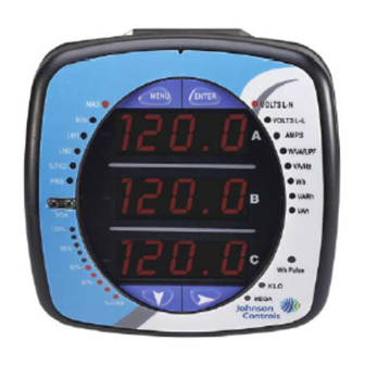
EM-3000 Series Meter Quickstart Guide
Front Cover
Support fitted
into its base
Wireless Ethernet Connection
Current
Electronic Circuits
Inputs
Ia Ia Ib Ib Ic Ic
(+) (-) (+) (-) (+) (-)
Va Vb Vc Vn L1 L2 PE
Voltage
Inputs
Access Holes for
Wiring
Select wiring diagram to meet your application. See User Manual for additional wiring diagrams.
A
B
C
N
Ic
Ib
Ia
Ia Ia Ib Ib Ic Ic
(+) (-) (+) (-) (+) (-)
A
B
C
N
IMPORTANT!
on the left. The front cover support fits into its base. Make sure
the support is up before closing the front cover.
Ethernet, RJ45
Jack
JP2
RS485 Output
(Do not put the
Voltage on these
terminals!)
Z K Y + - SH
RS485
KYZ Pulse
Output
Power Supply
Inputs (Inputs
are unipolar)
L2 is for Neutral
Electronic Circuits
Va Vb Vc Vref L1 L2 PE
Power Supply Inputs
L2 is for Neutral
WYE Direct, 3
Phase, 4 Wire
EM-3000 Series Meter Quickstart Guide
Code No. LIT-12011870
Issued October 25, 2013
WARNING!
During normal operation of the meter
dangerous voltages flow through many parts of the meter,
including Terminals and any connected CTs and PTs, all I/O
modules and their circuits. All Primary and Secondary
circuits can, at times, produce lethal voltages and
currents. Avoid contact with any current-carrying surfaces.
Before performing ANY work on the EM-3000 Series
meter, make sure the meter is powered down and
ALL circuits are de-energized.
All wiring is done with the cover open, as shown
Detail of JP2 Board and
LAN/485 Setting
A
B
C
N
Ic
Ib
Ia
Ia Ia Ib Ib Ic Ic
(+) (-) (+) (-) (+) (-)
Va Vb Vc Vn L1 L2 PE
A
B
C
N
NOTE: Jumper 2 (JP2)
must be set for either
RS485 or Ethernet commu-
nication (see figures on the
left for location of JP2 and
settings). Put the jumper
on positions 2 and 3 for
LAN (Ethernet) communi-
cation, or on 1 and 2 for
RS485 communication.
Electronic Circuits
Power Supply Inputs
WYE with PTs, 3
Phase, 4 Wire
QS - 1
Advertisement

Related Manuals for Johnson Controls EM-3000 Series


Summary of Contents for Johnson Controls EM-3000 Series
- Page 1 All Primary and Secondary circuits can, at times, produce lethal voltages and currents. Avoid contact with any current-carrying surfaces. Before performing ANY work on the EM-3000 Series Front Cover meter, make sure the meter is powered down and Support fitted ALL circuits are de-energized.
- Page 2 1.Push the MENU button - you will see the display on the right; rSt will be blinking. 2.Press the DOWN ARROW once. CFG (Configuration) moves to the top of the display. MENU ENTER 3.Press the ENTER button. You will see the Configuration menu, shown on the right. EM-3000 Series Meter Quickstart Guide QS - 2...
- Page 3 ARROW to move to the next digit. Repeat until the setting is done. Valid address- es are from 001 through 247. If you are using the Ethernet option, do NOT change anything on this screen. EM-3000 Series Meter Quickstart Guide QS - 3...
- Page 4 Pt-n value as 345, Pt-d value as 69, Pt-S value as 1000. Refer to the EM-3000 Series Meter Installation and Operation Manual (LIT-12011874) for important product application information. Also refer to the manual for additional wiring options and program- ming information.
Need help?
Do you have a question about the EM-3000 Series and is the answer not in the manual?
Questions and answers