
Related Manuals for Johnson Controls Mercury 3 Series


Summary of Contents for Johnson Controls Mercury 3 Series
- Page 1 P2000 Security Management System hardware installation CKM-MR52-S3 authentic Mercury™ terminal module 24-10707-198 Revision – December 2017...
- Page 2 If this document is translated from the original English version by Johnson Controls, all reasonable endeavors will be used to ensure the accuracy of translation. Johnson Controls shall not be liable for any translation errors contained herein or for incidental or consequential damages in connection with the furnishing or use of this translated material.
- Page 3 Declarations of Conformity United States: This equipment has been tested and found to comply with the limits for a Class A digital device, pursuant to part 15 of the FCC Rules. These limits are designed to provide reasonable protection against harmful interference when the equipment is operated in a commercial environment.
- Page 4 UNDERWRITERS LABORATORIES COMPLIANCE VERIFICATION SHEET The following model number is listed under Underwriters Laboratories® (UL) 1076 for Proprietary Burglar Alarm Units and Systems, UL 294 for Access Control Systems Units and Underwriters Laboratories of Canada ULC/ORD-C1076-86. CKM-MR52-S3 When installed at the site the following requirements must be met to comply with these standards. 1.
-
Page 5: General Information
CKM-MR52-S3 Hardware Installation Manual 24-10707-198 Rev. – CKM-MR52-S3 R EADER ERMINAL ODULE This document provides hardware installation and setup instructions for CKM-MR52-S3, the authentic Mercury™ dual reader terminal module Series 3. This document is divided into the following sections: • General Information on page 1 •... -
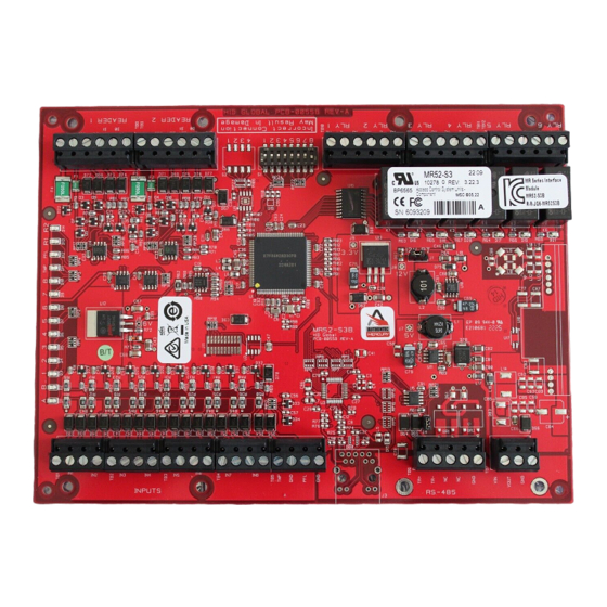
Page 6: Mounting Information
CKM-MR52-S3 Hardware Installation Manual 24-10707-198 Rev. – OUNTING NFORMATION Figure 1: CKM-MR52 Hardware IRING NFORMATION This sections covers the following: • Cable Routing • Power Wiring • Communications Wiring (SIO Communication Port) • Reader Wiring • Alarm Contact Wiring • Control Output Wiring... - Page 7 CKM-MR52-S3 Hardware Installation Manual 24-10707-198 Rev. – Cable Routing The cables should run in grounded conduit or at least two feet from AC power, fluorescent lights, or other high energy sources. : All data cables should be physically separated from power lines. If MPORTANT conduit is used, do not run data cables in the same conduit as power cables or certain door strike cables, e.g.
- Page 8 CKM-MR52-S3 Hardware Installation Manual 24-10707-198 Rev. – Communications Wiring (SIO Communication Port) The CKM-MR52 communicates to an intelligent controller (for example, CKM-EP2500) via a 2-wire RS-485 interface. The CKM-MR52 allows for multidrop communication on a bus of up to 4,000 feet (1,200 m). Use twisted pairs (minimum 24 AWG) with drain wire and shield for communication.
- Page 9 CKM-MR52-S3 Hardware Installation Manual 24-10707-198 Rev. – To fully utilize each reader port: • TTL signaling requires a 6-conductor cable (18 AWG) • RS-485 signaling requires two 2-conductor cables. Use one cable for power (18 AWG) and one cable for communication (24 AWG, with drain wire and shield).
- Page 10 CKM-MR52-S3 Hardware Installation Manual 24-10707-198 Rev. – Alarm Contact Wiring There are 8 inputs that are typically used to monitor door position, request to exit or alarm contacts. Input circuits can be configured as: • Unsupervised alarm (2 states); reporting as open or closed contact. •...
- Page 11 CKM-MR52-S3 Hardware Installation Manual 24-10707-198 Rev. – To minimize premature contact failure and to increase system reliability, contact protection circuit must be used. The following two circuits are recommended. Locate the protection circuit as close to the load as possible, within 12 inches30cm), as the effectiveness of the circuit decreases if it is located further away.
- Page 12 CKM-MR52-S3 Hardware Installation Manual 24-10707-198 Rev. – Table 1: Switches Selection OFF ON OFF OFF Address 12 OFF ON OFF ON Address 13 OFF ON OFF Address 14 OFF ON Address 15 OFF OFF OFF OFF Address 16 OFF OFF OFF ON Address 17 OFF OFF ON OFF Address 18...
-
Page 13: Status Leds
CKM-MR52-S3 Hardware Installation Manual 24-10707-198 Rev. – Table 2: Jumpers Jumper Description Reader Power Select 12V = 12 VDC at reader ports. PT = VIN “Passed Through” to reader ports RS-485 Termination, install in first and last units only. All other jumpers are for factory use only. 1. - Page 14 CKM-MR52-S3 Hardware Installation Manual 24-10707-198 Rev. – Table 3: LED Information Process LED Information Run Time 1 LED: Input Status: IN1 (continued) 2 LED: Input Status: IN2 3 LED: Input Status: IN3 4 LED: Input Status: IN4 5 LED: Input Status: IN5 6 LED: Input Status: IN6 7 LED: Input Status: IN7 8 LED: Input Status: IN8...
-
Page 15: Specifications
CKM-MR52-S3 Hardware Installation Manual 24-10707-198 Rev. – PECIFICATIONS Use this interface in low voltage, Class 2 circuits only. Table 4: CKM-MR52 Specifications Category Description Primary Power 12 to 24 VDC ±10%, 550 mA maximum Outputs Six Form-C relays: Normally open contact (NO) contact: 5 A @ 30 VDC resistive Normally closed contact (NC) contact: 3 A @ 30 VDC resistive Inputs 8 unsupervised/supervised, standard EOL: 1k/1k ohm, 1% 1/4 watt... -
Page 16: Maintenance
CKM-MR52-S3 Hardware Installation Manual 24-10707-198 Rev. – Table 4: CKM-MR52 Specifications Category Description Environmental Temperature 32 to 120°F (0 to 49°C) operating -67 to 185°F (-55 to 85°C) storage Humidity 10 to 93% RHNC Mechanical Dimensions 6 in. x 8 in. x 1 in. (15.2 cm x 20.3 cm x 2.5 cm) (W x L x H) Weight 11 oz. - Page 17 Security Solutions (805) 522-5555 www.johnsoncontrols.com We welcome your comments at BE-techpubs-security@jci.com.
Need help?
Do you have a question about the Mercury 3 Series and is the answer not in the manual?
Questions and answers