
Related Manuals for Johnson Controls EM-3000 Series


Summary of Contents for Johnson Controls EM-3000 Series
- Page 1 Code No. LIT-12011874 Issued July 21, 2014 EM-3000 Series Meter Installation and Operation Manual...
- Page 2 This page intentionally left blank.
- Page 3 Johnson Controls, Inc. Metasys® and Johnson Controls® are registered trademarks of Johnson Controls, Inc. All other marks herein are the marks of their respective owners. © 2014 Johnson Controls, Inc.
- Page 4 This page intentionally left blank. EM-3000 Series Meter Installation and Operation Manual...
-
Page 5: Use Of Product For Protection
Statement of Calibration Our instruments are inspected and tested in accordance with specifications published by Johnson Controls, Inc. The accuracy and a calibration of our instruments are trace- able to the National Institute of Standards and Technology through equipment that is calibrated at planned intervals by comparison to certified standards. -
Page 6: Fcc Information
• The antenna provided must not be replaced with a different type. Attaching a different antenna will void the FCC approval and the FCC ID can no longer be considered. EM-3000 Series Meter Installation and Operation Manual... -
Page 8: Table Of Contents
1.3: Reactive Energy and Power Factor 1-12 1.4: Harmonic Distortion 1-14 1.5: Power Quality 1-17 2: EM-3000 Series Meter Overview and Specifications 2.1: Hardware Overview 2.1.1: Model Number plus Option Numbers 2.1.2: Measured Values 2.1.3: Utility Peak Demand 2.2: Specifications 2.3: Compliance... - Page 9 5.1.2: KYZ Output 5.1.3: Ethernet Connection 6: Ethernet Configuration 6.1: Introduction 6.2: Factory Default Settings 6.2.1: Modbus/TCP to RTU Bridge Setup 6.3: Configure Network Module 6.3.1: Configuration Requirements 6.3.2: Configuring the Ethernet Adapter EM-3000 Series Meter Installation and Operation Manual TOC-2...
- Page 10 Table of Contents 6.3.3: Detailed Configuration Parameters 6.3.4: Setup Details 6.4: Network Module Hardware Initialization 6-14 6.5: Integrating the EM-3000 Series Meter into a WLAN 6-15 7: Using the Submeter 7.1: Introduction 7.1.1: Understanding Submeter Face Elements 7.1.2: Understanding Submeter Face Buttons 7.2: Using the Front Panel...
- Page 11 A.1: Introduction A.2: Navigation Maps (Sheets 1 to 4) B: EM-3000 Series Meter’s Modbus Map B.1: Introduction B.2: Modbus Register Map Sections B.3: Data Formats B.4: Floating Point Values B.5: Modbus Register Map EM-3000 Series Meter Installation and Operation Manual TOC-4...
-
Page 12: 1: Three-Phase Power Measurement
This leads to common voltages of 208/ 120 and 480/277 (where the first number represents the phase-to-phase voltage and the second number represents the phase-to-ground voltage). EM-3000 Series Meter Installation and Operation Manual 1 - 1... - Page 13 A phasor diagram for the typical connected voltages and currents is shown in Figure 1.2. Figure 1.2: Phasor Diagram Showing Three-phase Voltages and Currents EM-3000 Series Meter Installation and Operation Manual 1 - 2...
- Page 14 The transformer is the best place to determine the circuit connection type because this is a location where the voltage reference to ground can be conclusively identified. EM-3000 Series Meter Installation and Operation Manual 1 - 3...
-
Page 15: 2: Delta Connection
In many delta services, one corner of the delta is grounded. This means the phase to ground voltage will be zero for one phase and will be full phase-to-phase voltage for the other two phases. This is done for protective purposes. EM-3000 Series Meter Installation and Operation Manual 1 - 4... - Page 16 208 volts on the third phase. Figure 1.5 shows the phasor diagram for the voltages in a three-phase, four-wire delta system. Figure 1.5: Phasor Diagram Showing Three-phase Four-Wire Delta-Connected System EM-3000 Series Meter Installation and Operation Manual 1 - 5...
-
Page 17: 3: Blondel's Theorem And Three Phase Measurement
The difference in modern meters is that the digital meter measures each phase volt- age and current and calculates the single-phase power for each phase. The meter then sums the three phase powers to a single three-phase reading. EM-3000 Series Meter Installation and Operation Manual 1 - 6... - Page 18 Kirchhoff's Law and it is not necessary to measure it. This fact leads us to the conclusion of Blondel's Theorem- that we only need to measure the power in three of EM-3000 Series Meter Installation and Operation Manual 1 - 7...
-
Page 19: Power, Energy And Demand
The data from Figure 1.7 is reproduced in Table 2 to illustrate the calculation of energy. Since the time increment of the measurement is one minute and since we EM-3000 Series Meter Installation and Operation Manual 1 - 8... - Page 20 1/ 60 (converting the time base from minutes to hours). Time (minutes) Figure 1.7: Power Use over Time EM-3000 Series Meter Installation and Operation Manual 1 - 9...
- Page 21 15-minute interval. To convert the reading to a demand value, it must be normalized to a 60-minute interval. If the pattern were repeated for an additional three 15-minute intervals the total energy would be four times the measured value or EM-3000 Series Meter Installation and Operation Manual 1 - 10...
- Page 22 As can be seen from this example, it is important to recognize the relationships between power, energy and demand in order to control loads effectively or to monitor use correctly. EM-3000 Series Meter Installation and Operation Manual 1 - 11...
-
Page 23: Reactive Energy And Power Factor
The quadrature current may be lagging the voltage (as shown in Figure 1.9) or it may lead the voltage. When the quadrature current lags the voltage the load is requiring both real power (watts) and reactive power (VARs). When the quadrature current EM-3000 Series Meter Installation and Operation Manual 1 - 12... - Page 24 It is solely based on the phase angle differences. As a result, it does not include the impact of EM-3000 Series Meter Installation and Operation Manual 1 - 13...
-
Page 25: Harmonic Distortion
Figure 1.11 shows a current waveform with a slight amount of harmonic distortion. The waveform is still periodic and is fluctuating at the normal 60 Hz frequency. However, the waveform is not a smooth sinusoidal form as seen in Figure 1.10. EM-3000 Series Meter Installation and Operation Manual 1 - 14... - Page 26 Figure 1.11. 1000 Time 3rd harmonic 5th harmonic – 500 7th harmonic Total fundamental Figure 1.12: Waveforms of the Harmonics EM-3000 Series Meter Installation and Operation Manual 1 - 15...
- Page 27 It is common in advanced meters to perform a function commonly referred to as waveform capture. Waveform capture is the ability of a meter to capture a present picture of the voltage or current waveform for viewing and harmonic analysis. EM-3000 Series Meter Installation and Operation Manual 1 - 16...
-
Page 28: Power Quality
In his book Power Quality Primer, Barry Kennedy provided information on different types of power quality problems. Some of that information is summarized in Table 1.3. EM-3000 Series Meter Installation and Operation Manual 1 - 17... - Page 29 If a power quality problem is suspected, it is generally wise to consult a power quality professional for assistance in defining the cause and possible solutions to the problem. EM-3000 Series Meter Installation and Operation Manual 1 - 18...
-
Page 30: 2: Em-3000 Series Meter Overview And Specifications
The EM-3000 Series meter is a traceable revenue meter and contains a utility grade test pulse to verify rated accu- racy. - Page 31 • IrDA port for laptop PC remote read • Direct interface with most Building Management systems The EM-3000 Series meter uses standard 5 or 1 Amp CTs (either split or donut). It surface mounts to any wall and is easily programmed. The unit is designed specifi- cally for easy installation and advanced communication.
-
Page 32: 1: Model Number Plus Option Numbers
EM-3000 Series meter with a 60Hz system, default power sup- ply, 5 Amp Secondary current class, default mounting, and default V-Switch key. The last two options do not pertain to the EM-3000 Series meter, so the ordering code contains 0s for them. -
Page 33: 2: Measured Values
2: Meter Overview and Specifications 2.1.2: Measured Values The EM-3000 Series meter provides the following measured values all in real time and some additionally as average, maximum and minimum values. EM-3000 Series Meter Measured Values Measured Values Real Time Average... -
Page 34: 3: Utility Peak Demand
2: Meter Overview and Specifications 2.1.3: Utility Peak Demand The EM-3000 Series meter provides user-configured Block (Fixed) window or Rolling window Demand. This feature allows you to set up a customized Demand profile. Block window Demand is Demand used over a user-configured Demand period (usu- ally 5, 15 or 30 minutes). - Page 35 For Example, an EM-3860-05-WE00 that has a 5 Amp secondary that is used to measure a 400A load would need current transformers with a 400/5 ratio. Isolation All Inputs and Outputs are galvanically isolated and tested to 2500VAC EM-3000 Series Meter Installation and Operation Manual 2 - 6...
- Page 36 @60Hz All other parameters: Every 60 cycles, e.g, 1 second @60Hz Communication Format IrDA Port through Face Plate Protocol: Modbus ASCII Com Port Baud Rate: 57600 bps Com Port Address: EM-3000 Series Meter Installation and Operation Manual 2 - 7...
- Page 37 Solid State – SPDT (NO – C – NC) Relay type: Solid state Peak switching voltage: DC ±350V Continuous load current: 120mA Peak load current: 350mA for 10ms On resistance, max.: 35Ω Leakage current: 1µA@350V Isolation: AC 3750V EM-3000 Series Meter Installation and Operation Manual 2 - 8...
- Page 38 P[Watt] - Not a scaled value pulse Kh – See Section 7-4 for values Watt IR LED Light Pulses Through face plate 40ms 40ms (De-energized state) KYZ output Contact States Through Backplate EM-3000 Series Meter Installation and Operation Manual 2 - 9...
-
Page 39: Compliance
• ANSI C62.41 (Burst) • EN61000-6-2 Immunity for Industrial Environments: 2005 • EN61000-6-4 Emission Standards for Industrial Environments: 2007 • EN61326-1 EMC Requirements: 2006 • UL Listed • CE Compliant EM-3000 Series Meter Installation and Operation Manual 2 - 10... -
Page 40: Accuracy
20% of the values listed in the table. For unbalanced voltage inputs where at least one crosses the 150V auto-scale threshold (for example, 120V/120V/208V system), degrade accuracy by additional 0.4%. EM-3000 Series Meter Installation and Operation Manual 2 - 11... - Page 41 2: Meter Overview and Specifications This page intentionally left blank. EM-3000 Series Meter Installation and Operation Manual 2 - 12...
-
Page 42: 3: Mechanical Installation
3: Mechanical Installation 3: Mechanical Installation 3.1: Overview The EM-3000 Series meter can be installed on any wall. See Chapter 4 for wiring diagrams. Mount the meter in a dry location, which is free from dirt and corrosive substances. Recommended Tools for EM-3000 Series meter Installation •... -
Page 43: Install The Base
Front Cover Support Figure 3.1: EM-3000 Series Meter with Cover Open: see WARNING! on previous page CAUTIONS! • Remove the antenna before opening the unit. • Only use the front cover support if you are able to open the front cover to the extent that you can fit the front cover support into its base. -
Page 44: 1:Mounting Diagrams
3: Mechanical Installation 3.2.1:Mounting Diagrams Figure 3.2: Mounting Plate Dimensions EM-3000 Series Meter Installation and Operation Manual 3 - 3... - Page 45 3: Mechanical Installation Figure 3.3: Front Dimensions EM-3000 Series Meter Installation and Operation Manual 3 - 4...
- Page 46 3: Mechanical Installation Figure 3.4: Side Dimensions EM-3000 Series Meter Installation and Operation Manual 3 - 5...
- Page 47 3: Mechanical Installation 12”/ 30.4cm Figure 3.5: Open Cover Dimensions Figure 3.6: Bottom View with Access Holes EM-3000 Series Meter Installation and Operation Manual 3 - 6...
-
Page 48: Secure The Cover
(see figures 3.6 and 3.7). 4. Reattach the antenna, if applicable. Closed Screw Lockable Revenue Seal Figure 3.7: Submeter with Closed Cover EM-3000 Series Meter Installation and Operation Manual 3 - 7... - Page 49 3: Mechanical Installation This page intentionally left blank. EM-3000 Series Meter Installation and Operation Manual 3 - 8...
-
Page 50: 4: Electrical Installation
4: Electrical Installation 4: Electrical Installation 4.1: Considerations When Installing Meters Installation of the EM-3000 Series meter must be performed only by qualified personnel who follow standard safety precautions during all procedures. Those personnel should have appropriate training and experience with high voltage devices. Appropriate safety gloves, safety glasses and protective clothing is recommended. - Page 51 4: Electrical Installation Do not HIPOT/Dielectric test any Outputs, Inputs or Communications terminals. Johnson Controls, Inc. recommends the use of Fuses for voltage leads and power supply and Shorting Blocks to prevent hazardous voltage conditions or damage to CTs, if the meter needs to be removed from service.
- Page 52 Les entrées actuelles doivent seulement être branchées aux transformateurs externes actuels. Johnson Controls recommande d'utiliser les fusibles pour les fils de tension et alimen- tations électriques, ainsi que des coupe-circuits pour prévenir les tensions dangere- uses ou endommagements de transformateur de courant si l'unité EM-3000 Series doit être enlevée du service.
- Page 53 DANS L'UTILISATION FINALE DE L'ÉQUIPEMENT OU L'INSTALLATION. L'INTERRUPTEUR DOIT ÊTRE DANS UNE PROXIMITÉ PROCHE DE L'ÉQUIPEMENT ET A LA PORTÉE DE L'OPÉRATEUR. L'INTERRUPTEUR DOIT AVOIR LA MENTION DÉBRANCHEMENT DE L'APPAREIL POUR L'ÉQUIPEMENT. EM-3000 Series Meter Installation and Operation Manual 4 - 4...
-
Page 54: Electrical Connections
4: Electrical Installation 4.2: Electrical Connections All wiring for the EM-3000 Series meter is done through the front of the unit (lifting the cover with the power to the unit OFF) so that the unit can be surface mounted. Connecting cables exit the unit via two openings in the base plate (see figures 3.6 and 4.1). -
Page 55: Ground Connections
Effectuer la mise à terre selon les règlements locaux, nationaux et régionaux. La non mise à la terre du compteur peut provoquer une décharge électrique, des blessures graves ou provoquer la mort. EM-3000 Series Meter Installation and Operation Manual 4 - 6... -
Page 56: Voltage Fuses
4: Electrical Installation 4.4: Voltage Fuses Johnson Controls, Inc. recommends the use of fuses on each of the sense voltages and on the control power, even though the wiring diagrams in this chapter do not show them. • Use a 0.1 Amp fuse on each Voltage input. - Page 57 Ia+ Ia- Ib+ Ib- Ic+ Ic- Shorting Block Earth Ground Vref FUSES 3 x 0.1A Power Supply Connection LOAD Select: "3 EL WYE" (3 Element Wye) in Meter Programming setup. EM-3000 Series Meter Installation and Operation Manual 4 - 8...
- Page 58 4: Electrical Installation 1a. Dual Phase Hookup LINE Electronic Circuits Ia+ Ia- Ib+ Ib- Ic+ Ic- Shorting Block Earth Ground Vref FUSES 2x 0.1A Power Supply Connection LOAD EM-3000 Series Meter Installation and Operation Manual 4 - 9...
- Page 59 4: Electrical Installation 1b. Single Phase Hookup LINE Electronic Circuits Ia+ Ia- Ib+ Ib- Ic+ Ic- Shorting Block Earth Ground Vref FUSE 0.1A Power Supply Connection LOAD EM-3000 Series Meter Installation and Operation Manual 4 - 10...
- Page 60 Ia+ Ia- Ib+ Ib- Ic+ Ic- Shorting Block Earth Ground Vref FUSES 2 x 0.1A Power Supply Connection LOAD Select: "2.5 EL WYE" (2.5 Element Wye) in Meter Programming setup. EM-3000 Series Meter Installation and Operation Manual 4 - 11...
- Page 61 Ib+ Ib- Ic+ Ic- Shorting Block Earth Ground Vref FUSES 3 x 0.1A Power Supply Connection Earth Ground LOAD Select: "3 EL WYE" (3 Element Wye) in Meter Programming setup. EM-3000 Series Meter Installation and Operation Manual 4 - 12...
- Page 62 Shorting Block Earth Ground Vref FUSES 2 x 0.1A Power Supply Connection Earth Ground LOAD Select: "2.5 EL WYE" (2.5 Element Wye) in Meter Programming setup. Not Connected to Meter EM-3000 Series Meter Installation and Operation Manual 4 - 13...
- Page 63 Ic+ Ic- Shorting Block Earth Ground Vref FUSES 3 x 0.1A Power Supply Connection LOAD Select: "2 Ct dEL" (2 CT Delta) in Meter Programming setup. Not Connected to Meter EM-3000 Series Meter Installation and Operation Manual 4 - 14...
- Page 64 Ic+ Ic- Shorting Block Earth Ground Vref FUSES 3 x 0.1A Power Supply Connection LOAD Select: "2 Ct dEL" (2 CT Delta) in Meter Programming setup. Not Connected to Meter EM-3000 Series Meter Installation and Operation Manual 4 - 15...
- Page 65 Shorting Block Earth Ground Vref FUSES 2 x 0.1A Power Supply Connection Earth Ground LOAD Select: "2 Ct dEL" (2 CT Delta) in Meter Programming setup. Not Connected to Meter EM-3000 Series Meter Installation and Operation Manual 4 - 16...
- Page 66 Shorting Block Earth Ground Vref FUSES 2 x 0.1A Power Supply Connection Earth Ground LOAD Select: "2 Ct dEL" (2 CT Delta) in Meter Programming setup. Not Connected to Meter EM-3000 Series Meter Installation and Operation Manual 4 - 17...
- Page 67 NOTE: Even if the meter is used for only Amp readings, the unit requires a Volts AN reference. Please make sure that the Voltage input is attached to the meter. AC Con- trol Power can be used to provide the reference signal. EM-3000 Series Meter Installation and Operation Manual 4 - 18...
- Page 68 NOTE: Even if the meter is used for only Amp readings, the unit requires a Volts AN reference. Please make sure that the Voltage input is attached to the meter. AC Con- trol Power can be used to provide the reference signal. EM-3000 Series Meter Installation and Operation Manual 4 - 19...
- Page 69 NOTE: Even if the meter is used for only Amp readings, the unit requires a Volts AN reference. Please make sure that the Voltage input is attached to the meter. AC Con- trol Power can be used to provide the reference signal. EM-3000 Series Meter Installation and Operation Manual 4 - 20...
-
Page 70: 5: Communication Installation
5: Communication Installation 5.1: EM-3000 Series Meter Communication The EM-3000 Series meter provides two independent communication ports plus a KYZ pulse output. The first port, Com 1, is an IrDA Port, which uses Modbus ASCII. The second port, Com 2, provides RJ45 Ethernet or WiFi Ethernet communication (see Chapter 6 for Ethernet configuration). -
Page 71: 2: Kyz Output
The KYZ Pulse Output is located on the face of the meter, under the cover (see figure on the next page). WARNING! During normal operation of the EM-3000 Series meter, dangerous voltages flow through many parts of the meter, including:... - Page 72 Ia Ia Ib Ib Ic Ic (+) (-) (+) (-) (+) (-) RS-485 Z K Y + - SH Va Vb Vc Vn L1 L2 PE To Other Devices Pulse Contacts EM-3000 Series Meter Installation and Operation Manual 5 - 3...
-
Page 73: 3: Ethernet Connection
5: Communication Installation 5.1.3: Ethernet Connection In order to use the EM-3000 Series meter’s Ethernet, JP2 must be set to positions 2-3. With this setting, you can use either wired Ethernet or WiFi. • For wired Ethernet, use Standard RJ45 10/100BaseT cable to connect to the EM-3000 Series meter. - Page 74 Va Vb Vc Vn L1 L2 PE To Other Devices • Refer to Chapter 6 for instructions on how to set up the Network Module. **See diagram on next page for detailed view EM-3000 Series Meter Installation and Operation Manual 5 - 5...
- Page 75 5: Communication Installation Setting EM-3000 Series Meter Installation and Operation Manual 5 - 6...
-
Page 76: 6: Ethernet Configuration
6: Ethernet Configuration 6.1: Introduction The EM-3000 Series meter has an option for a WiFi (Wireless) or RJ45 Ethernet con- nection. The WiFi option lets you set up the submeter for use in a LAN (Local Area Network), using standard WiFi base stations. Meter configuration for these connec- tions is easily accomplished through your PC using Telnet connections. -
Page 77: Factory Default Settings
6.2: Factory Default Settings The settings shown in Section 6.2.1 are the default settings for the EM-3000 Series meter: they are the settings programmed into your meter when it is shipped to you. -
Page 78: 1: Modbus/Tcp To Rtu Bridge Setup
Slave Addr/Unit Id Source....Modbus/TCP header Modbus Serial Broadcasts....Disabled (Id=0 auto-mapped to 1) MB/TCP Exception Codes....Yes (return 00AH and 00BH) Char, Message Timeout.......00050msec, 05000msec 6) WLAN Settings: WLAN..........Disabled, network:LTRX_IBSS Topology..........AdHoc, Country: US, Channel: 11 EM-3000 Series Meter Installation and Operation Manual 6 - 3... -
Page 79: Configure Network Module
Select Command or parameter set (1..7) to change: 6.3: Configure Network Module These procedures detail how to set up the EM-3000 Series meter on the Network Module. Only one person at a time can be logged into the network port. This eliminates the possibility of several people trying to configure the Ethernet interface simultaneously. -
Page 80: 2: Configuring The Ethernet Adapter
6: Ethernet Configuration meter's Network Module. You may have to configure the Ethernet adapter in order to use it with the EM-3000 Series meter's Network Module, using the instructions in Section 6.4.2. • If you have multiple Ethernet adapters (network cards) installed on your computer, you must choose, configure and use the correct one to access the Network Module. - Page 81 6: Ethernet Configuration 2. Right click on the Local Area Network connection you will be using to connect to the EM-3000 Series meter, and select Properties from the pull-down menu. You will see a screen similar to the one shown below.
- Page 82 Enter 10.0.0.2 in the IP Address field. b. Enter 255.255.255.0 in the Subnet Mask field. 3. Click the OK button. 4. You can now close the Local Area Connection Properties and Network Connection windows. EM-3000 Series Meter Installation and Operation Manual 6 - 7...
-
Page 83: 3: Detailed Configuration Parameters
10.0.0.1 9999 and press the Enter key. NOTE: Be sure to include a space between the IP address and 9999. You will see the following information. 4. Press Enter. EM-3000 Series Meter Installation and Operation Manual 6 - 8... -
Page 84: 4: Setup Details
WLAN Settings Detail (6) (The settings shown are recommended by for use with the EM-3000 Series meter. You will only be able to access these settings if you have set Network Mode to “1” (to select Wireless mode) in the Network IP Settings Detail, shown previously.) - Page 85 Wired Equivalent Privacy portion of IEEE 802.11b/g. WEP Key Provider Steps 1. Input 26 alphanumeric characters as your Passphrase. IMPORTANT! Remember your Passphrase. PASSPHRASE TO HEXADECIMAL WEP KEYS Enter the passphrase below. 1009egbck001036ab Generate keys EM-3000 Series Meter Installation and Operation Manual 6 - 10...
- Page 86 Max Failed Packets (6-64, 255=disable) <6>? 6 • If you select “2” (WPA), you will make the following settings: Change Key <N> Y Display Key <N> N Key Type 0=hex, 1=passphrase <0> 1 EM-3000 Series Meter Installation and Operation Manual 6 - 11...
- Page 87 Encryption: 0=CCMP, 1=CCMP+TKIP, 2=CCMP+WEP, 3=TKIP, 4=TKIP+WEP <3> ? (Set the type to the minimum required security level. The “+” sign indi- cates that the group (broadcast) encryption method is different from the pair- EM-3000 Series Meter Installation and Operation Manual 6 - 12...
- Page 88 Port 77FEh to prevent users from accessing the setup from the network.) Enable Enhanced Password <N> ? N Exiting the screen CAUTION! DO NOT PRESS 'D': that will restore the Default Settings. Press 'S' to Save the settings you've entered. EM-3000 Series Meter Installation and Operation Manual 6 - 13...
-
Page 89: Network Module Hardware Initialization
AVERTISSEMENT! Pendant le fonctionnement normal du compteur EM-3000 Series des tensions dangereuses suivant de nombreuses pièces, notamment, les bornes et tous les EM-3000 Series Meter Installation and Operation Manual... -
Page 90: Integrating The Em-3000 Series Meter Into A Wlan
EM-3000 Series meter, to be connected to a wired network. To integrate the EM-3000 Series meter into a WLAN, you must first set up the WAP it will be configured with. For this you will need: •... - Page 91 WAP’s Internet IP address. The WAP then needs to direct all traffic on this port to the EM-3000 Series meter’s LAN address. This map- ping is accomplished using the port forwarding settings on the WAP, set through the...
- Page 92 6: Ethernet Configuration a. Give the port forwarding setting a meaningful name such as "EM-3000 Series meter’s Port Access" and enter the EM-3000 Series meter’s LAN IP address. b. Enter port 502 for both TCP and UDP protocols; deactivate any inbound filters.
- Page 93 6: Ethernet Configuration This page intentionally left blank. EM-3000 Series Meter Installation and Operation Manual 6 - 18...
-
Page 94: 7: Using The Submeter
7: Using the Submeter 7.1: Introduction The EM-3000 Series meter can be configured and a variety of functions can be accom- plished by using the Elements and the Buttons on the submeter face. This chapter reviews front panel navigation. See Appendix A for complete Navigation maps. -
Page 95: 2: Understanding Submeter Face Buttons
• Configure Parameters (may be Password Protected) • Perform Resets (may be Password Protected) • Perform LED Checks • Change Settings • View Parameter Values • Scroll Parameter Values • View Limit States (V-4) EM-3000 Series Meter Installation and Operation Manual 7 - 2... -
Page 96: Using The Front Panel
7: Using the Submeter 7.2: Using the Front Panel You can access four modes using the EM-3000 Series meter’s front panel buttons: • Operating mode (Default) • Reset mode • Configuration mode • Information mode - Information mode displays a sequence of screens that show model information, such as Frequency, Amps, V-Switch, etc. -
Page 97: 2: Using The Main Menu
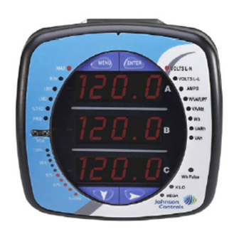
MEGA %LOAD Figure 7.3: Display Showing Watt-hr Reading The EM-3000 Series meter continues to provide scrolling readings until one of the buttons on the front panel is pressed, causing the meter to enter one of the other Modes. 7.2.2: Using the Main Menu 1. -
Page 98: 3: Using Reset Mode
To enter a password, follow the instructions in Section 7.2.4. 2. Once you have performed a reset, the screen displays MENU ENTER “rSt ALL donE” and then resumes auto-scrolling parameters. EM-3000 Series Meter Installation and Operation Manual 7 - 5... -
Page 99: 4: Entering A Password
ENTER appears and: • The previous screen is re-displayed, if you are in Reset Mode. • The previous Operating mode screen is re-dis- played, if you are in Configuration mode. EM-3000 Series Meter Installation and Operation Manual 7 - 6... -
Page 100: 5: Using Configuration Mode
Parameter you want is in A window 6. The parameter screen appears, showing the current settings. To change the settings: • Use either the Down button or the Right button to select an option. EM-3000 Series Meter Installation and Operation Manual 7 - 7... - Page 101 Press the Enter button to save Press the Enter button to The settings have been the settings. Press the Right Cancel the Save. saved. button for Stor All no screen. EM-3000 Series Meter Installation and Operation Manual 7 - 8...
-
Page 102: 1: Configuring The Scroll Feature
Menu button. • To return to the Main Menu screen, press the Menu button twice. • To return to the scrolling (or non-scrolling) parameters display, press the Menu button three times. EM-3000 Series Meter Installation and Operation Manual 7 - 9... -
Page 103: 2: Configuring Ct Setting
Example CT Settings: 200/5 Amps: Set the Ct-n value for 200 and the Ct-S value for 1. 800/5 Amps: Set the Ct-n value for 800 and the Ct-S value for 1. EM-3000 Series Meter Installation and Operation Manual 7 - 10... -
Page 104: 3: Configuring Pt Setting
From the Pt-n or Pt-d screen: • Use the Down button to select the number value for a digit. • Use the Right button to move to the next digit. EM-3000 Series Meter Installation and Operation Manual 7 - 11... - Page 105 NOTE: Pt-n and Pt-S are dictated by primary voltage; Pt-d is secondary voltage. MENU ENTER MENU ENTER MENU ENTER Use buttons to set Pt-n Use buttons to set Pt-d Use buttons to select scaling EM-3000 Series Meter Installation and Operation Manual 7 - 12...
-
Page 106: 4: Configuring Connection Setting
• Access one of the other Port screens by pressing the Enter button: press Enter once to access the bAUd screen (Baud Rate), twice to access the Prot screen (Protocol). EM-3000 Series Meter Installation and Operation Manual 7 - 13... - Page 107 3. The STOR ALL YES screen appears. Press Enter to save the settings. MENU ENTER MENU ENTER MENU ENTER Use buttons to enter Address Use buttons to select Baud Rate Use buttons to select Protocol EM-3000 Series Meter Installation and Operation Manual 7 - 14...
-
Page 108: 6: Using Operating Mode
7: Using the Submeter 7.2.6: Using Operating Mode Operating mode is the EM-3000 Series meter’s default mode, that is, the standard front panel display. After starting up, the meter automatically scrolls through the parameter screens, if scrolling is enabled. Each parameter is shown for 7 seconds, with a 1 second pause between parameters. -
Page 109: Understanding The % Of Load Bar
7: Using the Submeter 7.3: Understanding the % of Load Bar The 10-segment LED bar graph at the bottom left of the EM-3000 Series meter’s front panel provides a graphic representation of Amps. The segments light according to the load, as shown in the table below. -
Page 110: Performing Watt-Hour Accuracy Testing (Verification)
To confirm the meter’s performance and calibration, power providers use field test standards to ensure that the unit’s energy measurements are correct. Since the EM-3000 Series meter is a traceable revenue meter, it contains a utility grade test pulse that can be used to gate an accuracy standard. - Page 111 Table 7.1: Infrared & KYZ Pulse Constants for Accuracy Testing - Kh Watt-hour per pulse NOTES: • Minimum pulse width is 40 milliseconds. • Refer to Chapter 2, Section 2.2, for Wh Pulse specifications. EM-3000 Series Meter Installation and Operation Manual 7 - 18...
-
Page 112: A: Em-3000 Series Meter's Navigation Maps
A.2: Navigation Maps (Sheets 1 to 4) The EM-3000 Series meter’s Navigation maps begin on the next page. The maps show in detail how to move from one screen to another and from one display mode to another using the buttons on the face of the meter. - Page 113 When a legend is blinking, either button advances to the next choice legend. all screens single group of for a display action taken button screen screens mode EM-3000 Series Meter Installation and Operation Manual A - 2...
- Page 114 VOLTS_LL AMPS_ AMPS AMPS_MAX AMPS_MIN AMPS_THD NEUTRAL W_VAR_PF W_VAR_PF W_VAR_PF W_VAR_PF W_VAR_PF _MAX_POS _MIN_POS _MAX_NEG _MIN_NEG KEY: VA_FREQ_ VA_FREQ_ VA_FREQ KWH_TOT KWH_RE C KWH_DEL KWH_NET KVARH_NET KVARH_TOT KVARH_POS KVARH_NEG KVAH EM-3000 Series Meter Installation and Operation Manual A - 3...
- Page 115 PASS min values correct? #### FAIL RESET_CONFIRM: DONE 2 sec. MENU (from any to previous operating reset mode mode screen screen) see sheet 2 to Main Menu see sheet 1 EM-3000 Series Meter Installation and Operation Manual A - 4...
- Page 116 EDIT screen 2 sec. SAVE_NO: reboot to Main Menu STOR MENU to previous operating ALL? see sheet 1 mode screen ENTER no (blinking) see sheet 2 EM-3000 Series Meter Installation and Operation Manual A - 5...
- Page 117 A: EM-3000 Series Meter’s Navigation Maps This page intentionally left blank. EM-3000 Series Meter Installation and Operation Manual A - 6...
-
Page 118: B: Em-3000 Series Meter's Modbus Map
The Modbus Map for the EM-3000 Series Meter gives details and information about the possible readings of the meter and about the programming of the meter. The EM-3000 Series can be programmed using the buttons on the face plate of the meter (Chapter 7). -
Page 119: B.4: Floating Point Values
11000100 11100001 00011101 10111001 (binary) The sign of the mantissa (and therefore the number) is 1, which represents a nega- tive value. The Exponent is 10001001 (binary) or 137 decimal. EM-3000 Series Meter Installation and Operation Manual B - 2... -
Page 120: B.5: Modbus Register Map
• Exponent = the whole number before the decimal point. • Mantissa = the positive fraction after the decimal point. B.5: Modbus Register Map The EM-3000 Series meter's Modbus register map begins on the following page. EM-3000 Series Meter Installation and Operation Manual B - 3... - Page 121 B: EM-3000 Series Meter’s Modbus Map This page intentionally left blank. EM-3000 Series Meter Installation and Operation Manual B - 4...
- Page 122 Comments Fixed Data Section Identification Block read-only -------t -----vvv -------- --ffffff Meter Data Section read-only Primary Readings Block, 6 cycles (IEEE Floating Point) read-only Primary Readings Block, 60 cycles (IEEE Floating Point) EM-3000 Series Meter Installation and Operation Manual MM-1...
- Page 123 B: Modbus Map Modbus Address Units or Decimal Description Format Range Resolution Comments read-only Primary Energy Block read-only Primary Demand Block (IEEE Floating Point) Primary Minimum Block (IEEE Floating Point) read-only EM-3000 Series Meter Installation and Operation Manual MM-2...
- Page 124 B: Modbus Map Modbus Address Units or Decimal Description Format Range Resolution Comments Primary Maximum Block (IEEE Floating Point) read-only 7, 13 read-only THD Block EM-3000 Series Meter Installation and Operation Manual MM-3...
- Page 125 B: Modbus Map Modbus Address Units or Decimal Description Format Range Resolution Comments read-only Phase Angle Block Status Block read-only --exnpch ssssssss 87654321 87654321 Commands Section write-only Resets Block read/conditional write Meter Programming Block EM-3000 Series Meter Installation and Operation Manual MM-4...
- Page 126 Range Resolution Comments Other Commands Block read/write Encryption Block read/write Programmable Settings Section Basic Setups Block write only in PS update mode dddddddd mmmmmmmm mmmmmmmm MMMMhhhh --iiiiii b----sss pppp--nn -eee-ddd 00000000 eeeeeeee EM-3000 Series Meter Installation and Operation Manual MM-5...
- Page 127 B: Modbus Map Modbus Address Units or Decimal Description Format Range Resolution Comments ---g--nn srp--wf- ----dddd -0100110 ----dddd -ppp-bbb EM-3000 Series Meter Installation and Operation Manual MM-6...
- Page 128 B: Modbus Map Modbus Address Units or Decimal Description Format Range Resolution Comments 12-Bit Readings Section 12-Bit Block read-only except as noted End of Map EM-3000 Series Meter Installation and Operation Manual MM-7...
- Page 129 B: Modbus Map Notes EM-3000 Series Meter Installation and Operation Manual MM-8...
Need help?
Do you have a question about the EM-3000 Series and is the answer not in the manual?
Questions and answers