Table of Contents
Advertisement
Quick Links
Advertisement
Table of Contents

Related Manuals for Klein + Hummel O110 D


Summary of Contents for Klein + Hummel O110 D
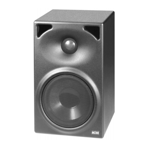
- Page 1 O110 D Active Studio Monitor Installation and Operation...
-
Page 2: Safety Instructions
Safety Instructions Safety Instructions Safety Instructions Safety Instructions Safety Instructions It is absolutely essential that you read these safety instructions carefully before connecting and using this K+H product. Your safety depends on it. Furthermore, failure to follow these instructions voids the warranty. To ensure safe operation for years to come, keep these instructions in a safe place for future reference. -
Page 3: Table Of Contents
Active Studio Monitor KLEIN + HUMMEL O 110 D Installation - Operation Figure 1: Front view of the O 110 D Figure 2: Rear panel of the O 110 D Table of Contents: Safety Instructions..........2 1.6.3 Level ATT(ENUATOR).......5 1.6.4 INPUT SELECT Switch......5 1.6.5 Equalization..........5... -
Page 4: Installation And Operation
1. Installation and Operation 1.3 Connection to Mains Power Several versions of the O110D are available for It is absolutely essential that you read different mains voltages. Please verify the label on and observe the Safety Instructions on the back side of the device is correct. If it page 2 before connecting or using this becomes necessary to use a different mains- device. -
Page 5: Bnc - Input
1.6.2 BNC - Input 1.6.2.4 Source 2x S/P-DIF or 2x AES 3id DIGITAL INPUT / THROUGH This digital input, configured as a 75-Ohm BNC connector, is intended to receive signal sources in S/P-DIF or AES 3id format. The incoming digi- tal signal line requires one 75 -Ohm terminator at the very end, as the O 110 D has no internal termination. -
Page 6: Ground Lift
result. Next to the four-position switch for room Warning! compensation which we just described, there is The protective earth conductor another four-way rotary switch labeled MID. The must never be interrupted even for four switch settings are intended for the following test purposes! This may be kinds of placement: dangerous to life! -
Page 7: Care Of The Cabinet
on the other side of which you will find the amplifier cabinet with care to avoid damaging the finish. To electronics. In Figure 5, the arrow points to the clean the cabinet, use a soft cloth with a mild spot on the input circuit board where the jumper cleaning agent only. - Page 8 Figure 8: Frequency Response (free field) Figure 9: THD, 2 nd and 3 rd order distortion @ 95 dB/SPL and 1 m distance Figure 10: Group Delay Figure 11: Cumulative Spectral Decay Plot The loudspeaker’s cumulative spectral decay plot indicates a very clean decay without any major resonances or standing waves being evident.
-
Page 9: Warranty Information
Proof of Changes or modifications to this equipment not purchase date can be made by filing copies of expressly approved by Klein + Hummel may void the appropriate documents (invoice, delivery note). FCC authorization to operate this equipment. -
Page 10: Technical Specifications
6. Technical Specifications O 110 D Maximum SPL in half space, 3% THD at 1 m distance 107.7 dB/SPL averaged between 100 Hz and 6 kHz Free field frequency response 58 Hz - 20 kHz ± 2 dB Self generated noise level at 10 cm <... - Page 11 K+H Vertriebs- und Entwicklungsgesellschaft mbH 30900 Wedemark, Germany Phone +49 (5130) 58 48 0 Fax +49 (5130) 58 48 11 www.klein-hummel.com Printed 12/07 518150...
Need help?
Do you have a question about the O110 D and is the answer not in the manual?
Questions and answers