
Related Manuals for Yamaha AR240 HO


Summary of Contents for Yamaha AR240 HO
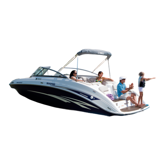
- Page 1 ar/sx 240 & 242 limited/s owner’s/operator’s manual Read this manual carefully before operating this boat.
- Page 2 State of California to cause cancer, birth defects or other reproductive harm. YAMAHA LIT-CALIF-65-01 Read this manual carefully before operating this boat. This manual should stay with the boat if sold.
- Page 3 TIP: A TIP provides key information to make procedures easier or clearer. AR240 HO, SX240HO, 242 LIMITED S, 242 LIMITED (SXT1800A-L/B-L/C-L/D-L/E-L/F-L/G-L/H-L) OWNER’S / OPERATOR’S MANUAL ©2011 by Yamaha Motor Corporation, U.S.A. 1st Edition, August 2011 All rights reserved.
- Page 5 AR240 HO, SX240 HO, 242 Limited S, & 242 Limited afety nformatIon & f eatureS unctIonS peratIon & c aIntenance rouble ecovery onSumer nformatIon...
-
Page 7: Table Of Contents
Chapter 1 SAFETY INFORMATION IDENTIFICATION NUMBER RECORDS ....1-1 Primary I.D. Number ......1-1 Hull Identification Number (H.I.N.) . -
Page 9: Safety Information
Record your Primary I.D., H.I.N., and engine numbers in the spaces provided to assist you in ordering spare parts from your Yamaha Boat dealer. Also record and keep these I.D. numbers in a separate place in case your boat is stolen. -
Page 10: Emission Control Information
REFER TO THE OWNER’S MANUAL FOR MAINTENANCE SPECIFICATIONS AND ADJUSTMENTS. FELS (HC+NOx/CO): g/kW-hr MANPOWER: kW DISPLACEMENT: liters TROLLING SPEED: SPARK PLUG: SPARK PLUG GAP (mm): FUEL: UNLEADED REGULAR GASOLINE VALVE LASH (MM) IN: YAMAHA MOTOR CO, LTD Manufactured Date Label Manufactured date label... -
Page 11: Important Labels
IMPORTANT LABELS Read the following labels before operating this boat. If you need any additional information, contact a Yamaha dealer. ... -
Page 12: Warning Labels
WARNING LABELS If any of these labels is damaged or missing, contact a Yamaha dealer for a replacement. ... - Page 13 afety nformatIon Carbon monoxide (CO) can cause brain damage or death. Engine and generator exhaust contains odorless and colorless carbon monoxide gas. Carbon monoxide will be around the back of the boat when engines or generators are running. Move to fresh air if you feel nausea, headache, dizziness, or drowsiness.
-
Page 14: Other Labels
AR240 HO / 242 LIMITED S OTHER LABELS 1980 2200 THIS BOAT COMPLIES WITH U.S. COAST GUARD SAFETY STANDARDS IN EFFECT ON THE DATE OF CERTIFICATION TENNESEE WATERCRAFT INC., VONORE, TN... -
Page 15: Safety Information
LIMITATIONS ON WHO MAY OPERATE THE BOAT • Yamaha recommends a minimum operator age of 16 years old. • Adults must supervise use by minors. -
Page 16: Required Equipment
A mirror can • Oar or paddle (look for one with a also be used as an emergency boat hook on the other end). signal. Contact your Yamaha dealer or the Coast Guard for more infor- • Spare parts, such as an extra set of fuses. -
Page 17: Cruising Limitations
afety nformatIon CRUISING LIMITATIONS • Do not operate the boat in rough water, bad weather, or when vis- • Scan constantly for people, objects, ibility is poor; this may lead to an and other watercraft. Be alert for accident causing injury or death. conditions that limit your visibility Be alert to the possibility of bad or block your vision of others. -
Page 18: Operational Requirements
afety nformatIon OPERATIONAL REQUIREMENTS • For reasons of safety and proper care of the boat, always perform • All riders must wear a Coast Guard the pre-operation checks listed on approved personal flotation device page 3-4 before operating. (PFD). • Passengers must always sit in a designated seating area, place feet on the deck, and hold on to the hand grips when the boat is in mo-... -
Page 19: Hazard Information
afety nformatIon • Attach the engine shut-off cord • Maintain a safe distance from other (lanyard) to the PFD and keep it boats or watercraft, and also watch free from the steering wheel or for boats’ ski ropes or fishing lines. other controls so that the engine Obey the “Rules of the Road”... -
Page 20: Night Operation
• This Yamaha Boat is water-jet • Stop the engines and remove the propelled. The pumps are directly clip from the engine shut-off switch connected to the engines. This before removing any debris or means that the jet thrust will pro-... -
Page 21: Water-Skiing
afety nformatIon WATER-SKIING • A second person should be on board as a spotter to watch the skier; You can use the boat to tow a water in most states, it is required by law. skier, using the tow cleat provided. Let the skier direct the operator’s It is the boat operator’s responsibility to control of speed and direction with... -
Page 22: Rules Of The Road
RULES OF THE ROAD STEERING AND SAILING RULES Whenever two vessels on the water Your Yamaha Boat is legally considered meet one another, one vessel has the a powerboat. Operation of the boat right-of-way; it is called the “stand-on”... -
Page 23: Rules When Encountering Vessels
afety nformatIon RULES WHEN ENCOUNTERING Meeting If you are meeting another power VESSELS vessel head on, and are close enough There are three main situations that to run the risk of collision, neither you may encounter with other vessels of you has the right-of-way! Both of which could lead to a collision unless you should alter course to avoid an the Steering Rules are followed:... -
Page 24: Other Special Situations
afety nformatIon Narrow Channels and Bends When navigating in narrow channels, you should keep to the right when it is safe and practical to do so. If the opera- tor of a power-driven vessel is preparing to go around a bend that may obstruct the view of other water vessels, the operator should sound a prolonged blast of four to six seconds on the horn. - Page 25 afety nformatIon “1” “3” “5” “7” LIGHTED BUOY (Port Hand) “6” C “1” Odd number, increasing toward head N “2” “7” of navigation. Leave to port (left) proceeding RB “L” White Light Green Light RG “L” “5” “4” “2” “4” “6” LIGHTED BUOY (Starboard Hand) Even number, increasing toward head of “3”...
-
Page 26: Reading Buoys And Other Markers
afety nformatIon READING BUOYS AND OTHER MARKERS The waters of the United States are marked for safe navigation by the lateral system of buoyage. Simply put, buoys and markers have an arrange- ment of shapes, colors, numbers, and lights to show which side of the buoy a boater should pass on when navi- gating in a particular direction. -
Page 27: To Get More Boating Safety Information
When travel in areas like these is unavoidable, operate slowly available through the watercraft section and obey all laws. of the yamaha-motor.com website, is a free, 50-question learning course Remember that pollution can be harm- available to the public. Upon success- ful to the environment. - Page 29 Chapter 2 FEATURES & FUNCTIONS LOCATION OF MAIN COMPONENTS ....2-1 OPERATION OF CONTROLS AND OTHER FUNCTIONS ..2-5 Steering .
-
Page 31: Features & Functions
& f eatureS unctIonS LOCATION OF MAIN COMPONENTS Main Features: Hood Supports Fuel Tank Engine Compartment Vent Outlets Battery... - Page 32 & F eatures unctions ...
- Page 33 & F eatures unctions Location of Main Components: Bow Light Bow Eye Storage Compartments Bow Anchor Locker Grab Handles Cleats Courtesy Lights / Tower Lights Fuel Compartment Access Hatch Throttle / Shift Levers Ski Locker ...
- Page 34 & F eatures unctions LOCATION OF MAIN COMPONENTS 3 4 5 3 4 5 Control Features: Speedometer Steering Wheel Tilt Adjustment Lever Tachometer Switches and Breakers Blower Switch Ignition Switches No-Wake / Cruise Assist Switch...
-
Page 35: Operation Of Controls And Other Functions
& F eatures unctions OPERATION OF TILT LEVER CONTROLS AND WARNING OTHER FUNCTIONS • Never touch the tilt lever during operation, otherwise the steering wheel could suddenly change STEERING position, which may lead to an accident. 3 4 5 3 4 5 • Be sure the steering wheel is locked in position after adjust- ment. -
Page 36: Engine Shut-Off Switch
& F eatures unctions ENGINE SHUT-OFF SWITCH WARNING • Always attach the engine shut-off cord to your Personal Flotation Device (PFD) BEFORE starting the engines. Failure to attach the cord could result in a runaway boat if the operator is ejected. • Do not attach the cord to cloth- ing that could tear loose. -
Page 37: Throttle / Shift Levers
& F eatures unctions START: The starter motor will turn to start the engine. (When the key is released, it returns automatically to “ON.”) TIP: • The engine will not start when the engine shut-off cord clip is removed from the engine stop switch. The starter motor will turn over without the cord attached. - Page 38 & F eatures unctions The drive line on the boat is direct drive, Reverse so jet thrust is always being produced The jet pump gates are dropped all the while the engines are running. The way down over the jet nozzles. Jet thrust direction of the boat is controlled by jet is redirected toward the bow of the boat, pump gates which direct the flow of the which moves the boat backward.
-
Page 39: Fuel Tank Filler Cap
& F eatures unctions FUEL TANK FILLER CAP Both tachometer faces have an LCD screen . The right (starboard) side To remove the fuel tank filler cap, turn it tachometer is the “Master” gauge and counterclockwise. the left side (port) tachometer is the “Slave” gauge. - Page 40 & F eatures unctions Pushbutton Wake Up Mode: Refers to Displayable Data Include: the state when both engines are OFF, GPS Speed - Engine RPM - Fuel Level the gauges are shut down, and the - Gallons Per Hour (GPH) - Gallons operator pushes the “M” button to see Used - Voltage - Engine Hours - Wa- the clock.
- Page 41 5) Calibrations: Calibrate systems for customization. 9) Engine Diagnostics: Display the Yamaha engine trouble code • Press the M and T buttons simul- (if any). taneously to select the item to calibrate: • To exit, press the M button or simply do nothing.
- Page 42 & F eatures unctions Warnings Warnings are audible and / or visual indicators of a fault condition. A warning will be displayed on the master gauge LCD. Warnings on the LCD can be acknowledged by pressing the M but- ton. Once acknowledged the message will disappear and be replaced by an “AL”...
-
Page 43: Engine Overheat Warning System
& F eatures unctions ENGINE OVERHEAT WARNING SYSTEM This model is equipped with an engine overheat warning system. If the engine starts to overheat, “ENGINE OVER TEMP” will appear on the LCD display of the affected engine. The buzzer also begins to sound. -
Page 44: Switches
If this occurs, reduce the engine speed, return to shore, and have Blower a Yamaha dealer check the engine. Bilge Pump Horn Low / High Battery Voltage Warning Light If either the High or Low battery ... - Page 45 & F eatures unctions Courtesy Lights Tower Lights (242 Limited S Model) This toggle switch turns on lights inside the boat. On the 242 Limited S model, press the right side of the switch to turn on both the courtesy lights and the tower lights.
- Page 46 & F eatures unctions To Set No Wake Mode: Cruise Assist Mode Press the top, plus side, of the switch The Cruise Assist feature is for steady once to set both engines in No Wake engine speed operation when the boat Mode.
-
Page 47: Swivel Seat Operation
If the button to the left of a switch pops out, push it back in with your finger. If it pops out again, ask your Yamaha dealer to inspect the electrical system. ... -
Page 48: Passenger Seats
& F eatures unctions PASSENGER SEATS To position the seat as a bench seat, lift the latch on the underside of the seat. The passenger seat on the port side Hold the seat by the straps provided of some models can be positioned in and pull the front of the seat forward two ways. -
Page 49: Stereo System
& F eatures unctions STEREO SYSTEM ENGINE HOOD A stereo receiver is standard. On AR240 There is a hood latch located under and SX240 models, the system consists the front of the rear seat. To open the of the Receiver / CD player, speakers, engine hood, lift the latch hook upward MP3 input jack and a remote control and lift the hood. -
Page 50: Storage Compartments
& F eatures unctions STORAGE COMPARTMENTS Ski Locker Your boat has convenient on-board storage areas. Bow Anchor Storage Driver’s Side Console Under Front Seats Under Rear Side Seats Pull up the seat cushions to access the storage compartments. Starboard Side Rear Compartment Pull up the seat cushions to access the and Cooler storage compartments. -
Page 51: Front Walk-Through
& F eatures unctions Port Gunwale Battery Compartment WARNING Do not carry any flammable sub- stances in the battery compartment or any heavy or metal items that can damage the battery or cause a short circuit. Sparks or fire could result. There is a light in the compartment. -
Page 52: Rear Walk-Through
& F eatures unctions Windshield SWIM PLATFORM Unsnap the retaining strap from WARNING the windshield and pivot it into place. Rotate the two latches to keep the Stay away from the swim platform windshield secured. When the wind- area while the engines are running. -
Page 53: Wakeboard Tower
& F eatures unctions WAKEBOARD TOWER (AR240 and 242 Limited S Models) The Wakeboard Tower is provided as an elevated tow point suitable for wake- boards and similar towable recreational equipment. The center pylon can be used to attach a standard ski rope or other tow rope. -
Page 54: Collapsing The Wakeboard Tower
NOTICE: Do not modify the tower to tow from any other point or to carry any ac- cessories or equipment not ap- proved by Yamaha. The tower could be damaged, AR240 COLLAPSING THE WAKEBOARD 1 Rear Tower Support TOWER... - Page 55 & F eatures unctions 5) Line up the short tower storage sup- port with the hole in the upper tower section on each side. Install the knobs, but leave them slightly loose. Once all supports and knobs are in place, tighten all knobs securely. 4) Install the upper knobs on both sides, but leave them slightly loose.
- Page 56 & F eatures unctions 242 Limited and 242 Limited S windshield secured in the open po- sition. COLLAPSING THE WAKEBOARD TOWER 3) Loosen (do not remove) the knobs on the front tower support arm on The wakeboard tower can be collapsed each side.
- Page 57 & F eatures unctions 7) Have the assistant raise or lower leave it slightly loose. Repeat on the the tower as needed until the hole in other side. the tower storage support bar aligns 5) When all knobs have been installed, from the inside with the mounting tighten all securely.
- Page 59 Chapter 3 OPERATION FUEL AND OIL....... . . 3-1 Gasoline ........3-1 Engine Oil .
-
Page 61: Operation
10% and the fuel meets minimum octane ratings. Gasohol con- taining methanol is not recommended by Yamaha because it can cause fuel system damage or engine performance problems. -
Page 62: Engine Oil
Yamaha recommends the use of Ring Free Fuel Additive, To Check the Engine Oil Level: available from your Yamaha dealer. 1) Place the watercraft in a precisely Ring Free has repeatedly proven its level position on land with the ability to clean combustion deposits engine stopped. -
Page 63: Pre-Operation Checks
If the engine oil level is Before operating this boat, perform significantly above the maximum the checks in the following check list. level mark, have a Yamaha dealer Always follow the inspection and main- service the watercraft. tenance procedures and schedules 4) Remove the engine oil filler cap . - Page 64 peratiOn ITEM CHECK PAGE REF. BEFORE LAUNCH OR OPERATION: STEERING Check for proper steering operation. THROTTLE Check for proper throttle operation. SHIFTING Check for proper shift operation. FIRE EXTINGUISHER Check readiness of the extinguishers. HULL Check the hull for damage or cracks before launching. ACCESS PORT CAPS Check for proper installation.
-
Page 65: Check Points
peratiOn CHECK POINTS Throttle / Shifters Steering 3 4 5 3 4 5 Move the control levers several times through their full range of motion. Make sure the wheel is not loose. Operation should be smooth over the There should not be any free play, complete range of motion and the either in-and-out or in rotation. - Page 66 Use this port to spray the contents equipment with this boat. If you do not of a fire extinguisher into the engine have them, contact your local Yamaha compartment if a fire breaks out in the Boat dealer or fire extinguisher dealer for engine area.
- Page 67 peratiOn extinguisher is recommended; a chem- Jet Intakes ical-type fire extinguisher may not be adequate in this application. See Fire Extinguishers above for more informa- tion. Access Port Caps Lift the hatch on the rear platform. Pull up forcefully on the T-handle of ...
- Page 68 peratiOn Fuel System Bilge Pump – Refer to page 4-10, “FUEL SYSTEM INSPECTION,” for correct procedure. Fuel and Engine Oil Levels 1) Turn the right switch key to ON. Select "Fuel Level" in the starboard gauge (see page 2-9). Add fuel if necessary. NOTE: The fuel level is most accu- rate when the boat is sitting level on the trailer or in the water.
- Page 69 peratiOn Fuel Compartment Drain Plugs – WARNING Gasoline vapors can explode. Operate blower for at least 4 minutes and Check engine compartment bilge for gasoline vapors before starting engines. Do not start engines if there is a fuel leak or loose electrical connection.
- Page 70 peratiOn Lights Horn Press the horn switch to be sure the horn operates. HORN ANCH TOWER CTLT/ HORN TOWER ANCH TOWER CTLT/ TOWER DOCKING SHOWER 242 LIMITED S MODEL SHOWN DOCKING SHOWER 242 LIMITED S MODEL SHOWN Engine Shut-Off Switch ...
- Page 71 peratiOn Cooling-Water Pilot Outlets Bimini Top SX240 and 242 Limited Check that water comes out from the Raising from the fully collapsed stor- pilot outlets while engine is running age position. in the water. Refer to page 2-13 for correct operation of the device. 1) Raise the top and secure the rear support poles to the rear support pole mounts with the lock pins.
- Page 72 Do not exceed 45 mph (72 km/h) the boat when it is being trailered. with the Bimini top in the up posi- When trailered with a Genuine Yamaha tion. Cover, simply store the Bimini top in the fully collapsed position and install Storing the cover.
- Page 73 peratiOn Bimini Top AR240 Raising from the Collapsed Position: 1) Unbuckle the cover straps from around the top of the Wakeboard Tower, then unzip and remove the storage cover. 3 Plastic Clip 4 Forward Support 4) Attach the forward support poles to the mount brackets with the spring- loaded pins 2) Zip the three flaps at the front of...
- Page 74 peratiOn 5) Collapse the front support poles removed from the tower entirely before until the snap buttons click into attempting to trailer the boat. place to tighten the top fabric. Removing the Bimini Top 1) Follow the steps for storing. 2) Remove the lock pins holding the Bimini top to the mounting brackets.
- Page 75 peratiOn 4) Unclip the plastic clips and pull the 2) Remove the spring-loaded pins. rear supports toward the stern. Ex- Push the forward support poles tend the rear supports to the long back and clip the plastic supports position (bottom button). into place on the other support poles.
-
Page 76: Operation
• Before operating your boat, become familiar with all controls. 1) Always make sure the boat is Consult your Yamaha dealer launched and used in waters that about any control or function you do not fully understand. Failure are free from weeds and debris, and at least 3 ft. - Page 77 peratiOn 2) Attach the engine shut-off cord to 3) Put the control levers in the Neutral your PFD. Install the cord clip onto position. The starter motor will not the engine shut-off switch by push- operate unless the shift lever is in ing the clip groove over the nut Neutral.
-
Page 78: Stopping The Engines
peratiOn On this boat, the engines are connected Remove the ignition keys and the directly to the drive unit. Starting either engine stop switch lanyard if the boat engine generates some thrust imme- will be left unattended. diately. Only enough throttle should be Stopping the engines immediately after applied to keep the engine at a fast operating at high rpm is not recom-... -
Page 79: Driving Your Boat
peratiOn DRIVING Know and follow U.S. Coast Guard, state, and local laws when operating YOUR BOAT your boat. Select a wide area to learn in, where GETTING TO KNOW visibility is good and other boat traffic YOUR BOAT is light. Keep the proper distance from other boats and vehicles. Do not oper- Operating your boat requires skills ate where people are swimming. -
Page 80: Turning The Boat
peratiOn TURNING THE BOAT steering wheel input until you apply throttle again or you reach a trolling WARNING speed. At trolling speed, the boat can • Do not pull the throttle levers be turned gradually by steering back to idle when trying to steer wheel position alone using just away from objects –... -
Page 81: Boating With Passengers
peratiOn BOATING WITH PASSENGERS TURNING LEFT WARNING 3 4 5 3 4 5 When passengers are on board, make sure they are seated and hold- ing on before you start to accelerate. An unprepared passenger could lose balance and fall. Your boat is designed for one opera- tor and up to nine passengers only. -
Page 82: Boarding From A Dock Or Landing Jetty
peratiOn STOPPING WARNING • You will lose steering control if you completely pull the throttles back to idle. You need throttle to steer. Do not use the reverse function • to slow down or stop the boat from planing speed as it could cause you to lose control, be ejected, or impact the steering wheel or other parts of the boat. -
Page 83: Docking
peratiOn DOCKING WIND OR CURRENT 1) Make sure no obstructions, boats or swimmers are close to the boat. Come to a stop before you reach the dock. 2) Notice how wind and water currents are affecting boat movement as you attach your mooring lines and No Wind or Current: fenders. -
Page 84: Beaching
peratiOn BEACHING Select an anchor appropriate for your boat and water conditions. A “danforth” 1) Make sure no obstructions, boats (or fluke) type anchor is suitable for or swimmers are near the beach. most applications; your dealer can help 2) Approach the beach slowly and you choose an anchor. -
Page 85: Crossing Wakes And Swells
peratiOn CROSSING WAKES AND SWELLS You will not always have flat, smooth water. There will be swells and wakes SHARP WAKES from other boats, etc. The best way to cross wakes and swells is with the least jolt to you and the boat. Small swells are not as difficult to cross as larger swells or wakes. -
Page 86: Post-Operation Checks
peratiOn POST-OPERATION 1) After putting the boat on the trailer, flush cooling system on each en- CHECKS gine to prevent the cooling system from clogging up with salt, sand, or POST-OPERATION CHECKS dirt. Refer to page 4-1 for the cool- ing system flushing procedure. - Page 87 A damaged O-ring can allow water dirt or sand, from the threads before to enter the engine compartment. installing the drain plug. 6) Spray a rust inhibitor, such as Yamaha Silicone Protectant and Lubricant, on metallic parts to minimize corrosion. 3-27...
-
Page 88: Trailering
peratiOn TRAILERING HITCH The trailer hitch ball must match the WARNING size of the socket on the trailer hitch coupler. Hitches are divided into classes Avoid accident and injury from that specify the gross trailer weight improper trailering: (GTW) and the maximum tongue •... -
Page 89: Trailering Checklist
peratiOn TRAILERING CHECKLIST • Take down and store the bimini top, if used. The top is not designed to • Check your state laws to be sure stay unsecured on the boat at high- your trailer meets all regulations, way speeds. See page 3-11, 3-12, such as proper licensing, brake, or 3-14. -
Page 90: Backing Your Trailer
peratiOn BACKING YOUR TRAILER It takes practice to back a trailer suc- cessfully. If you are not familiar backing up with a trailer, practice first in an open area away from obstacles. 1) Perform the Pre-Operation Checks shown on page 3-4 that can be per- formed on land, including operating the blower for at least 4 minutes. -
Page 91: Loading
peratiOn LOADING 6) Pull the trailer up the ramp out of the way of other boaters. Attach the 1) Disconnect the trailer lights from bow and stern tie-downs. Recon- the towing vehicle. nect the trailer lights. 2) Back the trailer down the ramp as 7) Follow the Post-Operation Checks close to 90°... -
Page 92: Lifting
peratiOn LIFTING NOTICE: Do not attach lifting cables to the bow eye, cleats, water-ski tow eye, or grab handles. Serious damage to the boat can occur. Use only a sling designed specifically for lifting boats. If you need to remove the boat from the water without a trailer, use these guide- lines: •... -
Page 93: M Aintenance & C Are
Chapter 4 MAINTENANCE AND CARE STORAGE ........4-1 Fuel System . -
Page 95: Maintenance And Care
It is advisable to have the boat serviced by an authorized Yamaha Boat dealer before storage. However, the following procedures can be performed by the owner with a minimum of tools. FUEL SYSTEM Flush Hose Connector... -
Page 96: Lubrication
There are three switches on the Battery season storage, it is recommended you Switch assembly. In normal operation, contact your Yamaha dealer for Winter- keep the Start and House switch- ization Service. es in the ON (Green) position. Keep the Emergency Parallel switch ... -
Page 97: Batteries
& c aintenance Should the Start battery become dis- For maintenance free (MF) type bat- charged the Emergency Parallel switch teries with sealed cells, check the should be rotated to the On (Green) terminal voltage monthly. When the position and the engines started. After terminal voltage drops to 12.5 VDC starting or when the discharged bat- or lower, recharge the battery with an... - Page 98 Yamalube care products are WARNING! Slippery surfaces available from your local Yamaha dealer. can cause falls and injury. Be careful not to apply too much wax on deck and gunwale step- ping surfaces. This will make...
- Page 99 & c aintenance Basic Stain Guide Here are basic steps to remove com- mon stains from boat upholstery. Consult your dealer or upholstery- cleaning professional for difficult stains. TYPE OF STAIN STEPS (rinse with clean, warm water and then dry after application) General Care/ Dirt Chewing Gum Coffee/ Tea/ Chocolate...
-
Page 100: Maintenance And Adjustments
If you are not good idea to put them in a waterproof familiar with machine servicing, this bag. If your Owner’s Manual is damaged, work should be done by a Yamaha order a replacement from a Yamaha dealer or other qualified mechanic. dealer. -
Page 101: Periodic Inspection Chart
& c aintenance PERIODIC INSPECTION CHART Frequency of maintenance operations may be adjusted according to the operating conditions, but the following table gives general guidelines. Indicates the checkups which you may do yourself. Indicates work to be done by your Yamaha dealer. Thereafter Page Initial Maintenance Interval Every... -
Page 102: Grease Points
GREASE POINTS To keep moving parts sliding or rotating smoothly, coat them with water resistant grease such as Yamaha Marine Grease, Yamaha Grease A, or an equivalent. Throttle Cable Grease the throttle-cable inner wires at the pulley wheel of the APS. - Page 103 Recommended water-resistant grease: Yamaha Marine Grease, or Yamaha Grease A The first service should be done after 10 hours or 1 month by your Yamaha dealer. Fill the bearing housing with water- resistant grease through the grease nipple. ...
-
Page 104: Fuel System Inspection
Check the fuel system for leaks, cracks, other access point is inside the port- or malfunctions. If any problem is found, side storage compartment . Remove consult a Yamaha dealer. the seat cushion then look up inside the compartment to see the fuel filler Checking Points: hose and clamp. -
Page 105: Engine Oil / Filter
The air filter element should be checked or when any water is found in the fuel every 12 months or every 100 hours of system, take the boat to your Yamaha operation. dealer for service. To Check the Air Filter: 1) Open the hood (see page 2-19). -
Page 106: Steering Cable Inspection
Neutral to wide-open throttle For- If steering is stiff or misadjusted, ask ward and from Neutral to Reverse. your Yamaha dealer to service it. Operation should be smooth. 3) While a second person watches from the stern, move the control levers to the Forward position. -
Page 107: Reverse Gate Mechanism Inspection
• Failure to replace anodes when If reverse gates do not operate smoothly necessary can result in perma- or correctly, ask your authorized Yamaha nent damage to the jet pump Boat dealer for service. outlets and other metal compo- nents on the boat. -
Page 108: Fuse Replacement
2) Clean the mounting-bolts threads, then coat them with Loctite 242, ® available from your Yamaha dealer. Cap Fuse (10A) 3) Install the new anode. Tighten the Fuse holder mounting bolts to specification. Accessory Fuses Anode Bolt Torque: 50~80 kgf-cm (47~70 inch-pounds) ... -
Page 109: Batteries
& c aintenance BATTERIES Replenishing the Battery Fluid A poorly maintained battery will dete- WARNING riorate quickly. The battery fluid should be checked before every outing. Battery electrolyte is poisonous and Fill to the manufacturer’s recommended dangerous, causing severe burns, level when necessary. - Page 110 & c aintenance Connecting the Battery Terminals Always make sure the connections are correct when you install the battery in the boat. Make sure that the breather pipe is properly connected and that it is not damaged or obstructed. ...
-
Page 111: Specifications
& c aintenance SPECIFICATIONS ITEM / MODEL UNIT AR240HO, SXT1800 (A,B,C) VEHICLE CAPACITY Maximum people on board Number of people Maximum load capacity 1980 DIMENSIONS Length feet / inches 23.63' / 283.5" Beam feet / inches 8.86' / 106.3" Draft inches 18"... - Page 112 & c aintenance SPECIFICATIONS ITEM / MODEL UNIT SX240HO, SXT1800 (D,E,F) VEHICLE CAPACITY Maximum people on board Number of people Maximum load capacity 1980 DIMENSIONS Length feet / inches 23.63' / 283.5" Beam feet / inches 6.23' / 74.8" Draft inches 18"...
- Page 113 & c aintenance SPECIFICATIONS ITEM / MODEL UNIT 242 LIMITED S, SXT1800 (G, H) VEHICLE CAPACITY Maximum people on board Number of people Maximum load capacity 1980 DIMENSIONS Length feet / inches 23.63' / 283.5" Beam feet / inches 9.8' / 110.2" Draft inches 18"...
- Page 114 & c aintenance SPECIFICATIONS ITEM / MODEL UNIT 242 LIMITED, SXT1800 (J) VEHICLE CAPACITY Maximum people on board Number of people Maximum load capacity 1980 DIMENSIONS Length feet / inches 23.63' / 283.5" Beam feet / inches 6.23' / 74.8" Draft inches 18"...
- Page 115 Chapter 5 TROUBLE RECOVERY TROUBLESHOOTING ......5-1 Troubleshooting Chart ......5-1 EMERGENCY PROCEDURES .
-
Page 117: Trouble Recovery
Owner’s Manual, ask your Yamaha Boat dealer or qualified mechanic for the proper service. The Troubleshooting Chart contains: “TROUBLE,” “POSSIBLE CAUSE,” “REMEDY,” and “REFER PAGE.”... - Page 118 TROUBLE POSSIBLE CAUSE REMEDY PAGE Engine runs Empty • Refill as soon as possible irregularly or • Fuel Stale or • Have serviced at stalls contaminated Yamaha dealer Water or dust • Have serviced at • Fuel filter collected Yamaha dealer • Have serviced at Fouled or defective Yamaha dealer • Have serviced at • Spark plug Incorrect heat range Yamaha dealer • Have serviced at...
-
Page 119: Emergency Procedures
rouble ecovery EMERGENCY Tow the boat using the bow eye only. Tow the boat at a “no wake” speed. PROCEDURES NOTICE: Do not tow the boat at speed fast enough to leave a wake. TOWING THE BOAT Severe engine damage could result because water can flood the non- WARNING operating engines through the cool-... -
Page 120: Jump Starting
rouble ecovery JUMP STARTING To Connect the Jumper Cables: 1) Connect the positive (+) terminal WARNING of the dead battery to the positive terminal (+)of the booster battery Severe injury or death may result if with the positive jumper cable. you ignore any of the following: 2) Connect one end of the negative If blower will not operate, ven-... -
Page 121: Jet Pump Clean-Out Procedure
4) Remove any weeds or debris from remove lanyard, and wait for all the drive shaft, impeller, pump movement to stop. housing, and steering nozzle. If you cannot remove the debris, consult 2) Lift the hatch on the rear platform. your Yamaha Boat dealer. - Page 122 rouble ecovery 5) To reinstall the access port cap, NOTICE: first clean off any sand or other Be sure the caps are locked se- • foreign matter from the cap or port curely in place. Otherwise, the surfaces. Apply a light coat of Ya- cap could be forced out of the malube Waterproof Marine Grease access ports by water pressure,...
-
Page 123: C Onsumer I Nformation
LIMITED WARRANTY ......6-1 YAMAHA EXTENDED SERVICE (Y.E.S.) ....6-4 BOATING TERMS . - Page 125 Owner’s Manual. The owner of the boat shall give notice to an authorized Yamaha Boat dealer of any and all apparent defects within ten (10) days of discovery and make the boat available at that time for inspection and repairs at the dealer’s place of business.
-
Page 126: C Onsumer I Nformation
(3) years from the date of purchase or 200 hours, whichever comes first. Some states have different emission control warranty provisions. As these vary from state to state, consult your Yamaha dealer or contact Yamaha Customer Relations at 1-800-962-7926 for more information. - Page 127 Q. Is the warranty transferable to second owners? Yes. The remainder of the existing warranty can be transferred upon request. The unit has to be inspected and re-registered by an authorized Yamaha Boat dealer for the policy to remain effective.
- Page 128 This excellent Y.E.S. plan coverage is only comforting 5-year standard protection available to Yamaha owners like you, and on the hull. only while your Yamaha is still within the • Y.E.S. is designed and administered first year of the Yamaha Limited Warranty by the same Yamaha people who period.
- Page 129 onsumer nformatIon BOATING TERMS TERM DEFINITION The front part of the boat. Deck The “floor” or upper structure which covers the hull. Give-Way The vessel which must yield the right-of-way when two boats meet. Gunwale The meeting junction of the deck and hull; the upper edge around the boat.
-
Page 130: Sample Float Plan
SAMPLE FLOAT PLAN Leave a float plan with a responsible person on shore before boating. The example below can be copied and used. FLOAT PLAN VESSEL INFORMATION MOTOR TYPE: Jet BOAT MAKE: Yamaha MODEL: LENGTH: REGISTRATION NO: DECK COLOR: HULL COLOR: PASSENGER OPERATOR... - Page 131 onsumer nformatIon Post-operation checks ..3-26 Steering ..2-5, 3-5, 4-12 Access Port Caps ..3-7, 5-5 Throttle ... 3-5, 4-12 Adjustment and Maintenance .
- Page 132 onsumer nformatIon Filling the gasoline tank ..3-1 Jet intakes ..1-13, 3-7, 5-5 Filter, air ....4-11 Jet nozzles .
- Page 133 Steering ..2-5, 3-5, 3-20 Y, Z Steering and sailing rules and Yamaha Extended Service (Y.E.S.) . . 6-4 sound signals ..1-14 Steering cable ball joints and inner wire .
- Page 135 ©2011 YAMAHA MOTOR CORPORATION, U.S.A. Printed in U.S.A. LIT-18626-09-38...
Need help?
Do you have a question about the AR240 HO and is the answer not in the manual?
Questions and answers
Good evening! I can't find the user manual for the Yamaha Boat 242 Limited S model year 2016. Can you tell me if there is such a thing?
No, the user manual for the Yamaha Boat 242 Limited S model year 2016 is not available online, as Yamaha has not published the 2015 and 2016 manuals.
This answer is automatically generated