
Related Manuals for CIGWELD Transmig 400 i


Summary of Contents for CIGWELD Transmig 400 i
- Page 1 400 i ® TRANSMIG INVERTER ARC WELDER Operating Manual Revision: AB Issue Date: July 18, 2008 Manual No.: 0-4959 Operating Features: INVERTER GMAW PHASE MMAW GTAW FCAW...
- Page 2 WE APPRECIATE YOUR BUSINESS! Congratulations on your new CIGWELD product. We are proud to have you as our customer and will strive to provide you with the best service and reliability in the industry. This product is backed by our extensive warranty and accredited service network. To locate your nearest distributor or service provider call +61-3-9474-7400, or visit us on the web at www.cigweld.com.au.
- Page 3 While the information contained in this Manual represents the Manufacturer's best judgement, the Manufacturer assumes no liability for its use. Transmig 400 i Inverter Arc Welder Operating Manual Number 0-4959 for: Part Number 710014 Published by: Thermadyne Industries Inc.
-
Page 4: Table Of Contents
3.06 High Frequency Interference ................3-3 3.07 Duty Cycle ...................... 3-4 SECTION 4: OPERATION ................... 4-1 4.01 Transmig 400 i Controls ................. 4-1 4.02 Weld Process Selection .................. 4-3 4.03 Weld Parameter Descriptions ................. 4-3 4.04 Front Panel Weld Parameter Descriptions ............4-5 4.05 Weld Parameters .................... - Page 5 6.09 Power Source Error Codes ................6-12 6.10 Voltage Reduction Device (VRD) ..............6-14 APPENDIX 1: OPTIONS AND ACCESSORIES ............A-1 APPENDIX 2: TRANSMIG 400 i INTERCONNECT DIAGRAM .......... A-2 CIGWELD LIMITED WARRANTY Terms of Warranty – January 2008 Warranty Schedule – January 2008...
-
Page 7: Arc Welding Safety Instructions And Warnings
TRANSMIG 400 i SECTION 1: ARC WELDING SAFETY INSTRUCTIONS AND WARNINGS WARNING PROTECT YOURSELF AND OTHERS FROM POSSIBLE SERIOUS INJURY OR DEATH. KEEP CHILDREN AWAY. PACEMAKER WEARERS KEEP AWAY UNTIL CONSULTING YOUR DOCTOR. DO NOT LOSE THESE INSTRUCTIONS. READ OPERATING/INSTRUCTION MANUAL BEFORE INSTALLING, OPERATING OR SERVICING THIS EQUIPMENT. - Page 8 TRANSMIG 400 i WARNING WARNING FUMES AND GASES can be hazardous to ARC RAYS can burn eyes and skin; NOISE your health. can damage hearing. Welding produces fumes and gases. Arc rays from the welding process Breathing these fumes and gases can be produce intense heat and strong ultraviolet hazardous to your health.
- Page 9 TRANSMIG 400 i WARNING WARNING FLYING SPARKS AND HOT METAL can WELDING can cause fire or explosion. cause injury. Sparks and spatter fly off from the welding Chipping and grinding cause flying metal. arc. The flying sparks and hot metal, weld As welds cool, they can throw off slag.
- Page 10 TRANSMIG 400 i WARNING WARNING MOVING PARTS can cause injury. Engines can be dangerous. Moving parts, such as fans, rotors, and belts can cut fingers and hands and catch loose clothing. WARNING 1. Keep all doors, panels, covers, and guards closed and securely in place.
-
Page 11: Principal Safety Standards
TRANSMIG 400 i 1. Keep cables close together by twisting or taping them. 2. Arrange cables to one side and away from the WARNING operator. 3. Do not coil or drape cable around the body. STEAM AND PRESSURIZED HOT 4. Keep welding power source and cables as far COOLANT can burn face, eyes, and skin. -
Page 12: Declaration Of Conformity
Australia Description of equipment: Welding Equipment (GMAW, MMAW, GTAW). Including, but not limited to CIGWELD Transtig 200 Pi, Transtig 200 AC/DC, Transarc 300 Si, Transtig 300 Pi, Transtig 300 AC/DC, Transmig 400 i and associated accessories. Serial numbers are unique with each individual piece of equipment and details description, parts used to manufacture a unit and date of manufacture. -
Page 13: Introduction
Electronic copies of this manual can also be downloaded at no charge in Acrobat PDF format by going to the Cigweld web site listed below and clicking on the Literature Library link: http://www.cigweld.com.au July 18, 2008... -
Page 14: Symbol Chart
TRANSMIG 400 i 2.04 Symbol Chart Note that only some of these symbols will appear on your model. Wire Feed Function Single Phase Wire Feed Towards Workpiece With Three Phase Output Voltage Off. Three Phase Static Frequency Converter- Welding Gun... -
Page 15: Description
TRANSMIG 400 i 2.05 Description The Cigweld Transmig 400 i is a self contained three- phase DC arc welding power source with Constant Current (CC) and Constant Voltage (CV) output characteristics. This unit is equipped with a Digital Volt/Amperage Meter, lift arc starter for use with Gas... -
Page 16: Functional Block Diagrams
TRANSMIG 400 i 2.06 Functional Block Diagrams Figure 2-2 illustrates the functional block diagram of the Transmig 400 i power source. Input Hall Current Main Input IGBT Output Main Capacitor Circuit Diodes Diode Inverter Transformer Transformers Power Switch DC Power... -
Page 17: Specifications
IP23S Table 2-1: Specifications Cigweld continuously strives to produce the best product possible and therefore reserves the right to change, improve or revise the specifications or design of this or any product without prior notice. Such updates or changes do not entitle the buyer of equipment previously sold or shipped to the corresponding changes, updates, improvements or replacement of such items. - Page 18 TRANSMIG 400 i THIS PAGE LEFT INTENTIONALLY BLANK July 18, 2008...
-
Page 19: Installation
TRANSMIG 400 i SECTION 3: INSTALLATION 3.03 Electrical Input Connections 3.01 Environment The Transmig 400 i is designed for use in hazardous environments. Examples of environments with WARNING increased hazardous environments are: a. In locations in which freedom of movement is ELECTRIC SHOCK can kill;... -
Page 20: Mains Supply Voltage Requirements
• Connected to the correct size 415V Mains Current Circuit as per the Specifications WARNING CIGWELD advises that this equipment be electrically connected by a qualified electrical trades- person. The following 415V Mains Current Circuit recommendations are required to obtain the maximum welding... -
Page 21: High Frequency Introduction
TRANSMIG 400 i 3.05 High Frequency Introduction 3.06 High Frequency Interference The importance of correct installation of high Interference may be transmitted by a high frequency frequency welding equipment cannot be initiated or stabilized arc welding machine in the overemphasized. Interference due to high frequency... -
Page 22: Duty Cycle
TRANSMIG 400 i 3.07 Duty Cycle CAUTION The duty cycle of a welding power source is the percentage of a ten (10) minute period that it can be Continually exceeding the duty cycle operated at a given output without causing ratings can cause damage to the welding overheating and damage to the unit. -
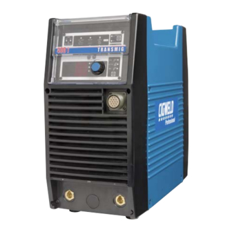
Page 23: Operation
TRANSMIG 400 i SECTION 4: OPERATION 4.01 Transmig 400 i Controls Art A-08355_AB Figure 4-1: Transmig 400 i Power Source 1. Control Knob: This control sets the selected weld Socket Function parameter, rotating it clockwise increases the parameter that is indicated on the digital meter. - Page 24 TRANSMIG 400 i 3. Positive Terminal: Welding current flows from the Power Source via heavy duty Dinse type terminal. It is essential, however, that the male plug is inserted and turned securely to achieve a sound electrical connection. 4. Negative Terminal: Welding current flows from the Power Source via heavy duty Dinse type terminal. It is essential, however, that the male plug is inserted and turned securely to achieve a sound electrical connection.
-
Page 25: Weld Process Selection
ARC CONTROL Adjusts percentage increase in welding current and is proportional to arc length (arc voltage). Table 4-3: Weld Process selection versus Weld Mode for Transmig 400 i 4.03 Weld Parameter Descriptions WELD (V): This parameter sets the MIG weld arc voltage in MIG mode. - Page 26 TRANSMIG 400 i ARC CONTROL This parameter operates in STICK mode only and is used to adjust percentage increase in welding current and is proportional to arc length (arc voltage). This control provides an adjustable amount of arc control (or dig). This feature can be particularly beneficial in providing the operator with the ability to compensate for variability in joint fit up in certain situations with particular electrodes, e.g.
-
Page 27: Front Panel Weld Parameter Descriptions
Weld Voltage (Volt) – Transmig 400 i memory. when lit parameter knob The Save/Load buttons sets the MIG voltage. must be depressed for 3 seconds to store settings. Table 4-4: Transmig 400 i Front Panel Parameter Description July 18, 2008... -
Page 28: Weld Parameters
TRANSMIG 400 i 4.05 Weld Parameters Weld Mode Weld Parameter Range Factory Incremental LIFT Parameter Setting Unit STICK WELD (V) 10.0 to 36.0V DC 17.0V 0.1V INDUCTANCE 0 to 100% HOT START 0 to 70A WELD (A) 5 to 400A DC... - Page 29 TRANSMIG 400 i • Control Knob For the selected weld parameter, rotating the knob clockwise increases the parameter. • Rotating the knob counter-clockwise decreases the parameter. • A selected weld parameter value can be adjusted at any time even while welding.
-
Page 30: Set-Up For Mmaw (Stick) And Gtaw (Tig)
CAUTION Remove any packaging material prior to use. Do not block the air vents at the front or rear or sides of the welding power source. Figure 4-4: Transmig 400 i MMAW/GTAW Set-up July 18, 2008... -
Page 31: Set-Up For Gmaw/Fcaw (Mig)
4.08 Set-up for GMAW/FCAW (MIG) MIG welding with the Transmig 400 i requires the integration of a constant voltage (CV) wire feeder. Shielding gas will also usually be required in most cases except for some flux cored welding operations (FCAW). When setting up for flux cored welding, contact the welding wire manufacturer for lead polarity recommendations. -
Page 32: Sequence Of Operation
Symbol descriptions. Art # A-08422 Figure 4-6: Transmig 400 i Front Panel 1. Contactor Function: Pressing this buttons enables Contactor functions. This function is operable in MIG mode only. It is used to enable the output such that a voltage sensing wirefeeder i.e. Transmig VS 212 can be connected. -
Page 33: Stick Welding
TRANSMIG 400 i 4.10 Stick Welding • Connect work lead to negative terminal. • Connect electrode lead to positive terminal. • Switch machine on. • Set weld current. • Set Contactor. • Connect remote control device if required. Use the Scroll Buttons to move to the parameter to be set. The LED will show which function is being adjusted on the weld sequence graph. -
Page 34: Save-Load Operation
TRANSMIG 400 i 4.13 Save-Load Operation A total number of 5 programs can be saved into the Transmig 400 i memory. SAVE the Current Weld Parameters into Memory • Press and HOLD the SAVE button for 3 seconds. Beep will sound and Digital Meter display will show a number 1. -
Page 35: Basic Welding Guide
TRANSMIG 400 i SECTION 5: BASIC WELDING GUIDE 5.01 Basic TIG Welding Guide 5.01.1 Electrode Polarity Connect the TIG torch to the - / TORCH terminal and the work lead to the + / WORK terminal for direct current straight polarity. Direct current straight polarity is the most widely used polarity for DC TIG welding. -
Page 36: Guide For Selecting Filler Wire Diameter
TRANSMIG 400 i 5.01.4 Guide for Selecting Filler Wire Diameter Filler Wire Diameter AC Current Range DC Current Range (Amps) (Amps) 1/16” (1.6 mm) 30 - 95 20 - 90 3/32” (2.4 mm) 125 - 160 65 - 115 1/8” (3.2 mm) -
Page 37: Welding Parameters For Steel
TRANSMIG 400 i 5.01.7 Welding Parameters for Steel Base Metal DC Current for DC Current for Tungsten Filler Rod Argon Gas Thickness Mild Steel Stainless Electrode Diameter Flow Rate Joint Type Steel Diameter (if required) Liters/min 35-45 20-30 Butt/Corner 0.040”... -
Page 38: Basic Stick Welding Guide
TRANSMIG 400 i Cast Iron 5.02 Basic STICK Welding Guide Most types of cast iron, except white iron, are 5.02.1 Electrode Polarity weldable. White iron, because of its extreme brittleness, generally cracks when attempts are Stick electrodes are generally connected to the made to weld it. -
Page 39: Basic Mig Welding Guide
The choice of electrode wire size in conjunction 5.03.1 Setting of the Power Source with shielding gas used depends on: The setting of the Transmig 400 i requires some • The position of welding practice by the operator, the welding Power •... - Page 40 TRANSMIG 400 i THIS PAGE LEFT INTENTIONALLY BLANK July 18, 2008...
-
Page 41: Service
TRANSMIG 400 i SECTION 6: SERVICE 6.01 Routine Maintenance The only routine maintenance required for the power supply is a thorough cleaning and inspection, with the frequency depending on the usage and the operating environment. WARNING Disconnect primary power at the source before opening the enclosure. Wait at least two minutes before opening the enclosure to allow the primary capacitors to discharge. -
Page 42: Maintenance Diagram
TRANSMIG 400 i 6.02 Maintenance Diagram Warning! Disconnect input power before maintaining. Maintain more often if used under severe conditions Each Use Visual check of torch Visual check of Consumable parts regulator and pressure Weekly Visually inspect the torch Visually inspect the body and consumables cables and leads. -
Page 43: Basic Troubleshooting
WARNING There are extremely dangerous voltages and power levels present inside this product. Do not attempt to open or repair unless you are an Accredited Cigweld Service Provider and you have had training in power measurements and troubleshooting techniques. If major complex subassemblies are faulty, then the Welding Power Source must be returned to an Accredited Cigweld Service Provider for repair. - Page 44 TRANSMIG 400 i Inconsistent Wire Feed Checking the following points can reduce wire-feeding problems: 1. Wire spool brake is too tight. Feed roller driven by motor in the cabinet will slip. 2. Wire spool brake is too loose. Wire spool can unwind and tangle.
-
Page 45: Mig Welding Problems
A Check all welding cable connections. B Low Primary Voltage. B Contact supply authority. C Faulty rectifier unit. C Have an accredited Cigweld Service Provider to test then replace the faulty component. Arc does not have The MIG torch has been connected... -
Page 46: Tig Welding Problems
TRANSMIG 400 i 6.06 TIG Welding Problems Weld quality is dependent on the selection of the correct consumables, maintenance of equipment and proper welding technique. Description Possible Cause Remedy 1 Excessive bead build-up or poor Welding current is too low... - Page 47 TRANSMIG 400 i Description Possible Cause Remedy 10 Arc flutters during TIG welding A Tungsten electrode is too A Select the right size large for the welding current electrode. Refer to Basic TIG Welding Guide B Absence of oxides in the...
-
Page 48: Stick Welding Problems
TRANSMIG 400 i 6.07 Stick Welding Problems Description Possible Cause Remedy 1 Gas pockets or voids in weld metal A Electrodes are damp A Dry electrodes before use (Porosity) B Welding current is too high B Reduce welding current C Surface impurities such as... - Page 49 TRANSMIG 400 i Description Possible Cause Remedy 4 Portions of the weld run do not A Small electrodes used on A Use larger electrodes and fuse to the surface of the metal or heavy cold plate preheat the plate edge of the joint...
- Page 50 TRANSMIG 400 i 6.07 Stick Welding Problems (con't) Description Possible Cause Remedy 5 Non-metallic particles are trapped A Non-metallic particles may A If bad undercut is in the weld metal (slag inclusion) be trapped in undercut from present, clean slag out...
-
Page 51: Power Source Problems
TRANSMIG 400 i 6.08 Power Source Problems Description Possible Cause Remedy 1 The welding arc cannot be A The Primary supply voltage A Switch ON the Primary established has not been switched ON supply voltage B The Welding Power Source... -
Page 52: Power Source Error Codes
TRANSMIG 400 i 6.09 Power Source Error Codes Description Possible Cause Remedy Remarks 1 E01 error code displayed The Welding Power Let Power Source Weld current ceases. Temperature sensor TH1 Source’s duty cycle cool down then keep Buzzer sounds (protects IGBTs) is has been exceeded. - Page 53 TRANSMIG 400 i Description Possible Cause Remedy Remarks 7 E14 error code displayed Mains supply Have an accredited Weld current available. Under mains supply voltage is less than Cigweld Service Buzzer sounds (input) voltage warning the nominal Provider or a intermittently.
-
Page 54: Voltage Reduction Device (Vrd)
In addition to the above tests and specifically in relation to the VRD fitted to this machine, the following periodic tests should also be conducted by an accredited Cigweld service agent. Description Required Parameters VRD Open Circuit Less than 20V;... -
Page 55: Appendix 1: Options And Accessories
TRANSMIG 400 i APPENDIX 1: OPTIONS AND ACCESSORIES Description Part No. Details 17 Series air cooled TIG torch 518710402 TIG torch with 4 metre cable & remote (suitable for TransTig 200Pi) current control 26 Series air cooled TIG torch 538720401 TIG torch with 4 metre cable &... -
Page 56: Appendix 2: Transmig 400 I Interconnect Diagram
TRANSMIG 400 i APPENDIX 2: TRANSMIG 400 i INTERCONNECT DIAGRAM PCB22 CE Filter TB13 TB10 L111 L112 Circuit Board TB14 TB11 [WK-5022] TB15 TB12 PCB1 Main PCB8 PCB10 1 2 3 4 5 Circuit Board IGBT Gate IGBT Gate L106... - Page 57 TRANSMIG 400 i PCB15 DIODE Snubber Circuit Board [WK-6131] PCB14 TRANS Board [WK-5594] 1 2 3 TB35 +Output Terminal HCT1 TB33 TB21 TB34 L110 TB30 TB16 TB16 1 2 3 4 5 Ground TB32 RY+15V PCB20 /RY_ON Filter Circuit Board...
- Page 58 TRANSMIG 400 i THIS PAGE LEFT INTENTIONALLY BLANK July 18, 2008...
-
Page 59: Cigweld Limited Warranty
“Purchaser” that its products will be free of defects in workmanship or material. Should any failure to conform to this warranty appear within the time period applicable to the CIGWELD products as stated below, CIGWELD shall, upon notification thereof and substantiation that the product has been stored, installed, operated, and maintained in accordance with CIGWELD’s specifications, instructions,... - Page 60 CIGWELD. 4. CIGWELD declares that, to the extent permitted by law, it hereby limits its liability in respect of the supply of goods which are not of a kind ordinarily acquired for personal, domestic or household use or consump- tion to any one or more of the following (the choice of which shall be at the option of CIGWELD).
- Page 61 Accredited Distributor of the equipment. Notwithstanding the foregoing, in no event shall the war- ranty period extend more than the time stated plus one year from the date CIGWELD delivered the product to the Accredited Distributor. Unless otherwise stated the warranty period includes parts and labour. CIGWELD reserves the right to request documented evidence of date of purchase.
-
Page 63: Global Customer Service Contact Information
48000 Rawang Selangor Darul Ehsan 800-426-1888 West Malaysia Fax: 800-535-0557 Telephone: 603+ 6092 2988 Email: sales@thermalarc.com Fax : 603+ 6092 1085 Thermadyne Canada Cigweld, Australia 2070 Wyecroft Road 71 Gower Street Oakville, Ontario Preston, Victoria Canada, L6L5V6 Australia, 3072 Telephone: (905)-827-1111... - Page 64 Asia Pacific Regional Headquarters 71 Gower Street Preston, Victoria, Australia, 3072 Telephone: +61 3 9474 7400 FAX: +61 3 9474 7488 Email: cigweldsales@cigweld.com.au www.cigweld.com.au...
Need help?
Do you have a question about the Transmig 400 i and is the answer not in the manual?
Questions and answers