Sign In
Upload
Download
Table of Contents
Contents
Add to my manuals
Delete from my manuals
Share
URL of this page:
HTML Link:
Bookmark this page
Add
Manual will be automatically added to "My Manuals"
Print this page
×
Bookmark added
×
Added to my manuals
Manuals
Brands
CIGWELD Manuals
Welding System
weldskill 100
Operating manual
CIGWELD weldskill 100 Operating Manual
Mig welding machine
Hide thumbs
1
2
3
Table Of Contents
4
5
6
7
8
9
10
11
12
13
14
15
16
17
18
19
20
21
22
23
24
25
26
27
28
29
30
31
32
33
34
35
36
37
38
39
40
41
42
43
44
45
46
47
48
49
50
51
52
53
54
55
56
57
58
59
60
page
of
60
Go
/
60
Contents
Table of Contents
Troubleshooting
Bookmarks
Table of Contents
Table of Contents
Section 1:Arc Welding Safety Instructions and Warnings
Arc Welding Hazards
Principal Safety Standards
Declaration of Conformity
Section 2:Introduction
How to Use this Manual
Equipment Identification
Receipt of Equipment
Symbol Chart
Description
User Responsibility
Transporting Methods
Packaged Items
Duty Cycle
Specifications
Options and Accessories
Section 3:Installation
Environment
Location
Ventilation
Mains Supply Voltage Requirements
Welding Face Shield Assembly
Face Shield Maintenance
Electromagnetic Compatibility
Using a Shielding Gas for (GMAW) Process
Attaching the Euro Style Connection Weldskill 150 MIG Torch
Polarity Changeover
Installing Minispool (100Mm Diameter) - Weldskill 100 MIG
Installing Minispool (100Mm Diameter) - Weldskill 135 and 150 MIG
Installing Handispool (200Mm Diameter) - Weldskill 135 and 150 MIG
Inserting Wire into the Wire Feed Mechanism
Drive Roller Pressure Adjustment
Changing Drive Roll
Setup for Weldskill 100 MIG
Setup for Weldskill 135 Mig with Gasless MIG Wire
Setup for Weldskill 135 MIG with Gas Shielded Mig Wire
Setup for Weldskill 150 Mig with Gasless MIG Wire
Setup for Weldskill 150 Mig with Gas Shielded MIG Wire
Section 4:Operation
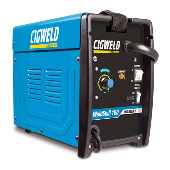
Weldskill 100 Mig Power Source Controls, Indicators and Features
Weldskill 135 Mig Power Source Controls, Indicators and Features
Weldskill 150 Mig Power Source Controls, Indicators and Features
Cigweld MIG Wire Selection Chart
Basic Welding Technique
Section 5:Service
Routine Maintenance & Inspection
Cleaning the Welding Power Source
Cleaning the Feed Rolls
Basic Troubleshooting
Welding Problems
Power Source Problems
Key Spare Parts
Appendix 1:100 Mig Circuit Diagram
Appendix 2:135 Mig Circuit Diagram
Appendix 3:150 Mig Circuit Diagram
Cigweld Limited Warranty
Warranty Schedule - MARCH 2008
Global Customer Service Contact Information
Advertisement
Quick Links
1
Setup for Weldskill 135 Mig with Gasless Mig Wire
2
Weldskill 135 Mig Power Source Controls, Indicators and Features
3
Key Spare Parts
4
Appendix 2:135 Mig Circuit Diagram
Download this manual
100
135
150
Operating Manual
weldskill
MiG weldinG Machine
Art # A-09010
Revision: AB
Issue Date: November 13, 2013
Operating Features:
100
135
150
AMP
AMP
AMP
AC
DC
®
240
V
DC
Manual No.: 0-5129
Table of
Contents
Previous
Page
Next
Page
1
2
3
4
5
Advertisement
Table of Contents
Need help?
Do you have a question about the weldskill 100 and is the answer not in the manual?
Ask a question
Questions and answers
Related Manuals for CIGWELD weldskill 100
Welding System CIGWELD TRANSarc 170i Operating Manual
Welding inverter (72 pages)
Welding System CIGWELD TRANSarc 170i Service Manual
Welding inverter (86 pages)
Welding System CIGWELD 170Oi Service Manual
Transtig welding inverter (92 pages)
Welding System CIGWELD Transmig 130 Twin Instruction Manual
(11 pages)
Welding System CIGWELD 170 HF Operating Manual
(48 pages)
Welding System CIGWELD Transmig 165ST Service Manual
Multi process welding inverter (126 pages)
Welding System CIGWELD WELDSKILL 180 Service Manual
Stick, tig (80 pages)
Welding System CIGWELD weldskill 150 Operating Manual
Mig welding machine (60 pages)
Welding System CIGWELD weldskill 135 Operating Manual
Mig welding machine (60 pages)
Welding System CIGWELD WeldSkill 155 Operating Manual
(88 pages)
Welding System CIGWELD WeldSkill 185 Operating Manual
(88 pages)
Welding System CIGWELD Transmig 185 Ultra Operating Manual
Auto set welding inverter (108 pages)
Welding System CIGWELD WeldSkill 120 Turbo Operation Manual
(30 pages)
Welding System CIGWELD 170Pi Operating Manual
Transtig welding inverter (72 pages)
Welding System CIGWELD 250i Transmig Service Manual
Multi process welding inverter (128 pages)
Welding System CIGWELD TRANSMIG 220 Operating Manual
(38 pages)
This manual is also suitable for:
Weldskill 150
Weldskill 135
Table of Contents
Save PDF
Print
Rename the bookmark
Delete bookmark?
Delete from my manuals?
Login
Sign In
OR
Sign in with Facebook
Sign in with Google
Upload manual
Upload from disk
Upload from URL


Need help?
Do you have a question about the weldskill 100 and is the answer not in the manual?
Questions and answers