
Related Manuals for CIGWELD 350i


Summary of Contents for CIGWELD 350i
-
Page 1: Service Manual
350i TRANSMIG 450i MulTI pRoceSS weldING INveRTeR 550i Art # A-11300 Service Manual Revision: AD Issue Date: May 7, 2013 Manual No.: 0-5204 Operating Features:... - Page 2 To locate your nearest distributor or Accredited service provider call +1300 654 674, or visit us on the web at www.cigweld.com.au This Service Manual has been designed to instruct you on the correct use and operation of your CIGWELD product.
- Page 3 Manufacturer assumes no liability for its use. Welding Power Supply Service Manual Number 0-5204 for: TRANSMIG 350i Plant Part Number W1005350 TRANSMIG 350i Power Source (packed) Part Number W1005352 TRANSMIG 450i Plant with 4RT wirefeeder Part Number W1005450 TRANSMIG 450i Pro Plant with VAF4 wirefeeder...
-
Page 4: Table Of Contents
Volt-Ampere Curves ..................3-6 SECTION 4: OPERATION ................... 4-1 4.01 Transmig 350i, 450i, 550i Power Source Controls, Indicators and Features ... 4-1 4.02 Shielding Gas Regulator Operating Instructions ........... 4-13 4.03 Setup for MIG (GMAW) Welding with Gas Shielded Mig Wire ...... 4-15 4.04... - Page 5 TABLE OF CONTENTS SECTION 6: TROUBLESHOOTING ................6-1 6.01 Basic Troubleshooting-Power Source Faults ........... 6-1 6.02 Main Circuit Description ................. 6-3 6.03 Test Equipment and Tools ................6-3 6.04 Case Removal ....................6-4 6.05 Visually Inspect ....................6-4 6.06 Preliminary DC Bus Measurement of the Main Inverter Board ......6-5 6.07 Preliminary Check of the Output Diodes IGBT's ..........
- Page 6 REPLACEMENT PARTS ................9-1 9.01 Power Source Replacement Parts ..............9-1 SECTION 10: OPTIONAL ACCESSORIES .................10-1 10.01 Optional Accessories ..................10-1 CIGWELD - LIMITED WARRANTY TERMS TERMS OF WARRANTY – January 2011 WARRANTY SCHEDULE – January 2011 GLOBAL CUSTOMER SERVICE CONTACT INFORMATION...
-
Page 7: Safety Instructions And Warnings
SAFETY INSTRUCTIONS AND WARNINGS TRANSMIG 350i, 450i, 550i SECTION 1: SAFETY INSTRUCTIONS AND WARNINGS WARNING PROTECT YOURSELF AND OTHERS FROM POSSIBLE SERIOUS INJURY OR DEATH. KEEP CHILDREN AWAY. PACEMAKER WEARERS KEEP AWAY UNTIL CONSULTING YOUR DOCTOR. DO NOT LOSE THESE INSTRUCTIONS. READ OPERATING/INSTRUCTION MANUAL BEFORE INSTALLING, OPERATING OR SERVICING THIS EQUIPMENT. - Page 8 TRANSMIG 350i, 450i, 550i SAFETY INSTRUCTIONS AND WARNINGS WARNING WARNING FUMES AND GASES can be hazardous to your health. FLYING SPARKS AND HOT METAL can cause injury. Welding produces fumes and gases. Breathing these Chipping and grinding cause flying metal. As welds fumes and gases can be hazardous to your health.
- Page 9 SAFETY INSTRUCTIONS AND WARNINGS TRANSMIG 350i, 450i, 550i Recommended Protective Filters for Electric Welding Minimum Shade Number of Approximate range of Weldi Description of Process Current in Amps Filter(s) Less than or equal to 100 100 to 200 Manual Metal Arc Welding covered...
-
Page 10: Principal Safety Standards
TRANSMIG 350i, 450i, 550i SAFETY INSTRUCTIONS AND WARNINGS 6. Reinstall panels or guards and close doors when servicing 1.02 Principal Safety Standards is finished and before starting engine. Safety in Welding and Cutting, ANSI Standard Z49.1, from American Welding Society, 550 N.W. LeJeune Rd., Miami, FL 33126. -
Page 11: Declaration Of Conformity
71 Gower St, Preston Victoria 3072 Australia Description of equipment: Welding Equipment: TRANSMIG 350i, 450i, 550i MULTI PROCESS INVERTER Power Source and associated accessories. * Serial numbers are unique with each individual piece of equipment and details description, parts used to manufacture a unit and date of manufacture. -
Page 12: Symbol Chart
TRANSMIG 350i, 450i, 550i SAFETY INSTRUCTIONS AND WARNINGS 1.04 Symbol Chart Note that only some of these symbols will appear on your model. Wire Feed Function Single Phase Wire Feed Towards Workpiece With Three Phase Output Voltage Off. Three Phase Static... -
Page 13: Servicing Hazards
SAFETY INSTRUCTIONS AND WARNINGS TRANSMIG 350i, 450i, 550i 1.05 Servicing Hazards WARNING FLYING METAL or DIRT can injure eyes. WARNING • Wear safety glasses with side shields or face shield during The symbols shown below are used throughout this servicing. manual to call attention to and identify possible haz- ards. -
Page 14: Emf Information
TRANSMIG 350i, 450i, 550i SAFETY INSTRUCTIONS AND WARNINGS • Keep hands, hair, loose clothing, and tools away from moving 1.06 EMF Information parts. • Reinstall doors, panels, covers, or guards when maintenance Considerations About Welding And The Effects Of Low Frequency is finished and before reconnecting input power. Electric And Magnetic Fields Welding current, as it flows through welding cables, will cause electromagnetic fields. -
Page 15: Introduction
Gives information regarding possible per- 2.04 Description sonal injury. Warnings will be enclosed in a box such as this. The Cigweld Transmig 350i, 450i and 550i are three phase multi process welding inverters that are capable of performing GMAW/FCAW (MIG), MMAW (Stick) CAUTION and GTAW (Lift TIG) welding processes. -
Page 16: User Responsibility
This equipment or any of its parts should not be altered from standard specification without prior written ap- Transmig 450i Pro Plant (Part No. W1005451) proval of CIGWELD. The user of this equipment shall • Transmig 450i Inverter Power Source have the sole responsibility for any malfunction which • Transmig VAF-4 wirefeeder with 8m interconnec-... -
Page 17: Safety And Installation
(MIG, STICK & TIG ) 100 125 150 175 200 225 250 275 300 325 350 375 400 425 450 475 500 525 550 Welding Current (AMPS) A-10626 Figure 3-1: Transmig 350i, 450i, 550i Duty Cycle Manual 0-5204 Safety and Installation... -
Page 18: Specifications
CIGWELD Pty, Ltd reserves the right to change the specifications or design of any of its products without prior notice. - Page 19 SAFETY AND INSTALLATION TRANSMIG 350i, 450i, 550i 3.03 Gouging Specifications (Transmig 550i only) Gouging is a process where a copper coated carbon electrode is used to rapidly remove material from the workpiece. The arc voltage is much higher during Gouging, than in Stick, or Mig welding. This means, that for the same output current, we have much higher arc volts during Gouging, and therefore much higher output power.
-
Page 20: Environment
TRANSMIG 350i, 450i, 550i SAFETY AND INSTALLATION • Precautions must be taken against the power 3.04 Environment source toppling over. The power source must be These units are designed for use in environments with located on a suitable horizontal surface in the increased hazard of electric shock as outlined in AS upright position when in use. -
Page 21: Electromagnetic Compatibility
SAFETY AND INSTALLATION TRANSMIG 350i, 450i, 550i 3.08 Electromagnetic Compatibility WARNING Extra precautions for Electromagnetic Compatibility may be required when this Welding Power Source is used in a domestic situation. A. Installation and Use - Users Responsibility The user is responsible for installing and using the welding equipment according to the manufacturer’s instructions. - Page 22 TRANSMIG 350i, 450i, 550i SAFETY AND INSTALLATION 2. Maintenance of Welding Equipment The welding equipment should be routinely maintained according to the manufacturer’s recommendations. All access and service doors and covers should be closed and properly fastened when the welding equipment is in operation. The welding equipment should not be modified in any way except for those changes and adjustments...
-
Page 23: Volt-Ampere Curves
Welding Current (amps) FORCE GTAW (Lift Tig) TRANSMIG 550i TRANSMIG 450i TRANSMIG 350i Welding Current (amps) GMAW (Mig) TRANSMIG 550i TRANSMIG 450i TRANSMIG 350i Welding Current (amps) A-10644 Figure 3-3: Transmig 350i, 450i, 550i Volt-Ampere Curves Manual 0-5204 Safety and Installation... - Page 24 TRANSMIG 350i, 450i, 550i SAFETY AND INSTALLATION Safety and Installation Manual 0-5204...
-
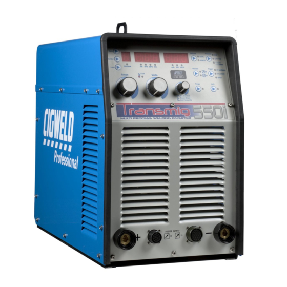
Page 25: Operation
OPERATION TRANSMIG 350i, 450i, 550i SECTION 4: OPERATION 4.01 Transmig 350i, 450i, 550i Power Source Controls, Indicators and Features A-10627 A-10628 Manual 0-5204 Operation... - Page 26 TRANSMIG 350i, 450i, 550i OPERATION A-10629 Figure 4-1: Power Source Controls, Indicators and Features 1. Amperage Control (Wirespeed) The amperage control knob adjusts the amount of welding current delivered by the power source. In MMAW (stick) and GTAW (Lift TIG) modes, the amperage control knob directly adjusts the power inverter to deliver the desired level of output current.
- Page 27 OPERATION TRANSMIG 350i, 450i, 550i 2. Voltage Control The voltage control knob adjusts the amount of welding voltage delivered by the power source. In MMAW (stick) and GTAW (Lift TIG) modes, the voltage control knob is inactive. In 10 PIN and 19 PIN GMAW/FCAW modes (MIG), the voltage knob directly adjusts the power inverter to deliver the desired level of output voltage.
- Page 28 TRANSMIG 350i, 450i, 550i OPERATION 6. Local / Remote Button The REMOTE button is used to select REMOTE or LOCAL mode of operation. The REMOTE button is used only when a remote control device (such as a TIG torch with remote current control, or a Wirefeeder) is fitted to the unit via the remote control socket (items 5 &...
- Page 29 The red VRD OFF light illuminates (green light is off) when the VRD is inactive. Under this condition the output voltage of the unit will be at welding potential which in some cases may exceed 35V DC. The VRD incorporated within the TRANSMIG 350i, 450i and 550i is fully standards compliant to AS 60974.1 / IEC 60974-1.
- Page 30 TRANSMIG 350i, 450i, 550i OPERATION 11. Thermal Overload Indicator Light (Fault) This welding power source is protected by a self resetting thermostat. The indicator will illuminate if the duty cycle of the power source has been exceeded. Should the thermal overload indicator illuminate the output of the power source will be disabled.
- Page 31 OPERATION TRANSMIG 350i, 450i, 550i NOTE The preview functionality provided on this power source is intended to act as a guide only. Some difference may be observed between preview values and actual welding values due to factors including the mode of welding, differences in consumables/gas mixtures, individual welding techniques and the transfer mode of the welding arc (ie dip versus spray transfer).
- Page 32 TRANSMIG 350i, 450i, 550i OPERATION 15. Advanced Features The TRANSMIG 350i, 450i and 550i have a series of Advanced features that allow the control of multiple parameters. These are accessed by pressing the AMPS and VOLTS knobs at the same time.
- Page 33 16. Fan as Needed The TRANSMIG 350i, 450i and 550i are fitted with a fan as needed feature. Fan as needed automatically switches the cooling fan off when it is not required. This has two main advantages; (1) to minimize power consumption, and (2) to minimise the amount of contaminants such as dust that are drawn into the power source.
- Page 34 TRANSMIG 350i, 450i, 550i OPERATION 20. 10 Pin Control Socket The 10 pin receptacle is used to connect a Wirefeeder or other suitable remote control device to the welding Power Source circuitry: To make connections, align keyway, insert plug, and rotate threaded collar fully clockwise. The socket...
- Page 35 OPERATION TRANSMIG 350i, 450i, 550i 21. 19 Pin Wirefeeder Control Socket The WIREFEEDER 19 pin receptacle is used to connect a Wirefeeder to the welding Power Source circuitry. To make connections, align keyway, insert plug, and rotate threaded collar fully clockwise. The socket information is included in the event the supplied cable is not suitable and it is necessary to wire a plug or cable to interface with the WIREFEEDER 19 pin receptacle.
- Page 36 Accredited Cigweld Service provider investigate the fault. 23. Restore Factory Default Settings The Transmig 350i, 450i and 550i can have Factory Default Settings Restored .This function is accessed by pressing the AMPS and INDUCTANCE knobs at the same time for two seconds (2s). The VOLTS and AMPS led's will flash 3 times to indicate a Factory Reset has been completed.
-
Page 37: Shielding Gas Regulator Operating Instructions
OPERATION TRANSMIG 350i, 450i, 550i 4.02 Shielding Gas Regulator Operating Instructions WARNING This equipment is designed for use with welding grade (Inert) shielding gases only. Shielding Gas Regulator Safety This regulator is designed to reduce and control high pressure gas from a cylinder or pipeline to the working pressure required for the equipment using it. - Page 38 TRANSMIG 350i, 450i, 550i OPERATION Installation 1. Remove cylinder valve plastic dust seal. Clean the cylinder valve outlet of impurities that may clog orifices and damage seats before connecting the regulator. Crack the valve (open then close) momentarily, pointing the outlet away from people and sources of ignition.
-
Page 39: Setup For Mig (Gmaw) Welding With Gas Shielded Mig Wire
OPERATION TRANSMIG 350i, 450i, 550i 2. To reduce flow rate, allow the welding grade shielding gas to discharge from regulator by opening the downstream valve. Bleed welding grade shielding gas into a well ventilated area and away from any ignition source. Turn adjusting screw counterclockwise, until the required flow rate is indicated on the gauge. - Page 40 TRANSMIG 350i, 450i, 550i OPERATION C. Fit the gas regulator and flowmeter to the gas cylinder then connect the gas hose from the rear of the Wirefeeder to the flowmeter outlet. D. Dual groove feed rollers are supplied as standard. Select the roller required with the chosen wire size marking facing outwards.
- Page 41 OPERATION TRANSMIG 350i, 450i, 550i Positive Welding Terminal (+) Negative Welding Terminal (-) 19 Pin Control Socket Work Lead Powered Wirefeeder (19 Pin) Mig Torch A-10639 Figure 4-7: Setup for Mig Welding with Gas Shielded Mig Wire Manual 0-5204 4-17...
-
Page 42: Setup For Mig (Gmaw) Welding With Gasless Mig Wire
TRANSMIG 350i, 450i, 550i OPERATION 4.04 Setup for MIG (GMAW) Welding with Gasless Mig Wire POWER SOURCE CONNECTIONS A. Remove all packaging materials. Do not block the air vents at the front or rear of the Power Source. B. Connect the work lead to the positive welding terminal (+). If in doubt, consult the electrode wire manufacturer. - Page 43 OPERATION TRANSMIG 350i, 450i, 550i WARNING DO NOT WEAR GLOVES WHILE THREADING THE WIRE OR CHANGING THE WIRE SPOOL. G. Lower the pressure levers and with the torch lead reasonably straight, feed the electrode wire through the torch. Fit the appropriate contact tip, eg a 0.9mm tip for 0.9mm wire.
-
Page 44: Setup For Tig (Gtaw) Welding With Gas Shielding
TRANSMIG 350i, 450i, 550i OPERATION 4.05 Setup for TIG (GTAW) Welding With Gas Shielding A. Remove all packaging materials. Do not block the air vents at the front or rear of the Power Source. B. Connect the work lead to the positive welding terminal (+).Welding current flows from the Power Source via heavy duty bayonet type terminals. -
Page 45: Setup For Stick (Mmaw) Welding
OPERATION TRANSMIG 350i, 450i, 550i 4.06 Setup for STICK (MMAW) Welding A. Remove all packaging materials. Do not block the air vents at the front or rear of the Power Source. B. Connect the Electrode Holder to the positive welding terminal (+). If in doubt, consult the electrode manufacturer. -
Page 46: Setup For Gouging (Transmig 550I Only)
TRANSMIG 350i, 450i, 550i OPERATION 4.07 Setup for GOUGING (Transmig 550i only) A. Remove all packaging materials. Do not block the air vents at the front or rear of the Power Source. B. Connect the Carbon Arc Gouging Torch to the positive welding terminal (+). If in doubt, consult the carbon electrode manufacturer. -
Page 47: Theory Of Operation
THEORY OF OPERATION TRANSMIG 350i, 450i, 550i SECTION 5: THEORY OF OPERATION 5.01 Inverter Design What does the word inverter mean? The term inverter refers to the ability to change DC power into AC. Inverter power supplies immediately rectify the incoming AC to DC, and then the transistors create a higher frequency AC. - Page 48 TRANSMIG 350i, 450i, 550i THEORY OF OPERATION Notes Theory of Operation Manual 0-5204...
-
Page 49: Troubleshooting
TROUBLESHOOTING TRANSMIG 350i, 450i, 550i SECTION 6: TROUBLESHOOTING 6.01 Basic Troubleshooting-Power Source Faults The following table is a guide for analysing problems and making repairs to the Power Source. Fault Possible Cause Remedy There is no weld The main Power Switch is OFF... - Page 50 TRANSMIG 350i, 450i, 550i TROUBLESHOOTING The following table is a guide for analysing problems and making repairs to the Power Source Fault Possible Cause Remedy 10 PIN Wirefeed motor Internal wiring fault Check continuity of internal operates when the wiring from 10 PIN connector...
-
Page 51: Main Circuit Description
TROUBLESHOOTING TRANSMIG 350i, 450i, 550i 6.02 Main Circuit Description Turn off power and disconnect mains supply plug from receptacle before working on the unit. Allow two minutes for capacitors to discharge after disconnection from mains supply voltage. The mains supply voltage is connected via a three pole switch / circuit breaker to the input rectifier through an EMC filter. -
Page 52: Case Removal
TRANSMIG 350i, 450i, 550i TROUBLESHOOTING 6.04 Case Removal Turn off power and disconnect mains supply plug from receptacle before working on the unit. Allow two minutes for capacitors to discharge after disconnection from mains supply voltage. If the problem cannot be solved by the basic (external) troubleshooting guide, the Power Source cover will have to be removed to allow the technician to analyse failures with a few common tools. -
Page 53: Preliminary Dc Bus Measurement Of The Main Inverter Board
TROUBLESHOOTING TRANSMIG 350i, 450i, 550i 6.06 Preliminary DC Bus Measurement of the Main Inverter Board Read and follow safety information in Section 6.02 before proceeding. And Check DC bus voltage has discharged to less than 5VDC before servicing. ENSURE THE MAINS SUPPLY PLUG IS DISCONNECTED FROM RECEPTACLE. -
Page 54: Preliminary Check Of The Output Diodes Igbt's
TRANSMIG 350i, 450i, 550i TROUBLESHOOTING 6.07 Preliminary Check of the Output Diodes IGBT's Read and follow safety information in Section 6.02 before proceeding. Art # A-11303 Output Diode Testing Multimeter Lead Placement Diode Voltage Output Diode 1 Positive meter lead to testpoint 3 0.2 –... - Page 55 TROUBLESHOOTING TRANSMIG 350i, 450i, 550i 11 12 Art # A-11304 14 15 IGBT Testing Multimeter Lead Placement Diode Voltage IGBT 1 Positive meter lead to testpoint 11 0.2 – 0.8 VDC Negative meter lead to testpoint 10 IGBT 2 Positive meter lead to testpoint 10 0.2 –...
-
Page 56: Check Main Input Rectifier
TRANSMIG 350i, 450i, 550i TROUBLESHOOTING 6.08 Check Main Input Rectifier Art # A-11305 Input Rectifier Testing Multimeter Lead Placement Diode Voltage AC1 to DC+ Positive meter lead to testpoint 16 0.2 – 0.8 VDC Negative meter lead to testpoint 1... -
Page 57: Dc Bus Voltage Measurement
TROUBLESHOOTING TRANSMIG 350i, 450i, 550i 6.09 DC Bus Voltage Measurement Apply voltage to the Power Source. There are extremely dangerous voltage and power levels present inside these Power Sources. Do not attempt to diagnose or repair unless you have had training in power electronics measurement and troubleshooting techniques. -
Page 58: Pcb Connectors
TRANSMIG 350i, 450i, 550i TROUBLESHOOTING 6.10 PCB Connectors Control PCB 1X13 1X12 1X11 1X10 1X9 1X8 Art # A-11306 1X1 Header Pin Pin function signal 0VAC 0VAC 0VAC 0VAC 34VAC 34VAC 34VAC 34VAC 34VAC 34VAC 34VAC 34VAC 0VAC 0VAC 26VAC... - Page 59 TROUBLESHOOTING TRANSMIG 350i, 450i, 550i 1X3 Header Pin Pin function signal Fan relay positive control input 15VDC Fan relay positive control input 0VDC Thermal switch 0VDC Thermal switch 0VDC Table 6-11: 1X3 Header pin function (fan relay & thermal switch)
- Page 60 TRANSMIG 350i, 450i, 550i TROUBLESHOOTING 1X11 Header Pin Pin function signal PWM control signal to driver board 0VDC 0VDC 15VDC 15VDC -15VDC -15VDC Current sensor signal 0VDC 0VDC Table 6-16: 1X11 Header pin function (connects to Hall Effect Current Sensor & driver board) )
- Page 61 TROUBLESHOOTING TRANSMIG 350i, 450i, 550i 3X2Header Pin Pin function signal +5VDC 5VDC Serial interface data line Serial interface data line Serial interface data line Serial interface data line Serial interface data line 0VDC 0VDC Table 6-20: 3X2 Header pin function (connects to 1X6 header on control PCB)
-
Page 62: Calibration
Table 6-24: 2X3 Header pin function (Connects to primary current transformer) 6.11 Calibration Calibration The Calibration Procedure is applicable for Transmig 350i, 450i and 550i. Calibration differences for each model are included in each calibration step as applicable. 1X13 1X12... - Page 63 Select REMOTE SWITCH to 10 PIN mode on the front panel. Set the Remote Voltage Control Knob so the Power Source Voltmeter reads 40.0V For TRANSMIG 350i and 450i adjust Remote Voltage Control Knob so the Power Source Voltmeter reads 30.0V Apply a load of approximately 350A ±50A (300A ±50A for a Transmig 450i, 250A ±50A for a Transmig 350i)
- Page 64 Select REMOTE SWITCH to 10 PIN mode on the front panel. Set the Power Source Amps Control Knob to maximum Set the Remote Amps Control Knob so the Power Source Ammeter reads 350A (250A for a Transmig 350i) Apply a load of 350A 30.0V (250A 30.0V for a Transmig 350i)
-
Page 65: Circuit Diagram
TROUBLESHOOTING TRANSMIG 350i, 450i, 550i 6.12 Circuit Diagram A-10647_AB Manual 0-5204 6-17 Troubleshooting... - Page 66 TRANSMIG 350i, 450i, 550i TROUBLESHOOTING Notes Troubleshooting 6-18 Manual 0-5204...
-
Page 67: Disassembly Procedure
DISASSEMBLY PROCEDURE TRANSMIG 350i, 450i, 550i SECTION 7: DISASSEMBLY PROCEDURE 7.01 Safety Precautions for Disassembly Read and follow safety information in Section 6.02 before proceeding. Unplug unit before beginning Disassembly procedure. Manual 0-5204 Disassembly Procedure... -
Page 68: Control Pcb1 Board Removal
TRANSMIG 350i, 450i, 550i DISASSEMBLY PROCEDURE 7.02 Control PCB1 Board Removal Read and follow safety information in Section 6.02 before proceeding with disassembly Remove case (refer to 6.04) before remove control board. 1. M4 Screw. Remove 6 screws from Control panel. -
Page 69: Control Pcb2 Board Removal
DISASSEMBLY PROCEDURE TRANSMIG 350i, 450i, 550i 7.03 Control PCB2 Board Removal Read and follow safety information in Section 6.02 before proceeding with disassembly 1. M4 Screw. Remove 4 screws from Control panel. 2 Disconnect 2×1 harness from 2×1 connector. 3. Disconnect 2×2 harness from 2×2 connector. -
Page 70: Auxiliary Transformer 1 Removal
TRANSMIG 350i, 450i, 550i DISASSEMBLY PROCEDURE 7.04 Auxiliary Transformer 1 Removal Read and follow safety information in Section 6.02 before proceeding with disassembly 1. Remove 4 screws for transformer 1. Art # A-11311 Disassembly Procedure Manual 0-5204... -
Page 71: Auxiliary Transformer 2 Removal
DISASSEMBLY PROCEDURE TRANSMIG 350i, 450i, 550i 7.05 Auxiliary Transformer 2 Removal Read and follow safety information in Section 6.02 before proceeding with disassembly 1. Remove 2 screws on one side 2. Remove 2 screws on the other side. Art # A-11312... -
Page 72: Input Filter Removal
TRANSMIG 350i, 450i, 550i DISASSEMBLY PROCEDURE 7.06 Input Filter Removal Read and follow safety information in Section 6.02 before proceeding with disassembly 1. Loosen 6 screws. 2. Pull out cord. 3. Remove 4 screws. Art # A-11313 Disassembly Procedure Manual 0-5204... -
Page 73: Front Panel Removal
DISASSEMBLY PROCEDURE TRANSMIG 350i, 450i, 550i 7.07 Front Panel Removal Read and follow safety information in Section 6.02 before proceeding with disassembly 1. Remove 6 screws on front panel. 2. Remove 4 screws and remove 10 pin socket. 3. Remove 4 screws and remove 19 pin socket. -
Page 74: Front Panel (Operator Interface) Circuit Board Pcb Removal
TRANSMIG 350i, 450i, 550i DISASSEMBLY PROCEDURE 7.08 Front Panel (Operator Interface) Circuit Board PCB Removal Read and follow safety information in Section 6.02 before proceeding with disassembly 1. Remove two knobs with an allen key. 2. Remove screw with a flat head screwdriver. -
Page 75: Rear Panel Removal
DISASSEMBLY PROCEDURE TRANSMIG 350i, 450i, 550i 7.09 Rear Panel Removal Read and follow safety information in Section 6.02 before proceeding with disassembly 1. Remove 5 screws on rear panel . 2. Remove 4 screws for 4 over load protectors . -
Page 76: Power Switch S1, Fan And Power Cord Removal
TRANSMIG 350i, 450i, 550i DISASSEMBLY PROCEDURE 7.10 Power Switch S1, Fan and Power Cord Removal Read and follow safety information in Section 6.02 before proceeding with disassembly 1. Remove 2 screws . 2. Remove 3 input power cable. 3. Remove 3 power cable for the filter. -
Page 77: Main Power Inverter Removal
DISASSEMBLY PROCEDURE TRANSMIG 350i, 450i, 550i 7.11 Main Power Inverter Removal Read and follow safety information in Section 6.02 before proceeding with disassembly 1. Remove 3 wire screws. 2. Remove 2 wire screws. 3. Remove 6 board screws. 4. Remove 4 wire screws. - Page 78 TRANSMIG 350i, 450i, 550i DISASSEMBLY PROCEDURE Notes Disassembly Procedure 7-12 Manual 0-5204...
-
Page 79: Assembly Procedures
ASSEMBLY PROCEDURE TRANSMIG 350i, 450i, 550i SECTION 8: ASSEMBLY PROCEDURES 8.01 Installing Main Power Inverter 1. Install board screws. 2. Install wires screws. 3. Install capacitance screws. Art # A-11319 Manual 0-5204 Assembly Procedures... -
Page 80: Power Switch S1, Fan And Power Cord
TRANSMIG 350i, 450i, 550i ASSEMBLY PROCEDURES 8.02 Power Switch S1, Fan and Power Cord 1. Reinstall wires. 2. Reinstall wire. 3. Reinstall 2 screws. 4. Reinstall 6 fan screws on rear panel 5. Reinstall power cord screw. 6. Reinstall ground wire screw. -
Page 81: Installing Rear Panel
ASSEMBLY PROCEDURE TRANSMIG 350i, 450i, 550i 8.03 Installing Rear Panel 1. Reinstall 5 rear panel screws. 2. Reinstall over load protector and screw up 4 screws. Art # A-11321 Manual 0-5204 Assembly Procedures... -
Page 82: Installing Front Panel (Operator Interface) Circuit Board Pcb
TRANSMIG 350i, 450i, 550i ASSEMBLY PROCEDURES 8.04 Installing Front Panel (Operator Interface) Circuit Board PCB 1. Reinstall 10 PCB plastic screws. 2. Reinstall harnesses into corresponding connectors. 3. Reinstall 2 knobs. Reinstall screws with an allen key. 4. Reinstall small knob. Reinstall the screw with a flat head screwdriver. -
Page 83: Installing Front Panel
ASSEMBLY PROCEDURE TRANSMIG 350i, 450i, 550i 8.05 Installing Front Panel 1. Reinstall positive output terminal bolts and tighten it. 2. Reinstall negative output terminal bolts and tighten it. 3. Reinstall 10 pin socket and tighten 4 screws. 4. Reinstall 19 pin socket and tighten 4 screws. -
Page 84: Installing Input Filter
TRANSMIG 350i, 450i, 550i ASSEMBLY PROCEDURES 8.06 Installing Input Filter 1. Install 4 screws. 2. Install wires. 3. Tighten 6 screws. Art # A-11324 8.07 Installing Auxiliary Transformer 1 1. Install 4 screws of the Transformer. Art # A-11325 Assembly Procedures... -
Page 85: Installing Auxiliary Transformer 2
ASSEMBLY PROCEDURE TRANSMIG 350i, 450i, 550i 8.08 Installing Auxiliary Transformer 2 1. Install 2 screws on each side 2. Insstall 2 screws on the other side. Art # A-11326 Manual 0-5204 Assembly Procedures... -
Page 86: Installing Control Pcb2
TRANSMIG 350i, 450i, 550i ASSEMBLY PROCEDURES 8.09 Installing Control PCB2 1. Reinstall 4 screws. 2. Replug harness into 2×1 conector. 3. Replug harness into 2×2 conector. 4. Replug harness into 2×3 conector. Art # A-11310 Assembly Procedures Manual 0-5204... -
Page 87: Installing Control Pcb1
ASSEMBLY PROCEDURE TRANSMIG 350i, 450i, 550i 8.10 Installing Control PCB1 1. Reinstall 6 screws. 2. Replug harness into1×1 connector. 3. Replug harness into1×2 connector 4. Replug harness into1×3 connector 5. Replug harness into1×4 connector 6. Replug harness into1×5 connector 7. Replug harness into1×6 connector 8. -
Page 88: Installing Case
TRANSMIG 350i, 450i, 550i ASSEMBLY PROCEDURES 8.11 Installing Case 1. ReInstall 22 screws on side panel of welder. 2. Reinstall 6 screws on top panel. Assembly Procedures 8-10 Manual 0-5204... -
Page 89: Power Source Replacement Parts
Diode, Welding (all models) W7005215 Inverter transformer 550i W7005216 Inverter transformer 450i W7005217 Inverter transformer 350i Power Source Part No. W1005352 W7005230 Inverter transformer 350i Power Source Part No. W1005359 W7005218 Inductor 550i (all models) Table 9-1 Key Spare Parts... - Page 90 W7005219 Sensor, Hall Effect (all models) W7005201 PCB, IGBT driver (all models) W7005203 PCB, IGBT snubber (all models) except 350i Power Source Part No. W1005359 W7005229 PCB, IGBT snubber 350i Power Source Part No. W1005359 W7005204 PCB, current transformer (all models) except 350i Power Source Part No.
-
Page 91: Optional Accessories
TRANSMIG VA4000 wirefeeder, 19 pin, 110VAC 706965 TRANSMIG VAF-4 wirefeeder, 19 pin, 110VAC WSPLIER MIG Pliers 646265 Weld measurement gauge W7005358 10 Pin Control Plug 7977877 19 Pin Control Plug Table 10-1: Transmig 350i, 450i, 550i Optional Accessories Manual 0-5204 10-1 Accessories... - Page 92 TRANSMIG 350i, 450i, 550i OPTIONS AND ACCESSORIES Notes Accessories 10-2 Manual 0-5204...
- Page 93 WELD whether arising out of contract, negligence, strict tort, or under any warranty, or otherwise, shall not, except as expressly provided herein, exceed the price of the goods upon which such liability is based. No employee, agent, or representative of CIGWELD is authorized to change this warranty in any way or grant any other warranty.
- Page 94 CIGWELD. 4. CIGWELD declares that, to the extent permitted by law, it hereby limits its liability in respect of the supply of goods which are not of a kind ordinarily acquired for personal, domestic or household use or consumption to any one or more of the following (the choice of which shall be at the option of CIGWELD).
- Page 95 Accredited Distributor of the equipment. Notwithstanding the foregoing, in no event shall the warranty period extend more than the time stated plus one year from the date CIGWELD delivered the product to the Accredited Distributor. Unless otherwise stated the warranty period includes parts and labour. CIGWELD reserves the right to request documented evidence of date of purchase.
-
Page 97: Global Customer Service Contact Information
GLOBAL CUSTOMER SERVICE CONTACT INFORMATION Victor Technologies, China Cigweld, Australia 71 Gower Street No 100 Lao Hongjing Rd Preston, Victoria Minhang District Shanghai, PR, 200235 Australia, 3072 Telephone: 61-3-9474-7400 Telephone: 86-21-64072626 Fax: 86-21-64483032 Fax: 61-3-9474-7391 Email: cigweldsales@cigweld.com.au Victor Technologies Asia Sdn Bhd... - Page 98 Asia Pacific Regional Headquarters 71 Gower Street Preston, Victoria, Australia, 3072 Telephone: +61 3 9474 7400 FAX: +61 3 9474 7391 Email: enquiries@cigweld.com.au www.cigweld.com.au...
Need help?
Do you have a question about the 350i and is the answer not in the manual?
Questions and answers