
Related Manuals for Life Fitness SM80

Summary of Contents for Life Fitness SM80
- Page 1 8 STACK MULTI-JUNGLE (SM80) WITH HIGH & LOW PULLEYS UNPACKING AND ASSEMBLY INSTRUCTIONS M051-K50-B116...
-
Page 2: Assembly Time
SM80 Unpacking & Assembly Instructions The SM80 comes partially assembled. Follow the steps below to complete the assembly. WARNING: COMPONENTS OF THE SM80 ARE LARGE AND HEAVY. USE CAUTION WHEN ASSEMBLING THIS MACHINE. MATERIALS AND TOOLS REQUIRED FOR ASSEMBLY 1/2”, 3/8”, 5/8” & 9/16”... - Page 3 3. Remove the items in the parts boxes. These items are shown in Figure 1. A. Remove the bolts bag. B. Remove the parts shown below. Parts that are used to build the SM80 are described in the section HARDWARE at the end of these instructions.
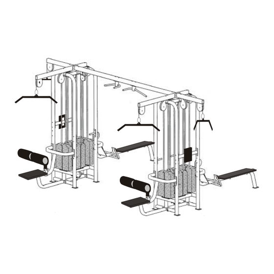
- Page 4 SM80 Unpacking & Assembly Instructions ASSEMBLY Figure 2 shows an assembled SM80. Figure 2. SM80 main components (seats and cables removed for clarity). 1. Cubes (2) 2. Low row bench (2) 3. Lat bench (2) 4. Connecting beam (1) 1. Place the two weight “cubes” in their “final resting spots.” The cubes will be approximately 11’4”...
- Page 5 SM80 Unpacking & Assembly Instructions Figure 3. Set the weight stack cubes. 2. Bolt on the teardrop pulleys above the benches (see Figure 4) on both cubes using two 3/8” x 2-3/4” hex head bolts (used to bolt the cross beam to the cross members and the adjustable pulley tops to the top beams).
- Page 6 SM80 Unpacking & Assembly Instructions Figure 4. Bolt on the teardrop pulleys. Figure 5. Configuration for 6” bolts.
- Page 7 Figure 7). Use the hardware configuration shown. You will need to remove the pulleys from the teardrop pulley assemblies to gain clearance for the socket wrench extension. Leave the pulleys out of the housings until the cables have been installed. SM80 Unpacking & Assembly Instructions 7/16” x 6” (8)- mount on tops...
- Page 8 SM80 Unpacking & Assembly Instructions Figure 8. Mount rubber bumpers and the weight stacks. 5. Install the weight stacks. To do this: A. Using a 9/16” socket and combination wrench, remove the tricep back rest bolts (see Figure 9). B. Using a 9/16” socket and combination wrench, unbolt the top plate and remove the guide rods (see Figure 9).
- Page 9 Figure 11 using a 9/16” socket and combination wrench and the 3” bolts (with cap washers) that were previously inserted. Figure 11. Bolt on the top plate. SM80 Unpacking & Assembly Instructions D. Flip over the weight stack onto piano dolly.
- Page 10 SM80 Unpacking & Assembly Instructions 6. Bolt the floating pulleys into the 190 lb weight stacks used for the crossovers using a 7/8” combination wrench. You will need to remove the pulley from the housing to thread the plug into the weight stack bayonet. Make sure the 9/16” jam nut is threaded 1-5/8”...
- Page 11 Use a pinch bar to align the seat frame holes to the cubes 3/8 x 3” Figure 13. Mount the benches to the frame. Figure 14. Bolt the benches to the frame. SM80 Unpacking & Assembly Instructions 3/8 x 2-3/4”...
-
Page 12: Installing The Cables
SM80 Unpacking & Assembly Instructions INSTALLING THE CABLES The SM80 uses eight cables. There are three different types of cable used on the SM80. They are: 1. Crossover cables (ball end cables) (2). 2. Low row cable (the long cables) (2). - Page 13 Once you’ve removed the pulleys as described previously, route the two crossover cables as shown in Figure 16. Figure 16. Crossover cable routing. LOW ROW CABLE ROUTING Route the low row cables as shown in Figure 17. SM80 Unpacking & Assembly Instructions...
- Page 14 SM80 Unpacking & Assembly Instructions Figure 17. Low row cable routing.
- Page 15 Figure 18. Screw the cable into the weight stack. LAT PULLDOWN CABLE ROUTING Route the lat pulldown cable as shown in Figure 19. Screw the cable into the weight stack as shown previously in Figure 18. Figure 19. Lat pulldown cable routing. SM80 Unpacking & Assembly Instructions...
- Page 16 SM80 Unpacking & Assembly Instructions TRICEP PUSHDOWN CABLE ROUTING Route the tricep pushdown cable as shown in Figure 20. Screw the cable into the weight stack as shown previously in Figure 18. Figure 20. Tricep pushdown cable routing.
- Page 17 SM80 Unpacking & Assembly Instructions HARDWARE ½ ½ ½ ½ ½ ½ Hardware Figure 1. Assembly Parts.
- Page 18 SM80 Unpacking & Assembly Instructions The parts shown in Hardware Figure 1 are used to assemble the SM80. They are: A. 7/16” x 6” hex head bolt (used to bolt the tricep top beams, lat top beams, and connecting beam to the tops of the cubes) B.
- Page 19 SM80 Unpacking & Assembly Instructions Hardware Figure 3. Cables. N. Lat pulldown cables (same as tricep cable) (2) P. Tricep cable (same as lat pulldown cables) (2) Q. Low row cables (long cables) (2) R. Crossover cables (ball end) (2)
- Page 20 SM80 Unpacking & Assembly Instructions S. Teardrop pulleys (bolt on above lat and seated row benches) (4) T. 56” Lat tops (bolt to top of cells with pulleys above lat benches) (2) U. 29” Tricep top (bolt on to 56” lat top bar) (2)
- Page 21 SM80 Unpacking & Assembly Instructions Hardware Figure 5. Weight stack rubber bumpers. W. Weight stack rubber bumpers (inserted under weight stacks) Hardware Figure 6. Floating pulleys. X. Floating pulleys (bolt to 190 lb cable crossover weight stacks)
-
Page 22: Parts List
SM80 Unpacking & Assembly Instructions PARTS LIST Part # Main components Cables, caps & nuts 0017-00103-0234 0017-00101-1408 0017-00101-1408 0017-00101-1422 0017-00101-1561 6” bolt hardware 0017-00101-1561 0017-00104-0363 0017-00104-0366 0017-00103-0233 2-3/4” & 3” bolt hardware 0017-00101-1422 0017-00101-1408 0017-00042-0969 0017-00104-0313 0017-00104-0368 0017-00103-0217 Pulleys and bumpers... - Page 23 Pulley hardware (installed) 0017-00101-1413 0017-00104-0368 0017-00103-0217 Floating pulley hardware (installed) 0017-00101-1413 0017-00104-0313 0017-00103-0217 SM80 Unpacking & Assembly Instructions 1-3/4” Bolt Cap washer 3/8” Nyloc nut 1-3/4” Bolt Flat washer 3/8” Nyloc nut...
Need help?
Do you have a question about the SM80 and is the answer not in the manual?
Questions and answers