Table of Contents
Advertisement
Quick Links
Download this manual
See also:
User Manual
Advertisement
Table of Contents

Subscribe to Our Youtube Channel
Related Manuals for Matrix JOHNNY G KRANKCYCLE


Summary of Contents for Matrix JOHNNY G KRANKCYCLE
-
Page 2: Table Of Contents
ABLE OF ONTENTS CHAPTER 1: IMPORTANT SAFETY INSTRUCTIONS PAGES Read and Save These Instructions..................Proper Usage ......................... Setting up the Krankcycle ..................® CHAPTER 2: KRANKCYCLE SPECIFICATIONS, PARTS AND ASSEMBLY GUIDES Specifications ......................... Required Parts, Fasteners and Tools ................. Assembly Steps ......................CHAPTER 3: GETTING TO KNOW THE Krankcycle Diagram ......................... -
Page 3: Read And Save These Instructions
1.1 READ AND SAVE THESE INSTRUCTIONS !WARNING! It is the sole responsibility of the purchaser of Matrix Fitness products to To reduce the risk of serious injury, read the following important precautions instruct all individuals, whether they are the end user or supervising and information before operating the Krankcycle. -
Page 4: Specifications
2.1 JOHNNY G KRANKCYCLE BY MATRIX SPECIFICATIONS The Johnny G Krankcycle by Matrix is designed according to EN957-5 standards as a Class S subcategory C product for professional and / or com- mercial use. Such training equipment is intended for use in training areas of commercial facilities such as Fitness Clubs or Sport Associations, where access and control is regulated by the person who has legal responsibility. -
Page 5: Required Parts, Fasteners And Tools
CHAPTER 2: K ranKcycle pecifications arts and ssembly teps 2.2 REQUIRED PARTS, FASTENERS & TOOLS (NOT INCLUDED) Part Name: Outline: Dimensions: Quantity: Bag Color: Flat Washer Black Socket Head Cap Screw M10 x 25mm Black Phillips Head Screw M4 x 8mm Socket Head Cap Screw M5 x 20mm Allen Key Wrench... -
Page 6: Assembly Steps
CHAPTER 2: K ranKcycle pecifications arts and ssembly teps 2.3 ASSEMBLY STEPS ATTENTION • Prior to assembling the Krankcycle, unpack all of the contents of the box and make sure that all necessary components are present. Review the contents of the hardware package for completeness. Contact your local distributor or go to www.matrixfitness.com to report any missing items. STEP 1 STEP 2 DRIVE FRAME... - Page 7 CHAPTER 2: K ranKcycle pecifications arts and ssembly teps 2.3 ASSEMBLY STEPS STEP 3 STEP 4 Place SMALL BASEPLATE FRONT COVER and LARGE MAIN BASE PLATE on metal Secure BASE PLATE to BASE FRAME from step 3 with item 3-PHILLIPS HEAD frame.
- Page 8 CHAPTER 2: K ranKcycle pecifications arts and ssembly teps 2.3 ASSEMBLY STEPS STEP 5 STEP 6 Attach LEFT HANDLE to LEFT CRANK ARM and RIGHT HANDLE to RIGHT Secure HANDLES tightly to CRANK ARMS using a 15mm WRENCH. CRANK ARM. Please note the LEFT HANDLE has a left hand thread.
- Page 9 CHAPTER 2: K ranKcycle pecifications arts and ssembly teps 2.3 ASSEMBLY STEPS STEP 7 STEP 8 Attach WATER BOTTLE CAGE to CENTER UPRIGHT FRAME with 4mm ALLEN KEY Attach SEAT to UPRIGHT FRAME by securely placing SEAT HOOKS around WRENCH using item 4-SOCKET HEAD CAP SCREWS. PROTRUDING PIN.*** !WARNING! Make sure SEAT HOOKS are fully engaged around protruding...
-
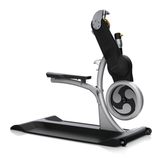
Page 10: Chapter 3: Getting To Know The Krankcycle
CHAPTER 3: G ettinG ranKcycle Upper Drive Resistance Knob (crank axis) Height Adjustment Lever RIGHT Crank Arm Rotation Lever Lower Drive Flywheel Rolling Wheel Leveling Foot... -
Page 11: Chapter 4: Using The Krankcycle
CHAPTER 4: u sinG ranKcycle 4.1 PROPER SET UP The Krankcycle was designed explicitly for upper body and cardiovascular training. To maximize exercise effectiveness and comfort, the Krankcycle should be adjusted for each user and exercise position. The instructions below describe one approach to adjusting the cycle to ensure optimal user comfort and ideal body positioning: you may choose to adjust the cycle differently. -
Page 12: How To Operate
CHAPTER 4: u sinG ranKcycle CHANGE CRANK ARM DIRECTION 4.2 HOW TO OPERATE To bring cranking direction from forward or reverse, bring crank arms to top position, release rotation level, turn drive frame 180º and lock rotation lever !WARNING! Do not operate this cycle with 2 people, equipment is back into place (toward the word lock) and pivot crank arms back toward user. -
Page 13: Serial Number Location
5.1 JOHNNY G KRANKCYCLE by MATRIX !WARNING! Regular maintenance must be performed on the Krankcycle for optimal performance and longevity. Please read and follow all instructions below. If the cycle is not maintained as described, components may wear excessively and the cycle may become damaged. -
Page 14: Bi-Yearly (6 Month) Maintenance
CHAPTER 6: P reventative aintenance b. Check brake pad setting by first turning the resistance knob toward the b. Thoroughly wipe down around all internal components and look for signs “-“ sign as far as it will go (minimum braking effect). The brake pad should of excessive wear or damage. - Page 15 CHAPTER 6: P reventative aintenance UPPER DRIVE ARM EXHIBITS EXCESSIVE SIDE-TO-SIDE PLAY To complete adjustment tighten upper set screw and replace rotation lever and cap. Check if rotation lever is fully engaged (A). If so, follow next steps. ROTATION LEVER POPS UP WHILE THE CYCLE IS IN USE If the rotation lever loosens or pops up while the cycle is in use, per- form the maintenance suggestions for “UPPER DRIVE ARM EXHIBITS EXCESSIVE SIDE-TO-SIDE PLAY”...
- Page 16 CHAPTER 6: P reventative aintenance Loosen (do not remove) the brake cable screw (C) and turn the resistance knob toward the “-“ sign as far as it will go (minimum braking effect). Then turn the knob toward the “+” sign 1 full revolution. Make sure the brake pad is pressed against the flywheel, and then secure the brake cable under the brake cable screw (C).
- Page 17 If the chain needs to be CYCLE DIFFICULT TO PUSH WHEN MOVING replaced,contact MATRIX customer service. The front rolling wheels may need lubrication. Remove both wheels by Remove the RIGHT crank arm by removing 5 socket head cap screws with a unscrewing the nut and bolt.
- Page 20 M AT RIX F IT NESS | 1 600 L A ND M ARK D RIVE COT TAGE GROV E, W I 53527 USA To l l Fre e m a t r i x f i t n e ss . co m Fa x 86 6 .693.48 63 608.
Need help?
Do you have a question about the JOHNNY G KRANKCYCLE and is the answer not in the manual?
Questions and answers