Table of Contents
Advertisement
Quick Links
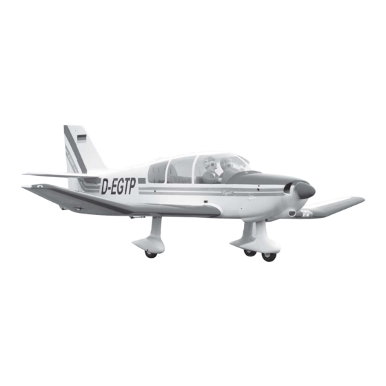
SPECIFICATION
Wingspan :
Length
Weight
Parts listing required (not included)
Radio
Servo
Engine
Instruction Manual book
2,200 mm
:
1,760 mm
:
7.4 kg
:
07 channes.
:
09 Standard high torque servos.
:
O.S GT 22-33 CC Gas.
86.61 in.
69.29 in.
16.28 Lbs.
Made in Vietnam.
Item code:BH129
Advertisement
Table of Contents

Related Manuals for Black Horse Model BH129


Summary of Contents for Black Horse Model BH129
- Page 1 Instruction Manual book Item code:BH129 SPECIFICATION Wingspan : 2,200 mm 86.61 in. Length 1,760 mm 69.29 in. Weight 7.4 kg 16.28 Lbs. Parts listing required (not included) ...
- Page 2 JODEL ROBIN DR400 - Item code: BH129 . INSTRUCTION MANUAL This instruction manual is designed to help you build a great flying aeroplane. Please read this manual thoroughly before starting assembly of your Jodel Robin DR400. Use the parts listing below to identify all parts.
-
Page 3: Safety Precaution
JODEL ROBIN DR400 - Item code: BH129 . INSTRUCTION MANUAL Caution: this model is not a toy! If you are a beginner to this type of powered model, please ask an experienced model flyer for help and support. If you attempt to operate the model without knowing what you are doing you could easily injure yourself or somebody else. - Page 4 JODEL ROBIN DR400 - Item code: BH129 . INSTRUCTION MANUAL REPLACEMENT LARGE PARTS A.Cowling. D.Horizontal stabilizer. F2. Aluminium tube horizontal stabilizer. E. Rudder B.Wing panel(B1&B2). G. Decal sheets. C.Fuselage. F1. Aluminium tube wing. K.Pilot REPLACEMENT SMALL PARTS 4x15mm. 4x15mm. 3x20mm.
-
Page 5: Installing The Aileron Servos
JODEL ROBIN DR400 - Item code: BH129 . INSTRUCTION MANUAL I. AILERON. Servo tray. 1.INSTALLING THE AILERON SERVOS. 1) Install the rubber grommets and brass eyelets onto the aileron servos. Remove covering. Servo tray. Bottom side Top side Secure. -
Page 6: Installing The Aileron Linkages
JODEL ROBIN DR400 - Item code: BH129 . INSTRUCTION MANUAL 2x10mm. A+B Epoxy PLUS glue Secure Control horn of the aileron. Repeat the procedure for the other wing half. INSTALLING THE AILERON CONTROL HORN. Repeat the procedure for the other wing... - Page 7 JODEL ROBIN DR400 - Item code: BH129 . INSTRUCTION MANUAL Thread Secure. Electric wire Repeat the procedure for the other wing half. II. FLAP SERVO. 2x10mm. 1.INSTALLING THE FLAP SERVOS. Secure. Flap...
- Page 8 JODEL ROBIN DR400 - Item code: BH129 . INSTRUCTION MANUAL 2.INSTALLING THE FLAP CONTROL HORN. Flap control horn A+B Epoxy PLUS glue Secure. Flap control 4x12mm horn. 3. INSTALLING THE FLAP LINKAGES. Installing the flap linkages as pictures below. M3 lock nut...
- Page 9 JODEL ROBIN DR400 - Item code: BH129 . INSTRUCTION MANUAL Secure 4x15mm 4x8mm Flap Repeat the procedure for the other wing half. MAIN GEAR INSTALATION. PARTS REQUIRED 4x15mm 4x15mm 4x8mm 5x40mm 4x 15mm...
- Page 10 JODEL ROBIN DR400 - Item code: BH129 . INSTRUCTION MANUAL Secure. Secure. Drill a hole hole 7mm 5x 40mm 4x 8mm...
-
Page 11: Installing The Engine Mount
JODEL ROBIN DR400 - Item code: BH129 . INSTRUCTION MANUAL INSTALLING THE ENGINE MOUNT. See pictures below: Secure. 5x 70mm Secure Drill a hole 5mm diameter Bottom side. Secure. Repeat the procedure for the other gear. -
Page 12: Installing The Throttle Cable
JODEL ROBIN DR400 - Item code: BH129 . INSTRUCTION MANUAL Cut off the excess cable. Front view. INSTALLING THE THROTTLE CABLE. 1. Install one adjustable metal connector through the third hole out from the center of one servo arm, enlarge the hole in the servo arm using a 2mm drill bit to accommodate the servo connector. - Page 13 JODEL ROBIN DR400 - Item code: BH129 . INSTRUCTION MANUAL 8) Feed three lines through the fuel tank When the stopper assembly is installed in the tank, the top of the vent tube should rest just compartment and through the pre-drilled hole below the top surface of the tank.
- Page 14 JODEL ROBIN DR400 - Item code: BH129 . INSTRUCTION MANUAL pushrod choke. pushrod choke. Tie wrap. Left side. Right side.
-
Page 15: Installing The Nose Gear
JODEL ROBIN DR400 - Item code: BH129 . INSTRUCTION MANUAL INSTALLING THE NOSE GEAR. 3x20mm See pictures below: 3x 20mm 4x8mm Secure. 5x 40mm Front view. Bottom side. Silicon... - Page 16 JODEL ROBIN DR400 - Item code: BH129 . INSTRUCTION MANUAL Secure Secure. 5x 40mm Drill a hole 7mm. INSTALLING THE SERVO NOSE GEAR. Servo nose gear. Secure.
- Page 17 JODEL ROBIN DR400 - Item code: BH129 . INSTRUCTION MANUAL Pull-Pull cable wire. cut off the excess cable. Pull-Pull cable wire.
- Page 18 JODEL ROBIN DR400 - Item code: BH129 . INSTRUCTION MANUAL COWLING. 1. Slide the fiberglass cowl over the en- gine and line up the back edge of the cowl with the marks you made on the fuselage. Top side Trim and cut.
-
Page 19: Installing The Spinner
JODEL ROBIN DR400 - Item code: BH129 . INSTRUCTION MANUAL 3 x 12mm Secure Machine screw Front view. Secure. Secure. INSTALLING THE SPINNER. Install the spinner backplate, propeller and spinner cone. The spinner cone is held in place using two 3mm x 8mm machine screws. -
Page 20: Elevator Servo Installation
JODEL ROBIN DR400 - Item code: BH129 . INSTRUCTION MANUAL ELEVATOR SERVO INSTALLATION. 1. Install the rubber grommets and brass collets into the elevator servo. Test fit the servo into the servo tray. 2. Mount the servo to the tray using the mounting screws provided with your radio sys- tem. - Page 21 JODEL ROBIN DR400 - Item code: BH129 . INSTRUCTION MANUAL A+B Epoxy PLUS glue Elevator control horn Bottom side 12 mm 305 mm Bottom side Elevator control horn...
-
Page 22: Elevator Pushrod Installation
JODEL ROBIN DR400 - Item code: BH129 . INSTRUCTION MANUAL Bottom side E l e v a t o r E l e v a t o r pushrod. pushrod. Secure. M3 lock nut Bottom side. ELEVATOR PUSHROD INSTALLATION. ... -
Page 23: Rudder Control Horn Installation
JODEL ROBIN DR400 - Item code: BH129 . INSTRUCTION MANUAL Elevator pushrod. Elevator pushrod. Cut off the excess. Aluminium. A + B E p o x y PLUS glue. Push. RUDDER CONTROL HORN INSTALLATION. Rudder control horn install as same as the way of aileron control horn. - Page 24 JODEL ROBIN DR400 - Item code: BH129 . INSTRUCTION MANUAL R u d d e r cable. Elevator pushrod Epoxy PLUS glue. Botom side Plastic parts of elevator and rudder pushrod. Rudder control horn. RUDDER PUSHROD INSTALLATION. 1. Rudder push - pull system install as same as picture below.
-
Page 25: Installing The Switch
JODEL ROBIN DR400 - Item code: BH129 . INSTRUCTION MANUAL Elevator pushrod. C/A glue. rudder cable. Elevator pushrod. INSTALLING THE SWITCH. 1. Cut out the switch hole using a modeling knife. Use a 2mm drill bit and drill out the two C/A glue mounting holes through the fuselage side. -
Page 26: Wing Attachment
JODEL ROBIN DR400 - Item code: BH129 . INSTRUCTION MANUAL WING ATTACHMENT. INSTALLING THE RECEIVER AND BATTERY. 1. Plug the servo leads and the switch Locate the aluminium wing dihedral brace. lead into the receiver. You may want to plug... - Page 27 JODEL ROBIN DR400 - Item code: BH129 . INSTRUCTION MANUAL Left wing. INSTALLING THE TOW SERVO.
- Page 28 JODEL ROBIN DR400 - Item code: BH129 . INSTRUCTION MANUAL Top side. Plastic parts for Fairing 7. Antenna Secure.
- Page 29 JODEL ROBIN DR400 - Item code: BH129 . INSTRUCTION MANUAL BALANCING. 1) It is critical that your airplane be bal- anced correctly. Improper balance will cause your plane to lose control and crash. THE CENTER OF GRAVITY IS LOCATED 114 MM BACK FROM THE LEADING EDGE OF THE WING.
-
Page 30: Control Throws
JODEL ROBIN DR400 - Item code: BH129 . INSTRUCTION MANUAL Accurately mark the balance point on the top CONTROL THROWS. of the wing on both sides of the fuselage. The 1) We highly recommend setting up a balance point is located 114 mm back from plane using the control throws listed.
Need help?
Do you have a question about the BH129 and is the answer not in the manual?
Questions and answers