
Related Manuals for Life Fitness Cable Motion 39721


Summary of Contents for Life Fitness Cable Motion 39721
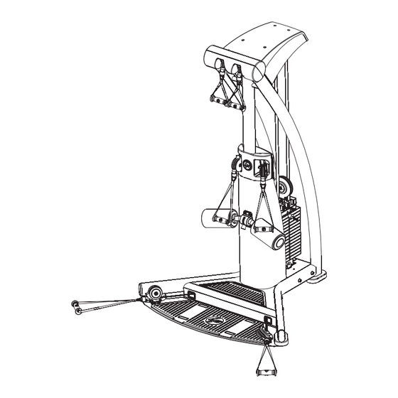
- Page 1 G5 CABLE MOTION ™ GYM SYSTEM ASSEMBLY INSTRUCTIONS G5-001 / CLASS H / 09/30/08 / 8289201 REV. B...
-
Page 2: Table Of Contents
SAFETY INFORMATION It is the sole responsibility of the purchaser of LIFE FITNESS products to read the owner's manual, warning labels and instruct all individuals, whether they are the end user or supervising personnel on proper usage of the equipment. - Page 3 6. Ensure that any person(s) making adjustments or performing maintenance or repair of any kind is quali- fied to do so. LIFE FITNESS will provide service and maintenance training at our corporate facility upon request or in the field if proper arrangements are made.
-
Page 4: G5 Warning Labels
G5 WARNING LABELS NOTE: Lock the weight stack when not using the gym. Make sure all the weight plates are rest- ing on the plate below with no gap in between. Insert the weight selector pin in the tab under- neath the weight stack. -
Page 5: Gym Dimensions
Resistance Ratio: Machine Weight: 500 pounds Weight Stack: 160 pounds GYM DIMENSIONS... -
Page 6: G5 Live Area
G5 LIVE AREA 12” 12” 11’-3” 13’-4” NOTE: The live area shows the extent of the G5 gym. It does not include the user. -
Page 7: Components List
NOTE: This component list is for ASSEMBLY ONLY. For ordering serviceable parts, please go to: http://us.home.lifefitness.com/content.cfm/servicedocuments ITEM NO. QTY. FRONT UPRIGHT UPPER SWIVEL PULLEYS LEFT UPRIGHT RIGHT UPRIGHT LEFT BASE RIGHT BASE FOOT PLATE GUIDE ROD WEIGHT PLATE HEAD PLATE PULLEY SELECTOR PIN TOP PLATE WEIGHT STACK CUSHION... -
Page 8: Hardware
HARDWARE ITEM NO. QTY. REQUIRED TOOLS ADJUSTABLE WRENCH EXTERNAL SNAP RING PLIERS PHILLIPS SCREW DRIVER ALLEN WRENCHES (4mm, 7mm, 8mm) WRENCHES (13mm, 17mm, 19mm) COMPONENTS LIST DESCRIPTION 3/8” WASHER M10 X 30MM SCREW M10 X 70MM SCREW M12 X 80MM SCREW 1/2”... - Page 9 3/8” WASHER (#39) M10 X 70MM SCREW (#41) M12 X 80MM SCREW (#42) M10 X 50MM HEX TENSION SCREW (#45) #10-32 X 3/4” PHILLIPS PAN HEAD SCREW (#50) M10 HEX NYLOCK NUT (#53) HARDWARE: M10 X 30MM SCREW (#40) M4 X 0.7mm ZINC PHILLIPS PAN HEAD SCREW (#47) M6 X 60MM SCREW (#51)
-
Page 10: Assembly Instructions
STEP 1: Slide the RIGHT BASE (6) over the MOUNTING TUBE (A) of the RIGHT UPRIGHT (4). Loosely secure the RIGHT BASE (6) and RIGHT UPRIGHT (4) to the FRONT UPRIGHT (1) using two M12 x 80mm SCREWS (42), four 1/2” WASHERS (43), and two M12 HEX NYLOCK NUTS (44) as shown. - Page 11 STEP 2: LOOSELY attach the FOOTPLATE (7) to the RIGHT BASE (6) and LEFT BASE (5) using four M10 x 70mm SCREWS (41) and four FLAT 3/8” WASHERS (39).
- Page 12 1” STEP 3: Position two WEIGHT STACK CUSHIONS (13) and GUIDE RODS (8) at the GUIDE ROD BRACKET (B) on the bot- tom of the FRONT UPRIGHT (1). NOTE: MAKE SURE THAT THE PLUGGED ENDS OF THE GUIDE RODS (8) ARE FACING UP. CAREFULLY slide one of the WEIGHT PLATES (9) over the top of the GUIDE RODS (8) and slowly lower the WEIGHT PLATE (9) on to the WEIGHT STACK CUSHIONS (13).
- Page 13 STEP 4: Remove one QUICK CONNECT from the end of one UPPER (LONG) CABLE (29). Insert the end (where the QUICK CONNECT was removed) of the UPPER (LONG) CABLE (29) through the UPPER SWIVEL PULLEYS (2) and follow routing illustration to the FLOATING PULLEYS (14) through to the HEAD PLATE PULLEY (10).
- Page 14 Slide Mechanism to insert or Exchange Handles STEP 5: Dissemble the QUICK CONNECT (32) by removing the two M5 HEX SCREWS (H) from the QUICK CONNECT COUPLER (D). Carefully remove the COMPRESSION SPRING (G), the QUICK CONNECT SLEEVE (F) and the QUICK CONNECT HOUSING (E).
- Page 15 STEP 6: Mount the RIGHT BOTTOM PLATE (16) and the LEFT BOTTOM PLATE (17) to the FRONT UPRIGHT (1) using two 10-32 x 3/4” PHILLIPS PAN HEAD SCREWS (50) for each plate. Place the FRONT SHROUD (15) around the FRONT UPRIGHT (1). Align the bottom mounting holes of the FRONT SHROUD (15) with the remaining mounting holes on the RIGHT BOTTOM PLATE (16) and the LEFT BOTTOM PLATE (17).
- Page 16 STEP 7: Remove one QUICK CONNECT from the end of one LOWER (SHORT) CABLE (30). Insert the end (where the QUICK CONNECT was removed) of the the LOWER (SHORT) CABLE (30) through the LOWER RIGHT PULLEY (J) and through the access hole in the FOOTPLATE (7). Continue routing the cable as shown ending at the RIGHT MID PULLEY ASSEMBLY (K).
- Page 17 STEP 8: Attach the BACK THIGH HOLD CLAMP (18) to the the FRONT UPRIGHT (1) by using two M6 x 60mm SCREWS (51) and two 1/4” WASHERS (52) from the back of the FRONT UPRIGHT (1). Attach the THIGH HOLD DOWN (19) to the FRONT UPRIGHT (1) by using four M10 x 70mm SCREWS (41), eight 3/8”...
- Page 18 STEP 9: Attach the TOP FRONT COVER (21) to the TOP BACK COVER (20) using eight M4 ZINC PHILLIPS PAN HEAD SCREWS (54). DO NOT OVERTIGHTEN SCREWS INTO PLASTIC PARTS.
- Page 19 STEP 10: Insert the ball end of one GUIDE CABLE (31) through the eye hook on one FLOATING PULLEYS (14). Insert and hook the ball end of the cable into the SLOTTED BUSHING (N) located at the bottom of the frame located directly below the FLOATING PULLEYS (14).
- Page 20 STEP 11: Assemble the MOUNTING SHEET (22) to the top of the FRONT UPRIGHT (1) using two M10 x 20mm SCREWS (48) and two 3/8” WASHERS (39). Tighten screws SECURELY. Attach the TOP LEFT COVER (25), the TOP RIGHT COVER (24) and the TOP COVER (23) to the MOUNTING SHEET (22) using four M4 x 0.7 ZINC PHILLIPS PAN HEAD SCREWS (47).
- Page 21 STEP 12: Referencing step 5, at the UPPER SWIVEL PULLEYS (2) push back on the QUICK CONNECT SLEEVE (F) at the end of each cable and attach the SHORT HANDLES (26). Repeat the process for attaching the ADJUSTABLE HANDLES (28) to the lower cable ends and the MEDIUM HAN- DLES (27) to the middle cable ends.
-
Page 22: General Maintenance
Please note: * We recommend cleaning your product (pads and frame) on a regular basis, using warm soapy water. Touch-up paint can be purchased from your Life Fitness cus- tomer service representative at (800) 351-3737. * Inspect equipment before each use. Tighten all loose connections and replace worn parts immediately. -
Page 23: Limited Warranty
LIMITED WARRANTY ON FRAME AND WELDS. If the frame of the Life Fitness product or a weld should crack or break, it will be repaired or replaced by Life Fitness. Terms: IN HOME USE ONLY: Lifetime – for so long as the Customer owns the Life Fitness product;... -
Page 24: Corporate Headquarters
Nippon Brunswick Bldg., #8F 5-27-7 Sendagaya Shibuya-Ku, Tokyo Japan 151-0051 Telephone: (+81) 3.3359.4309 Fax: (+81) 3.3359.4307 China and Hong Kong Life Fitness Asia Pacific LTD Room 2610, Miramar Tower 132 Nathan Road Tsimshatsui, Kowloon HONG KONG Telephone: (+852) 2891.6677 Fax: (+852) 2575.6001 All Other Asia Pacific countries &...
Need help?
Do you have a question about the Cable Motion 39721 and is the answer not in the manual?
Questions and answers