Table of Contents
Advertisement
Quick Links
Download this manual
See also:
Owner's Manual
Advertisement
Table of Contents

Related Manuals for Bayliner 265


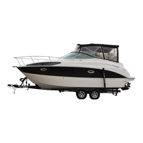
Summary of Contents for Bayliner 265
-
Page 3: Engine Serial Number
This document discloses subject matter in which Bayliner has proprietary rights. The information and design disclosed herein were originated by and are the prop- erty of Bayliner. Neither receipt nor possession thereof confers or transfers any right to reproduce, copy, alter or disclose the document or any part thereof, any information contained therein, or to construct boats or any item from it, except by written permission from or written agreement with Bayliner. -
Page 4: Table Of Contents
CONTENTS Chapter 1: Welcome Aboard! Chapter 4: Controls & Gauges Dimensions and Tank Capacities Steering Layout Views Shift/Throttle Control Dealer Service Power Trim and Tilt Warranty Information Trim Tabs Boating Experience Gauges 34 Cleaning Gauges Engine & Accessories Guidelines 34 Gauge Fogging 3 Propeller 34 Radio Transmission Interference Engine &... - Page 5 Chapter 7: Deck Equipment Chapter 12: Electrical System Cleats and Tow Eyes 12-Volt DC System 58 Battery Windlass (If Equipped) 58 Battery Switch (If Equipped With One Battery) Ski-Tow Tower (If Equipped) 59 Battery Switch (If Equipped With 46 Attaching the Ski-Tow Rope Two Batteries) 47 Folding the Ski-Tow Tower 59 Battery Switch Positions...
- Page 6 Hazard Boxes & Symbols The hazard boxes and symbols shown below are used throughout this supplement to call attention to potentially dan- gerous situations which could lead to either personal injury or product damage. Read ALL warnings carefully and follow all safety instructions. DANGER! This box alerts you to immediate hazards which WILL cause severe personal injury or death if the warning is ignored.
-
Page 7: Chapter 1: Welcome Aboard
265 • Owner’s Manual Supplement Chapter 1: Welcome Aboard! • This Owner’s Manual Supplement provides information about your boat that is not covered in the Cruiser & Yacht Owner’s Manual. • Before using your boat, study this Owner’s Manual Supplement, the Cruiser & Yacht Owner’s Manual, and all engine and accessory literature carefully. -
Page 8: Dealer Service
• Bayliner offers a Limited Warranty on each new Bayliner purchased through an authorized Bayliner dealer. • A copy of the Limited Warranty was included in your owner’s packet. • If you did not receive a copy of the Limited Warranty, please contact your Bayliner dealer or call 360-435-8957 for a copy. -
Page 9: Propeller
Refer to the engine manual for engine RPM ratings. The engine should reach, but not exceed its full rated RPM when full-throttle is applied. Immediately contact your local Bayliner dealer if: • The engine cannot reach its full rated RPM when full-throttle is applied, or;... -
Page 10: Safety Standards
Chapter 1: Welcome Aboard! 265 • Owner’s Manual Supplement Safety Standards DANGER! FALLING and ROTATING PROPELLER HAZARD! • NEVER allow anyone to ride on parts of the boat not designed for such use. • Sitting on seat backs, lounging on the forward deck, bow riding, gunwale riding or occupying the transom platform while underway is especially hazardous and will cause personal injury or death. -
Page 11: Special Care For Moored Boats
265 • Owner’s Manual Supplement Chapter 1: Welcome Aboard! Special Care For Moored Boats NOTICE • To help seal the hull bottom and reduce the possibility of gelcoat blistering on moored boats, apply an epoxy barrier coating. • The barrier coating should be covered with several coats of anti-fouling paint. -
Page 12: Boat Lifting
Chapter 1: Welcome Aboard! 265 • Owner’s Manual Supplement Boat Lifting WARNING! PERSONAL INJURY and /or PRODUCT OR PROPERTY DAMAGE HAZARD! • Lifting slings may slip on the hull. • Avoid serious injury or death by securing the lifting slings together before lifting. -
Page 13: Carbon Monoxide (Co)
265 • Owner’s Manual Supplement Chapter 1: Welcome Aboard! Carbon Monoxide (CO) DANGER! • Carbon monoxide gas (CO) is colorless, odorless, tasteless, and extremely dangerous. • All engines and fuel burning appliances produce CO as exhaust. • Prolonged exposure to low concentrations or very quick exposure to high concentrations will cause BRAIN DAMAGE or DEATH. -
Page 14: Where And How Co Can Accumulate
Chapter 1: Welcome Aboard! 265 • Owner’s Manual Supplement Where and How CO Can Accumulate Stationary Conditions That Increase CO Accumulations Include: A. Using engine, generator, or other fuel B. Mooring too close to another boat that is burning device when boat is moored in a using its engine, generator, or other fuel confined space. -
Page 15: Co Checklists
265 • Owner’s Manual Supplement Chapter 1: Welcome Aboard! CO Checklists Trip Checklist Make sure you know where the exhaust outlets are located on your boat. Educate all passengers about the symptoms of CO poisoning and where CO may accumulate. -
Page 16: More Information
Chapter 1: Welcome Aboard! 265 • Owner’s Manual Supplement More Information For more information about how you can prevent carbon monoxide poisoning on recreational boats and other ways to boat more safely, contact: United States Coast Guard National Marine Manufacturers American Boat &... -
Page 17: Chapter 2: Locations
265 • Owner’s Manual Supplement Chapter 2: Locations Exterior Views Hull Views VENTED WATER PORTLIGHTS VENTED FUEL FILL FITTING FILL FITTING AFT BILGE PUMP DRAIN WASTE TANK VENT STARBOARD HULLSIDE ANCHOR LOCKER DRAIN COCKPIT ENTERTAINMENT SHOWER SUMP FORWARD BILGE HEAD SINK... -
Page 18: Deck Views
Chapter 2: Locations 265 • Owner’s Manual Supplement Deck Views... -
Page 19: Helm
265 • Owner’s Manual Supplement Chapter 2: Locations Helm... -
Page 20: Component Locations
Chapter 2: Locations 265 • Owner’s Manual Supplement Component Locations 12-Volt Accessory Outlets: • One located at the helm, on the switch panel. 12-VOLT OUTLET • One located on the aft end of the lower galley cabinet. AUDIO JACKS (IF EQUIPPED) •... - Page 21 265 • Owner’s Manual Supplement Chapter 2: Locations Air Conditioner Unit AIR CONDITIONER (If Equipped): (IF EQUIPPED) • Located in the storage locker under the star- board aft seat cushion in the v-berth. Air Conditioner Control Panel (If Equipped): • Located on the forward...
- Page 22 Chapter 2: Locations 265 • Owner’s Manual Supplement Battery Switch(es): • Located inside the transom storage locker. BATTERY SWITCH(ES) Bilge Pump and Float Switch - Aft: • Located in the engine room, forward of the engine. AFT BILGE PUMP & FLOAT SWITCH Bilge Pump and Float Switch - Forward: •...
- Page 23 265 • Owner’s Manual Supplement Chapter 2: Locations Carbon Monoxide Monitor: • Located on the valance on the star- board aft corner of the v-berth ceiling CO MONITOR Circuit Breakers: SHORE POWER MASTER The following circuit breakers CIRCUIT BREAKER(S) are all located inside the tran- som storage locker: •...
- Page 24 Chapter 2: Locations 265 • Owner’s Manual Supplement Depth Sounder Thru-hull Transducer: • Located in the engine room, forward of the engine. TRANSDUCER Engine Circuit Breaker: • Located on the engine. Fire Suppression System Manual Discharge T-Handle (If Equipped): • Located to the right of the helm...
- Page 25 265 • Owner’s Manual Supplement Chapter 2: Locations Freshwater Fill Vented Thru-hull Fitting: FRESHWATER FILL • Located amidship on the starboard hullside, VENTED THRU-HULL FITTING just below the gunnel. Freshwater Pump: • Located under the bottom entry step. • Access by lifting up the bottom entry step.
- Page 26 Chapter 2: Locations 265 • Owner’s Manual Supplement Freshwater Tank: • Located amidship in the bilge. • Access by lifting up the bottom entry step. BOTTOM ENTRY STEP Fuel Fill Vented Thru-hull Fitting: FUEL FILL VENTED • Located on the starboard hullside, aft of THRU-HULL FITTING the freshwater fill vented fitting.
- Page 27 265 • Owner’s Manual Supplement Chapter 2: Locations Fuse Blocks: WALL HATCH DOOR • Located inside the starboard wall hatch in the aft-berth. Macerator Switches (If Equipped): • Located to the right of the helm. MACERATOR SWITCHES (IF EQUIPPED) Macerator Underwater Discharge Seacock...
- Page 28 Chapter 2: Locations 265 • Owner’s Manual Supplement Marine Head Seawater Intake Seacock: • Located under the bottom entry step. • Access by lifting up the bottom entry step. BOTTOM ENTRY STEP Power Trim and Tilt Pump & Reservoir POWER TRIM & TILT PUMP & RESERVOIR •...
- Page 29 265 • Owner’s Manual Supplement Chapter 2: Locations Shore Power Master Circuit Breakers (If Equipped): • Located inside the transom storage locker. SHORE POWER MASTER CIRCUIT BREAKER(S) Shower Sump Pump Box: • Located under the bottom entry step. • Access by lifting up the bottom entry step.
- Page 30 Chapter 2: Locations 265 • Owner’s Manual Supplement Spotlight Control Panel (If Equipped): • Located at the helm. SPOTLIGHT CONTROL PANEL (IF EQUIPPED) Trim Tab Pump & Reservoir • Located on the port aft wall TRIM TAB PUMP & RESERVOIR of the engine room.
- Page 31 265 • Owner’s Manual Supplement Chapter 2: Locations Waste Pump-Out Deck Fitting (If Equipped): • Located on the starboard corner of the aft WASTE FITTING deck, just above the swim platform and next (IF EQUIPPED) to the transom door. Water Heater •...
-
Page 32: Chapter 3: Propulsion & Related Systems
265 • Owner’s Manual Supplement Chapter 3: Propulsion & Related Systems Engine Read the engine operation and maintenance manuals before starting or doing any maintenance on the engine. Bilge Blower System WARNING! FIRE/EXPLOSION HAZARD • Use of the bilge blower system is NOT A GUARANTEE that explosive fumes have been removed. -
Page 33: Fuel System
265 • Owner’s Manual Supplement Chapter 3: Propulsion & Related Systems Fuel System WARNING! FIRE, EXPLOSION AND OPEN FLAME HAZARD! • It is very important that the fuel system be inspected thoroughly the first time it is filled and at each subsequent filling. -
Page 34: Fuel Fill & Vent
Chapter 3: Propulsion & Related Systems 265 • Owner’s Manual Supplement DIESEL ENGINE FUEL LINE ROUTING (IF EQUIPPED) FUEL SHUT- OFF VALVE FUEL FILTER/WATER SEPARATOR FUEL TANK FUEL RETURN LINE VENTED FUEL FILL FUEL LINE TO ENGINE Fuel Fill & Vent •... -
Page 35: Gas Engine Fuel Filters
265 • Owner’s Manual Supplement Chapter 3: Propulsion & Related Systems Gas Engine Fuel Filters • The fuel pickup tube, located inside the fuel tank, is equipped with a fine mesh screen filter. • MPI engine fuel systems include an inline fuel filter. -
Page 36: Quick Oil Drain System (Gas Engine Only)
Chapter 3: Propulsion & Related Systems 265 • Owner’s Manual Supplement Quick Oil Drain System (Gas Engine Only) The quick oil drain hose was attached to the engine oil pan at the factory. However, some minor assembly is still needed before you can use this system. -
Page 37: Fire Suppression System (If Equipped)
265 • Owner’s Manual Supplement Chapter 3: Propulsion & Related Systems Fire Suppression System (If Equipped) • The fire suppression system is designed to extinguish engine compartment fires. • Before using your boat for the first time, read the fire suppression system’s... -
Page 38: Chapter 4: Controls & Gauges
265 • Owner’s Manual Supplement Chapter 4: Controls & Gauges Steering • This boat features a power assisted rack-and-pinion steering system. • For information about the ‘power assist fluid reservoir’, refer to the engine operation and maintenance manual. • Boat steering is not self-centering. -
Page 39: Trim Tabs
265 • Owner’s Manual Supplement Chapter 4: Controls & Gauges Trim Tabs WARNING! LOSS OF CONTROL HAZARD! Improper use of trim tabs will cause loss of control! • Do NOT allow anyone unfamiliar with trim tabs to use them. • Do NOT use trim tabs in a following sea as they will cause broaching or other unsafe handling characteristics. -
Page 40: Gauges
Chapter 4: Controls & Gauges 265 • Owner’s Manual Supplement Gauges Cleaning Gauges CAUTION PRODUCT or PROPERTY DAMAGE HAZARD! • Use only mild soap and water to clean the gauge lenses and bezels. • Use of other cleaners, including common window cleaning solutions, may cause the lenses to crack. -
Page 41: Chapter 5: Navigation & Communication Equipment
265 • Owner’s Manual Supplement Chapter 5: Navigation & Communication Equipment Read the manuals for all navigation & communication equipment before using these systems. Compass NOTICE • Compass accuracy can be affected by many factors. • Have a qualified technician calibrate your compass. -
Page 42: Chapter 6: Plumbing
265 • Owner’s Manual Supplement Chapter 6: Plumbing Bilge Pumps NOTICE Discharge of oil, oil waste or fuel into navigable waters is prohibited by law. Violators are sub- ject to legal action by the local authorities. FORWARD BILGE PUMP THRU-HULLS AFT BILGE PUMP &... -
Page 43: Bilge Pump Testing
265 • Owner’s Manual Supplement Chapter 6: Plumbing Bilge Pump Testing • The bilge pumps are vital to the safety of your boat. • Test the bilge pumps often to make sure they are working properly. Testing process: 1. One at a time, turn On each bilge pump switch at the helm. -
Page 44: Autofloat Switches
Chapter 6: Plumbing 265 • Owner’s Manual Supplement Autofloat Switches • The automatic bilge pumps use float (autofloat) switches to automatically turn On the pumps whenever water rises to a preset level in the bilge. • The autofloat switches are normally mounted next to the bilge pumps they control. -
Page 45: Seawater Systems
265 • Owner’s Manual Supplement Chapter 6: Plumbing Seawater Systems Seacocks CAUTION SYSTEM DAMAGE HAZARD! • Before using a seawater intake system, make sure that the system’s seacock is in the Open position before the system is started and keep the seacock Open until the system is shut Off. -
Page 46: Freshwater System
Chapter 6: Plumbing 265 • Owner’s Manual Supplement Freshwater System WARNING! • Only use safe drinking (potable) water in your boat’s freshwater system. • Only use an FDA approved, white 'drinking water safe' hose to fill the freshwater tank. • NEVER use a common garden hose for drinking water. -
Page 47: Freshwater System Winterization
265 • Owner’s Manual Supplement Chapter 6: Plumbing Freshwater System Winterization CAUTION WATER SYSTEM DAMAGE HAZARD! NEVER blow compressed air through the water system when all of the faucets are Closed. 1. Turn On the freshwater pump switch. 2. Open all of the faucets and showers and let the freshwater system drain completely. -
Page 48: Water Heater (If Equipped)
Chapter 6: Plumbing 265 • Owner’s Manual Supplement Water Heater (If Equipped) WAR NING! SCALDING HAZARD! Water heated by the water heater can be hot enough to scald the skin. CAUTION! WATER HEATER DAMAGE HAZARD! • Do NOT turn On the water heater electrical circuit on the AC panel until the water heater tank is COMPLETELY filled with water. -
Page 49: Transom Shower (If Equipped)
265 • Owner’s Manual Supplement Chapter 6: Plumbing Transom Shower (If Equipped) • Read the manufacturer’s instructions before using the transom shower for the first time. • The freshwater pump switch must be turned TRANSOM SHOWER (IF EQUIPPED) On before using the transom shower. -
Page 50: Marine Head With Holding Tank (If Equipped)
Chapter 6: Plumbing 265 • Owner’s Manual Supplement Marine Head with Holding Tank (If Equipped) NOTICE Check with local authorities for regulations regarding the legal use of marine head systems. • Before using this system, read the marine head operation and maintenance manual. -
Page 51: Chapter 7: Deck Equipment
265 • Owner’s Manual Supplement Chapter 7: Deck Equipment Cleats and Tow Eyes WARNING! PERSONAL INJURY and /or PRODUCT or PROPERTY DAMAGE HAZARD! NEVER lift the boat using the cleats, bow and stern eyes. Carefully read the section on towing in the Cruiser & Yacht Owner’s Manual before: •... -
Page 52: Ski-Tow Tower (If Equipped)
Chapter 7: Deck Equipment 265 • Owner’s Manual Supplement Ski-Tow Tower (If Equipped) WARNING! PERSONAL INJURY and /or PRODUCT or PROPERTY DAMAGE HAZARD! Failure to follow these guidelines can result in injury or death: • Read all warning labels on ski-tow tower. -
Page 53: Folding The Ski-Tow Tower
265 • Owner’s Manual Supplement Chapter 7: Deck Equipment Folding the Ski-Tow Tower WARNING! PERSONAL INJURY and /or PRODUCT or PROPERTY DAMAGE HAZARD! • Folding or unfolding the ski-tow tower is a two person task. • Before each use of the folding ski-tow tower, make sure both lock-down bolts are tightened firmly. -
Page 54: Canvas
Chapter 7: Deck Equipment 265 • Owner’s Manual Supplement Canvas CAUTION PRODUCT or PROPERTY DAMAGE HAZARD! Take down and securely stow ALL canvas before transporting your boat by road. WINDSHIELD HINGE SECURING PIN SECURING PIN END EYE DECK HINGE 1. Slide the windshield hinges of the main bow (A) over the aft pre-drilled holes in the windshield frames (B) and insert the securing pins. -
Page 55: Canvas Care
265 • Owner’s Manual Supplement Chapter 7: Deck Equipment Canvas Care (see also, ‘Clear Vinyl Care’ on next page) • After each use, especially in saltwater, rinse the canvas with cold freshwater. • Before stowing, let the canvas air dry completely. -
Page 56: Clear Vinyl Care
Chapter 7: Deck Equipment 265 • Owner’s Manual Supplement Clear Vinyl Care CAUTION • NEVER store the clear vinyl pieces wet, as this will cause a milky film to develop. • NEVER fold or crease the clear vinyl pieces as cracking will occur. -
Page 57: Chapter 8: Appliances & Entertainment Systems
265 • Owner’s Manual Supplement Chapter 8: Appliances & Entertainment Systems NOTICE Always keep an approved ABC-type fire extinguisher in galley area. • The separate instruction sheets or manuals for all appliances and entertainment systems contain detailed instructions and important safeguards. -
Page 58: Alcohol Stove (If Equipped)
Chapter 8: Appliances & Entertainment Systems 265 • Owner’s Manual Supplement Alcohol Stove (If Equipped) DANGER! CARBON MONOXIDE POISONING HAZARD! • The alcohol stove is a source of dangerous carbon monoxide gas (CO). • Before using the alcohol stove, Open doors and windows to make sure there is enough fresh air for ventilation. -
Page 59: Alcohol/Electric Stove (If Equipped)
265 • Owner’s Manual Supplement Chapter 8: Appliances & Entertainment Systems Alcohol/Electric Stove (If Equipped) DANGER! CARBON MONOXIDE POISONING HAZARD! • The alcohol stove is a source of dangerous carbon monoxide gas (CO). • Before using the alcohol stove, Open doors and windows to make sure there is enough fresh air for ventilation. -
Page 60: Chapter 9: Convertible Seats, Beds, & Tables
265 • Owner’s Manual Supplement Chapter 9: Convertible Seats, Beds, & Tables Dinette to V-berth Sleeping Area 1. Pull up on the dinette table top (A) to remove it from the table post (B). 2. Unscrew the table post (B) counterclockwise and remove it from the post base (C). -
Page 61: Chapter 10: Lights
265 • Owner’s Manual Supplement Chapter 10: Lights Care and Maintenance All of the lights installed on your boat are of top quality, but you should be aware that failure may periodically occur for a variety of reasons: 1. There may be a blown fuse - replace the fuse. -
Page 62: Chapter 11: Heating & Air Conditioning System
265 • Owner’s Manual Supplement Chapter 11: Heating & Air Conditioning System Air Conditioning System (If Equipped) DANGER! CARBON MONOXIDE POISONING HAZARD! Dangerous carbon monoxide gas (CO) can be brought into the boat through the air conditioning system. CAUTION SYSTEM DAMAGE HAZARD! The air conditioning system’s seawater intake seacock must be Opened before turning On... -
Page 63: Chapter 12: Electrical System
265 • Owner’s Manual Supplement Chapter 12: Electrical System DANGER! EXTREME FIRE, SHOCK & EXPLOSION HAZARD! • To minimize the risks of fire and explosion, NEVER install knife switches or other arcing devices in the fuel compartments. • NEVER substitute automotive parts for marine parts. Electrical, ignition and fuel system parts were designed and manufactured to comply with rules and regulations that minimize risks of fire and explosion. -
Page 64: 12-Volt Dc System
Chapter 12: Electrical System 265 • Owner’s Manual Supplement 12-Volt DC System Battery The battery supplies electricity for lights, 12-volt accessories, and engine starting. The Electrical section of Chapter 8, in the Cruiser & Yacht Owner’s Manual, provides battery, care and maintenance instructions. -
Page 65: Battery Switch Positions
265 • Owner’s Manual Supplement Chapter 12: Electrical System Battery Switch (If Equipped With Two Batteries) CAUTION SHOCK & ELECTRICAL SYSTEM DAMAGE HAZARD! When the engine is running, NEVER turn Off the battery switch or disconnect the battery cables. Doing either could cause damage to your boat’s engine and/or electrical system components. -
Page 66: Fuses And Circuit Breakers
Chapter 12: Electrical System 265 • Owner’s Manual Supplement Fuses and Circuit Breakers • Fuses for the accessory items are on the fuse blocks. • Some equipment may have secondary fuse protection at the unit, or at the battery. • The DC circuit breakers for the stand-by loads, and the DC main circuit breaker for the engine and main accessory power, are located on the battery switch panel. -
Page 67: 110-Volt Ac System (If Equipped)
265 • Owner’s Manual Supplement Chapter 12: Electrical System 110-Volt AC System (If Equipped) CAUTION WATER HEATER DAMAGE HAZARD! • Do NOT turn On the water heater breaker on the 110-Volt AC panel until the water heater tank is completely filled with water. -
Page 68: Shore Power (If Equipped)
Chapter 12: Electrical System 265 • Owner’s Manual Supplement Shore Power DANGER! FIRE, EXPLOSION & SHOCK HAZARD! • Do NOT alter the shore power connectors and use only compatible connectors. • Before plugging in or unplugging the shore power cord to your boat, make sure all breakers and switches on the AC master panel are turned Off. -
Page 69: Connecting To Shore Power
265 • Owner’s Manual Supplement Chapter 12: Electrical System • The single shore power 110-volt/60-hertz, AC system (if equipped) features one, 110-volt/30-amp, shore power receptacle. • If your boat is equipped with an air conditioning system, a second (dual) 110-volt/30-amp inlet has been installed. -
Page 70: Electrical Routings
Chapter 12: Electrical System 265 • Owner’s Manual Supplement Electrical Routings 12-Volt DC Deck Electrical Harnesses NOTE: VIEW IS OF UNDER SIDE OF DECK. STARBOARD NAVIGATION LIGHT PORT NAVIGATION LIGHT SPOTLIGHT (IF EQUIPPED) WINDLASS (IF EQUIPPED) HORN SPEAKER SPEAKER CABIN LIGHT... -
Page 71: 12-Volt Dc Hull Electrical Harnesses
265 • Owner’s Manual Supplement Chapter 12: Electrical System 12-Volt DC Hull Electrical Harnesses GALLEY PLUGS SHOWER SUMP PUMP (IF EQUIPPED) FORWARD BILGE PUMP HEAD INTAKE BONDING ELECTRIC HEAD (IF EQUIPPED) FRESHWATER PUMP MACERATOR SWITCH (IF EQUIPPED) FIRE EXTINGUISHER SYSTEM CONTROL... -
Page 72: 110-Volt Ac Hull Electrical Harnesses (If Equipped)
Chapter 12: Electrical System 265 • Owner’s Manual Supplement 110-Volt AC Hull Electrical Harnesses (If Equipped) AIR CONDITIONER (IF EQUIPPED) GFI OUTLET MICROWAVE STOVE LOCKER OUTLET LOCKER OUTLET REFRIGERATOR HEAD OUTLET AC PANEL GFI OUTLET AIR CONDITIONER PUMP JUNCTION BOX... -
Page 73: Wiring Diagrams
265 • Owner’s Manual Supplement Chapter 12: Electrical System Wiring Diagrams 12-Volt DC Electrical System... -
Page 74: Single Shore Power (If Equipped)
Chapter 12: Electrical System 265 • Owner’s Manual Supplement Single Shore Power (If Equipped) -
Page 75: Dual Shore Power (If Equipped)
265 • Owner’s Manual Supplement Chapter 12: Electrical System Dual Shore Power (If Equipped) -
Page 76: Windlass Wiring Diagram (If Equipped)
Chapter 12: Electrical System 265 • Owner’s Manual Supplement Windlass Wiring Diagram (If Equipped) Fire Suppresion System Wiring Diagram (If Equipped) -
Page 77: Important Records
265 • Owner’s Manual Supplement Important Records Selling Dealer Key Numbers Name Of Dealership Ignition Other Address Electronics Phone/FAX/E-mail Manufacturer Model Name/Number Sales Manager Service Manager Serial Number Engine Manufacturer Model Name/Number Manufacturer Model Name/Number Serial Number Engine Serial Number... -
Page 78: Float Plan
265 • Owner’s Manual Supplement Float Plan Before going boating, fill out a copy of this float plan (or similar) and leave it with a reliable person whom you can depend on to contact the Coast Guard or other rescue organization, if you do not return as scheduled. - Page 79 265 • Owner’s Manual Supplementl Float Plan Survival Equipment Trip Expectations Marine Radio (Yes/No) Type Frequencies Departing From Number of PFDs Flares (Yes/No) Mirror (yes or no) Departure Date Departure Time Smoke Signals (Yes/No) Flashlight (Yes/No) Food (Yes/No) Stopover 1...
- Page 80 Owner’s Notes...
- Page 81 Owner’s Notes...
- Page 82 Owner’s Notes...
- Page 84 Part Number 1781267 Bayliner • P.O. Box 9029 • Everett, WA 98206 • 360-435-5571...
Need help?
Do you have a question about the 265 and is the answer not in the manual?
Questions and answers
My trim gauge and tach gauge aren't working. The tach gauge will work briefly if I tap hard on the console top
The trim gauge and tachometer on a Bayliner 265 may not be working due to several possible causes:
1. Electrical Connection Issues – Loose, corroded, or disconnected wiring may prevent signals from reaching the gauges.
2. Faulty Sending Units – A malfunctioning trim sender or tachometer signal source (such as the alternator or ignition system) could cause failure.
3. Radio Interference – VHF or other radio transmissions may cause erratic tachometer readings, though this does not cause permanent failure.
4. Blown Fuse or Power Supply Issue – A blown fuse or disrupted power supply may prevent the gauges from functioning.
5. Gauge Failure – The gauges themselves may be defective or damaged.
Checking the wiring, fuses, and sending units should help diagnose the problem.
This answer is automatically generated
How to remove sliding cabin door? Interior vinyl is preventing door to slide open or close