Sign In
Upload
Download
Table of Contents
Contents
Add to my manuals
Delete from my manuals
Share
URL of this page:
HTML Link:
Bookmark this page
Add
Manual will be automatically added to "My Manuals"
Print this page
×
Bookmark added
×
Added to my manuals
Manuals
Brands
Bayliner Manuals
Boat
Trophy 1703FS
Owner's manual supplement
Bayliner Trophy 1703FS Owner's Manual Supplement
Fishing boats
Hide thumbs
Also See for Trophy 1703FS
:
Owner's manual
(40 pages)
1
2
3
Table Of Contents
4
5
6
7
8
9
10
11
12
13
14
15
16
17
18
19
20
21
22
23
24
25
26
27
28
29
30
31
32
33
34
35
36
37
38
39
40
41
42
43
44
45
46
47
48
49
50
51
52
53
54
55
56
57
58
59
60
page
of
60
Go
/
60
Contents
Table of Contents
Bookmarks
Table of Contents
Hull Identification Number
Table of Contents
Chapter 1: About this Manual
Dealer Service
Boating Experience
Engine & Accessories Guidelines
Qualified Maintenance
Special Care for Moored Boats
Safety Standards
Hazard Warning Symbols
Carbon Monoxide (CO)
Sources of CO
Carbon Monoxide Alarm System
What to Do if Carbon Monoxide Is Detected
Chapter 2: Product Specifications
Specifications
Chapter 3: Components/Systems
Electrical System
12-Volt DC System- Fuses, Circuit Breakers and Switches
Shore Power/110 Volt AC System
Controls
Trim Tabs
Navigation and Interior Lights
Compass
Depth Finder
Anchoring
Fuel System
Fuel Fills and Vents
Fuel Filters
Bilge Blower (2052 FD)
Quick Oil Drain System (2052 FD)
Fire Port System (2052 FD)
Bilge Pump
Autofloat Switch
Fresh Water System
Marine Head with Pump-Out
Portable Toilet
Bait Well System
Alcohol Stove
Canvas Top Installations
Center Console Models
Bowrider Models
Cuddy Cabin Models
Chapter 4: Drawings & Diagrams
1700 (Ft)
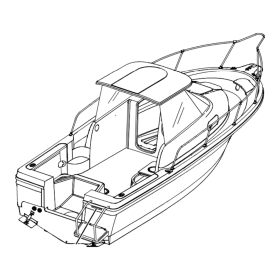
1703 (Fs)
1802 (Fj)
Hull Exterior Hardware
1900 (Fg)
1903 (Fe)
2002 (Ff)
2052 (Fd)
2503 (Fm)
2509 (Fw)
Deck Hardware
2802 (Fh)
Chapter 4: Wiring Diagrams
Shore Power
Single Engine (Outboard), Typical
Twin Engine (Outboard), Typical
Stern Drive, Typical
Limited Warranty
What Is Not Covered
Other Limitations
Your Obligation
Advertisement
Quick Links
1
Specifications
2
2002 (Ff)
3
2052 (Fd)
Download this manual
See also:
Owner's Manual
Table of
Contents
Previous
Page
Next
Page
1
2
3
4
5
Advertisement
Table of Contents
Need help?
Do you have a question about the Trophy 1703FS and is the answer not in the manual?
Ask a question
Questions and answers
Related Manuals for Bayliner Trophy 1703FS
Boat Bayliner Trophy 1703FS Owner's Manual
Fishing boats (40 pages)
Boat Bayliner 175 Owner's Manual
175 bayliner (44 pages)
Boat Bayliner 175 Owner's Manual
175 bayliner (40 pages)
Boat Bayliner 175 Bowrider Owner's Manual
(60 pages)
Boat Bayliner Capri 1400 Bowrider Owner's Manual
(22 pages)
Boat Bayliner Capri 16' Owner's Manual Supplement
(48 pages)
Boat Bayliner 170 Bowrider Owner's Manual Supplement
(61 pages)
Boat Bayliner 190 Bowrider Owner's Manual Supplement
(61 pages)
Boat Bayliner 185 Owner's Manual
Runabouts (88 pages)
Boat Bayliner 185 Owner's Manual
Runabouts (76 pages)
Boat Bayliner 195 Owner's Manual Supplement
Bowrider (60 pages)
Boat Bayliner 160 Owner's Manual
Boat (52 pages)
Boat Bayliner 197 Owner's Manual
Deck boats (88 pages)
Boat Bayliner 1995 3288 Owner's Manual
(45 pages)
Boat Bayliner 1995 Ciera Owner's Manual
(58 pages)
Boat Bayliner 1950 1952 1954 2150 2152 Owner's Manual Supplement
(56 pages)
This manual is also suitable for:
Trophy 1700ft
Trophy 1900fg
Trophy 1802fj
Trophy 2002ff
Trophy 2052fd
Trophy 2503fm
...
Show all
Trophy 2509fw
Trophy 2802fh
Table of Contents
Save PDF
Print
Rename the bookmark
Delete bookmark?
Delete from my manuals?
Login
Sign In
OR
Sign in with Facebook
Sign in with Google
Upload manual
Upload from disk
Upload from URL


Need help?
Do you have a question about the Trophy 1703FS and is the answer not in the manual?
Questions and answers