
Related Manuals for DTS FOS 100 POWER SOLO FULL RGBW


Summary of Contents for DTS FOS 100 POWER SOLO FULL RGBW
- Page 1 FOS 100 POWER SOLO FOS 100 POWER User’s Manual rel 1.2 GB D.T.S. Illuminazione s.r.l. – ITALY http://www.dts-lighting.it Made in Italy...
- Page 2 Le informazioni contenute in questo documento sono state attentamente redatte e controllate. Tuttavia non è assunta alcuna responsabilità per eventuali inesattezze. Tutti i diritti sono riservati e questo documento non può essere copiato, fotocopiato, riprodotto per intero o in parte senza previo consenso scritto della D.T.S . D.T.S.
-
Page 3: Table Of Contents
INDEX: 1- SYMBOLS 2- GENERAL WARNING 3- GENERAL WARRANTY CONDITION 4- TECHNICAL FEATURES 5- MAIN ELECTRICAL CHARACTERISTICS 6- ACCESSORIES 7- IMPORTANT SAFETY INFORMATION 7.1 Fire prevention 7.2 Prevention of electric shock 7.3 Safety 8- INPUT / OUTPUT CONNECTIONS 9- DMX SIGNAL CONNECTION 9.1 DMX Addresses 9.2 Selecting the DMX address 10- FIRMWARE UPDATING... -
Page 4: Symbols
1- SYMBOLS Graphic symbols used on this manual THIS SYMBOL INDICATES A HOT SURFACE THIS SYMBOL INDICATES ELECTRIC SHOCK RISK THIS SYMBOL INDICATES GENERAL RISK THIS SYMBOL MEANS “DO NOT PLACE THE UNIT ON INFLAMMABLE SURFACES” THIS SYMBOL INDICATES THE MINIMUM 10cm DISTANCE TO BE KEPT BETWEEN THE DEVICE AND THE LIT OBJECT... -
Page 5: Technical Features
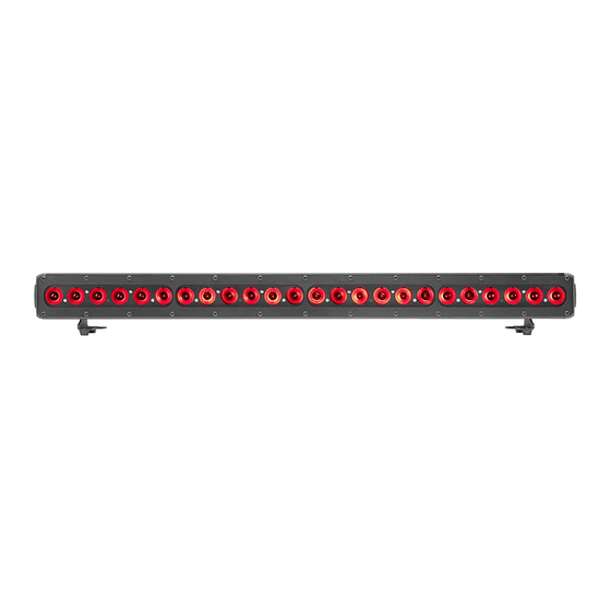
4- TECHNICAL FEATURES OVERVIEW FOS 100 POWER is the most powerful model in the FOS line of compact LED bars, designed for lighting and colouring large surfaces with a homogeneous projection. FOS 100 POWER is ideal in a variety of applications, either indoor or outdoor, such as: lighting building facades, monuments, public and commercial spaces;... -
Page 6: Main Electrical Characteristics
Product codes: 03.LB030S.26.FW10 FOS 100 POWER SOLO IP20 FULLWHITE NARROW GREY SILVER 03.LB030S.26.FW25 FOS 100 POWER SOLO IP20 FULLWHITE MEDIUM GREY SILVER 03.LB030S.26.FW40 FOS 100 POWER SOLO IP20 FULLWHITE WIDE GREY SILVER 03.LB030S.FW10 FOS 100 POWER SOLO IP20 FULLWHITE NARROW BLACK 03.LB030S.FW25 FOS 100 POWER SOLO IP20 FULLWHITE MEDIUM BLACK 03.LB030S.FW40... -
Page 7: Accessories
6- ACCESSORIES As standard (IP20) 1 x User’s Manual 1 x POWERCON IN male cable connector (FOS 100 POWER SOLO) (D.T.S. Code: 0520P014) 1 x POWERCON OUT male cable connector (FOS 100 POWER SOLO) (D.T.S. Code: 0520P029) 1 x XLR 5 poles male cable connector (D.T.S. Code: 0508B028) 1 x XLR 5 poles female cable connector (D.T.S. - Page 8 DIMENSIONS FOS 100 POWER SOLO Unit Dimensions Packing Dimensions (LxWxH) (LxWxH) 990 x 100 x 84,5 mm 1060 x 160 x 200 mm Weight Weight 7 Kg 8,5 Kg 100 mm 140 mm 990 mm...
- Page 9 FOS 100 POWER Unit Dimensions Packing Dimensions (LxWxH) (LxWxH) 990 x 56 x 84,5 mm 1060 x 160 x 200 mm Weight Weight 5,5 Kg 7 Kg 56 mm 140 mm 990 mm...
-
Page 10: Important Safety Information
7- IMPORTANT SAFETY INFORMATION 7.1 Fire prevention: Never locate the fixture on any flammable surface. Minimum distance from flammable materials: 10 cm. 10cm Minimum distance from the closest illuminable surface: 10 cm. 7.2 Prevention from electric shock: High voltage is present inside the unit. Unplug the unit prior to performing any operation which involves touching the inside of the unit. - Page 11 8- INPUT / OUTPUT CONNECTIONS FOS 100 POWER SOLO (IP20) M16 LED output DMX IN/OUT XLR 5 pins Male / Female Female panel connector Panel Connectors Mains 90-260 V AC Mains 90-260 V AC 50-60 Hz output Powercon 50-60 Hz input Powercon Female panel connector Female panel connector MAX load:...
- Page 12 FOS 100 POWER (IP65) M16 LED input Male cable connector...
-
Page 13: Dmx Signal Connection
9- DMX SIGNAL CONNECTION (FOS 100 POWER SOLO): The unit operates using a digital DMX 512 signal. Connection between the controller and the unit or between units must be carried out using a two pair screened ø 0.5 mm. Ensure that the conductors do not touch each other. Do not connect the cable ground to the DMX connector chassis. -
Page 14: 9.1 Dmx Addresses
(default), 6 DMX channels mode (Shutter + Dimmer + RGBW), WALL mode (6 DMX channels; for use with DTS Wall mounted DMX controller 0514L007), M4CH mode (5 DMX channels; Dimmer + RGBW), RGBW mode (4 channels), 1 DMX channel mode or CUSTOM DMX mode (not yet implemented). - Page 15 USB-DMX Driver for the D.T.S. RED BOX interface. D.T.S. Firmware upgrade utility program. (The driver and the installation procedure are available in our web site www.dts-lighting.it) Updating the software version. Please follow the procedure below to perform the update: 1. Install the D.T.S. RED BOX USB-DMX driver on the PC you will use to update the unit software.
-
Page 16: Display Functions
1 CHANNEL ENTER channels mode (Shutter + Dimmer + Up-Down RGB), WALL mode (6 DMX channels; RGBA(4 CHANNELS) for use with DTS Wall mounted DMX ENTER Up-Down controller 0514L007), M3CH mode (4 DMX channels; Dimmer + RGB), 6 CHANNELS ENTER... - Page 17 Default=0 ENTER Up-Down ENTER Up-Down MENU ENTER Up-Down Default=100 RGBA Min/Max, ENTER Smooth and Compression levels Up-Down values settings Default=0 ENTER Up-Down ENTER RGBA MINIMUM VALUES This menu allow to select Default=100 ENTER the minimum levels for Red, Green, Blue and Up-Down Amber Default=0...
- Page 18 AUTOMATIC MODE Automatic demo game without DMX controller ChPr Chase with 16 steps previously created in REC MODE Speed and Wait time selectable by user CUPr RGB values selectable by user Rainbow (rAIn) Rainbow colours effect. Speed time selectable by user CU01-CU16 Color Macros as on DMX channel 8 (Macro)
- Page 19 Up-Down MENU ENTER ENTER REC MODE In DMX Recorder Mode, it is possible to create and store the scenes of the ChPr by using an external DMX controller. The unit must be setted to 10 channels MODE DMX Recorder Mode For the programming of ChPr by using a DMX controller, besides the 10 channels necessary to control the unit a further 3 DMX channels are needed.
-
Page 20: Service Menu
12 - SERVICE MENU For technical personnel only To operate this menu: -Connect the unit to the main -While reset is running, press the MENU and ENTER keys at the same time. CHANNELS This menu allow to set 3 channels or 4 channels LEDs output mode 3 LEDs channels output mode = Not Used on FOS 100 POWER SOLO 4 LEDs channels output mode = Default PRODUCT MODEL SELECTION:... - Page 21 SHUTTER function (in AUTOMATIC MODE) is active only for CU01/CU16 and Wh01/Wh16 macros. ChPr MASTER/SLAVE The first unit that will function as a Master must be set to Automatic mode (AUTO), the other units must be set to Slave mode (SLAV), selectable through the menu. In this way all the Slave units will be synchronised with the master and running their own ChPr game.
-
Page 22: Dmx Protocol
13- DMX PROTOCOL 10 CHANNELS MODE SHUTTER DIMMER GREEN BLUE WHITE WHITE (Pre-programmed whites at different colour temperatures) COLOURS MACRO FUNCTIONS DMX CHANNEL Parameter: SHUTTER / STROBE Function DMX range Mid Point Move Range Mode Option Value (degrees) value 000-009 Black-out 010-019 Open... - Page 23 Mode Option Value value (degrees) 000-055 No Function Full (Red-Green- 056-105 Blue at Full) 106-155 White DTS Custom White 156-205 Create (RGB levels selectable by DMX) White CTC 206-255 (Channel 15 CTC enabled) DMX CHANNEL Parameter: CTC (Colour Temperature Correction)
- Page 24 DMX CHANNEL Parameter: COLOURS MACRO EXT 000-014 No Function 015-022 Macro 1 023-030 Macro 2 031-038 Macro 3 039-046 Macro 4 047-054 Macro 5 055-062 Macro 6 063-070 Macro 7 071-078 Macro 8 079-086 Macro 9 087-094 Macro 10 095-102 Macro 11 103-110 Macro 12...
- Page 25 6 CHANNELS MODE SHUTTER DIMMER GREEN BLUE WHITE DMX CHANNEL Parameter: SHUTTER / STROBE Function DMX range Mid Point Move Range Mode Option Value (degrees) value 000-009 Black-out 010-019 Open 020-029 Black-out 030-119 Strobe (from 3.27 s to 30 ms) 120-149 Pulse up (from 42.6 s to 120 ms) 150-179...
- Page 26 WALL MODE GREEN BLUE DIMMER NOT USED SHUTTER DMX CHANNEL Parameter: GREEN Function DMX range Mid Point DMX Move Range Mode Option Value value (degrees) 000-255 Proportional colour DMX CHANNEL Parameter: RED Function DMX range Mid Point DMX Move Range Mode Option Value...
- Page 27 5 CHANNELS MODE (M4CH) DIMMER GREEN BLUE WHITE DMX CHANNEL Parameter: DIMMER Function DMX range Mid Point DMX Move Range Mode Option Value value (degrees) 000-255 Proportional dimmer DMX CHANNEL Parameter: RED Function DMX range Mid Point DMX Move Range Mode Option Value...
- Page 28 4 CHANNELS MODE (RGBW) GREEN BLUE WHITE DMX CHANNEL Parameter: RED Function DMX range Mid Point DMX Move Range Mode Option Value value (degrees) 000-255 Proportional colour DMX CHANNEL Parameter: GREEN Function DMX range Mid Point DMX Move Range Mode Option Value value...
- Page 29 NOTES...
- Page 30 NOTES...
- Page 31 NOTES...
- Page 32 ISO 9001:2008 standard D.T.S. products are designed and manufactured at the D.T.S. plants in italy *0517I199* 0517I199 D.T.S. Illuminazione s.r.l. – Via Fagnano Selve 10-12-14 47843 Misano Adriatico (RN) Italia Tel.: +39 0541 611131. Fax + 39 0541 611111 info@dts-lighting.it www.dts-lighting.it...
Need help?
Do you have a question about the FOS 100 POWER SOLO FULL RGBW and is the answer not in the manual?
Questions and answers