FingerTec TA500 Installation Manual
Biometrics time attendance system
Hide thumbs
Also See for TA500:
- User manual (41 pages) ,
- Installation manual (2 pages) ,
- Quick start manual (28 pages)
Table of Contents
Advertisement
Quick Links
Download this manual
See also:
User Manual
Installation Guide
TA500
Biometrics Time Attendance System
© 2014 Timetec Computing Sdn Bhd. All rights reserved.• 112014
Step 1
Determine the Location and Position
of the Installation
•
Avoid installing the terminals in locations that have contact with
a strong light source (e.g direct sunlight, spotlight, fluorescent
light, etc)
•
Avoid installing the terminals in locations prone to high moisture
or condensation levels in the air
•
The recommended installation height of the terminals from the
ground is 1.2 meter.
Step 2
Mounting Terminals
It is recommended that the terminals be mounted to a wall in
to ease the process of enrolment and verification. In a situation
whereby mounting the terminals on a wall is not an option, you
can choose to use flexi kit to convert the terminals to desktop units.
However, there are limited options for the flexi kit and some termi-
nals might not be suitable to be placed on flexi kits.
A. MOUNT ON WALL
•
After measuring the height
accordingly and make rel-
evant marking on the wall,
drill the screws into the wall
to secure the back plate.
•
Attach the terminal to the
back plate and tighten the
screws. Refer to Appendix I
for dimensions and meas-
4 feet / 1.2 meter
urements of installation.
(recommended)
B. FLEXI-KIT
4
7
FingerTec offers flexi-kit for all its time attendance models. Attach
the terminal on the flexi-kit for convenience.
Step 3
Wiring for Power Supply
POWER PORT
Please use the power adaptor provided in the package or alterna-
tively you can opt for a linear power supply with specifications of
5VDC 2A. Plug one point of the power adapter to the terminal and
the other end to the power outlet. Don't exceed the recom-mended
voltage or current to avoid damaging the terminal.
Step 4
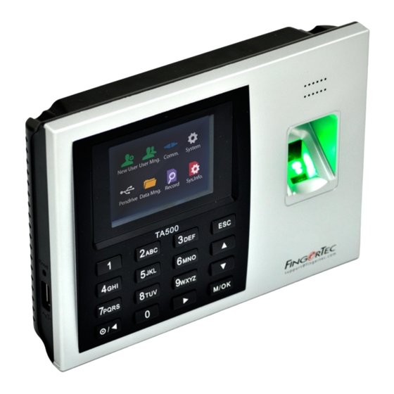
TA500
1
2
ABC
3
DEF
ESC
4
GHI
5
JKL
6
MNO
7
PQRS
8
TUV
9
WXYZ
0
Setting Up Data Communication
/
M/OK
s u p p o r t @ f i n g e r t e c . c o m
(Skip this step if you are using USB flash disk to transfer data)
TCP/IP – LAN Connection
For TCP/IP connection, plug the special RJ45 jack into the TCP/IP
(LAN) Port of the terminal. Connect the other end (normal RJ45 jack)
to the local area network hub or a PC. Configure the device ID, IP ad-
dress, subnet mask and Gateway in the terminal (refer to the hard-
ware user manual for details).
TA500
2
3
1
ESC
ABC
DEF
5
6
GHI
JKL
MNO
8
9
PQRS
TUV
WXYZ
/
0
M/OK
s u p p o r t @ f i n g e r t e c . c o m
........
TCP/IP PORT
Advertisement
Table of Contents

Related Manuals for FingerTec TA500


Summary of Contents for FingerTec TA500
-
Page 1: Installation Guide
@ f i n g e r t e c . c o m Installation Guide • FingerTec offers flexi-kit for all its time attendance models. Attach Avoid installing the terminals in locations prone to high moisture the terminal on the flexi-kit for convenience. - Page 2 The AdapTec Plus is a 12VDC power supply inclusive of a 110~240VAC switching linear power. The AdapTec supplies 12VDC power to the 70mm FingerTec terminal and door lock system as well as charges a 12VDC 68mm 7.0Ah backup battery simultaneously. During an event of a power failure, the back up battery automatically provides power to the terminal and maintains the door lock system.The AdapTec Plus also...
Need help?
Do you have a question about the TA500 and is the answer not in the manual?
Questions and answers