
Related Manuals for Toa MX-628


Summary of Contents for Toa MX-628
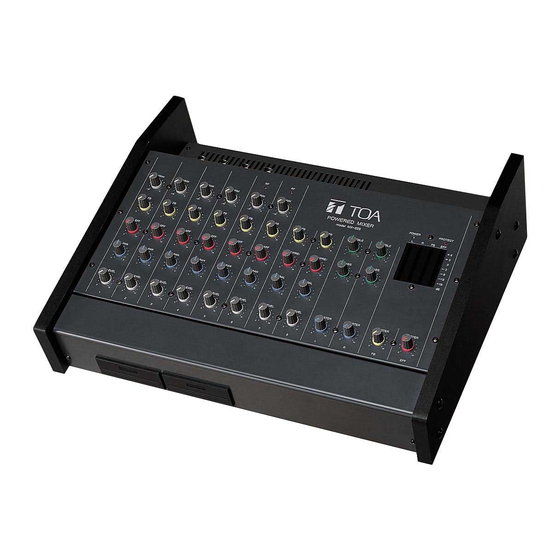
- Page 1 INSTRUCTION MANUAL POWERED MIXER MX-628 Please follow the instructions in this manual to obtain the optimum results from this unit. We also recommend that you keep this manual handy for future reference.
-
Page 2: Table Of Contents
TABLE OF CONTENTS 1. SAFETY PRECAUTIONS ................3 2. GENERAL DESCRIPTION ................4 3. FEATURES ......................4 4. NOMENCLATURE AND FUNCTIONS Operation Panel Channel control section ..................5 Master output control section ................6 Output level indicator section ................6 Input and Output Panels Input panel section .................... -
Page 3: Safety Precautions
AC outlet and shock. contact your nearest TOA dealer. Make no further • When moving the unit, be sure to remove its power attempt to operate the unit in this condition as this supply cord from the wall outlet. -
Page 4: General Description
2. GENERAL DESCRIPTION TOA's MX-628 Powered Mixer is small in size, and comes with 8-channel inputs, 1-channel line output L and R, 1 foldback output and 1 effector output. It also has 2 channels (Speaker output L and R) of built-in power amplifiers with rated output power of 60 W (4 Ω). -
Page 5: Nomenclature And Functions
4. NOMENCLATURE AND FUNCTIONS [Operation Panel] Channel control section Output level indicator section Master output control section Wireless tuner receptacle (Channel 5) Wireless tuner receptacle (Channel 6) Channel control section 1. Trim Control [TRIM] Adjusts a trim, and the output level of panning Adjusts the amplifier gain depending on the potentiometer, sound volume, effector, and foldback microphone input level. -
Page 6: Master Output Control Section
4. Pan-pot [PAN] 9. Master Control [MASTER] Adjusts proportion of a microphone input signal to Adjusts each output master level. be assigned to both the L and R channels. Rotating Note the knob clockwise enhances R channel, and Recording output is not influenced by the Master rotating the knob counterclockwise enhances L Control setting. -
Page 7: Input And Output Panels
[Input and Output Panels] Input panel section 13. Microphone Input Terminals 1 – 6 [MIC1 – MIC6] Phone plug (balanced type) (XLR-3-31/its equivalent or phone jack) Input terminals 1 – 6 are connected to the unit's channels 1 – 6, respectively. These terminals permit connection of various sound sources GROUND COLD ranging from microphones to line-signal level... -
Page 8: Output Panel Section
This terminal is for signal grounding. control. Therefore, decrease the output level control of equipment connected to Channels 7 25. Voltage Selector (MX-628 LH only) and 8 to avoid signal distortion. Sets the selector to either 115 V or 230 V depending on your local power source. -
Page 9: Connection Example
5. CONNECTION EXAMPLE Recorder (cassette deck, etc.) Effector (reverb, etc.) Power amplifier Wireless system antenna Speaker (for foldback) Wireless system antenna AC mains Speaker Sound source (CD player, etc.) Power amplifier Dynamic microphone Speaker Power amplifier Speaker (4 – 16 Ω each) Wireless microphone (Can be used only when a wireless tuner is installed... -
Page 10: Wireless Tuner Installation
Note: Neither the WTU-870 unit nor the WTU-840 unit can be used. If used, the MX-628 may fail. Step 1. Place the unit's Power Switch in the OFF position. -
Page 11: Connected Equipment Selection
7. CONNECTED EQUIPMENT SELECTION Bear the following points in mind when selecting external equipment to be connected to the unit. • Note the impedances of the unit and external equipment. It is generally said that by making the output impedance of signal transmitting equipment equal to the input impedance of signal receiving equipment (impedance matching) or by making the impedance of the transmitting equipment low and the impedance of the receiving equipment high, the trouble that could arise when making connections between equipment can be avoided. -
Page 12: Proper Sound Mixing
8. PROPER SOUND MIXING • When connecting the unit to external equipment, check the input and output levels and impedances of both units carefully before connecting. Note that incorrect connections not only worsen mixing operability, but also adversely affect the sound quality. •... -
Page 13: Block/Level Diagram
9. BLOCK/LEVEL DIAGRAM... -
Page 14: Characteristic Diagram
10. CHARACTERISTIC DIAGRAM Distortion (power amplifier) Power band width (power amplifier) f=1 kHz 1% distortion Frequency (Hz) Output Power (W) Equalizer characteristics 0 dB=1 V BASS MAX TREBLE MAX TREBLE MIN BASS MIN Frequency (Hz) 11. DIMENSIONAL DIAGRAM [Top] [Side] Unit: mm 150.5... -
Page 15: Specifications
12. SPECIFICATIONS Power Source LH Version: 115 V AC or 230 V AC (selectable), 50/60 Hz ER AS Version: 230 V AC, 50/60 Hz Power Consumption 280 W (rated output) 60 W x 2, 4 Ω [0.5% THD (1 kHz)] Rated Output Frequency Response 20 Hz –...
Need help?
Do you have a question about the MX-628 and is the answer not in the manual?
Questions and answers