Table of Contents
Advertisement
Quick Links
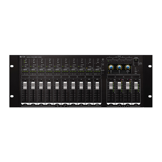
DIGITAL STEREO MIXER
Thank you for purchasing TOA's Digital Stereo Mixer.
Please carefully follow the instructions in this manual to ensure long, trouble-free use of your equipment.
D IG
IT A
P E
L
A K
S T
E R
0 d
B
E O
M IX
-4 0
d B
E R
P E
A K
M -
8 6
L O
0 d
4 D
B
W
C U
T
-4 0
F B
S
d B
P E
A K
T O
N E
A S
/G A
L O
0 d
W
B
S IG
IN
C U
N
T
F B
-4 0
S
d B
P E
A K
T O
1
A S
N E
/G A
L O
0 d
W
B
2
S IG
IN
C U
N
T
3
F B
-4 0
4
S
d B
P E
A K
T O
N E
1
A S
0 d
/G A
L O
S IG
W
B
2
IN
C U
N
T
3
F B
-4 0
1
d B
4
S
P E
A K
1 0
T O
N E
1
A S
L O
0 d
/G A
2
S IG
W
B
IN
C U
9
3
N
T
F B
-4 0
2
S
d B
4
P E
A K
8
1 0
T O
1
N E
A S
L O
0 d
/G A
2
S IG
W
B
IN
C U
7
9
3
N
T
-4 0
F B
3
S
d B
4
P E
6
8
T O
1 0
1
N E
A S
L O
0 d
/G A
5
2
S IG
IN
W
7
C U
N
9
3
T
-4 0
F B
4
S
4
4
6
8
T O
1 0
1
N E
3
A S
/G A
L O
5
2
S IG
IN
7
N
9
3
5
F B
2
4
4
6
8
T O
1 0
1
3
A S
5
2
S IG
7
9
3
2
6
4
4
6
8
1 0
1
3
5
2
7
9
2
7
4
6
8
1 0
3
5
7
9
2
8
4
6
8
1 0
3
5
7
9
2
4
6
8
3
5
7
2
4
6
3
5
2
4
I
3
N
2
P
U
T
OPERATING INSTRUCTIONS
A K
B
d B
P E
A K
0 d
B
W
C U
L
T
-4 0
S
R
d B
P E
A K
N E
/G A
0 d
B
IN
S T
2
N
L
IN P
M O
-4 0
U T
1
N O
R
d B
T O
A S
N E
/T R
S IG
IM
2
N
P R
3
M O
4
N O
A R
E S
C
E T
T O
1 /S
N E
A S
T 2
/T R
3
S IG
IM
N
3
4
1 /S
R E
4
T 2
C O
U T
3
S T
1
4
P O
1 0
W E
B A
S S
R
9
G A
S T
IN
2
V O
8
L
1 0
M ID
7
9
P A
D
V O
6
8
L
O N
R E
5
1
O F
7
B L
P H
F
A N
E
T O
R U
4
1 0
N
M
6
V O
P E A
K
L
3
L O
9
C K
5
+ 1 2
2
R E
2
M O
8
4
+ 6
1 0
T E
P E A
L O
C A
7
K
3
0
L
9
+ 1 2
3
6
2
-6
8
+ 6
1 0
5
-1 2
P E A
7
K
0
9
-2 4
+ 1 2
4
4
6
-6
-4 0
8
+ 6
1 0
3
5
-1 2
P E A
K
d B
7
0
2
9
-2 4
4
+ 1 2
6
-6
8
-4 0
+ 6
3
5
-1 2
7
d B
0
2
4
-2 4
6
-6
-4 0
3
5
-1 2
d B
2
-2 4
4
-4 0
3
d B
2
O
U
T
P
U
T
M-864D
Advertisement
Table of Contents

Related Manuals for Toa M-864D


Summary of Contents for Toa M-864D
-
Page 1: Operating Instructions
+ 1 2 -4 0 -1 2 -2 4 -4 0 -1 2 -2 4 -4 0 Thank you for purchasing TOA’s Digital Stereo Mixer. Please carefully follow the instructions in this manual to ensure long, trouble-free use of your equipment. -
Page 2: Table Of Contents
TABLE OF CONTENTS 1. IMPORTANT SAFETY INSTRUCTIONS ........... 4 2. SAFETY PRECAUTIONS ................5 3. GENERAL DESCRIPTION ................7 4. FEATURES ......................7 5. HANDLING PRECAUTIONS ..............7 6. INSTALLATION PRECAUTIONS ............. 7 7. NOMENCLATURE AND FUNCTIONS ..........8 Front ..........................8 Rear terminal section .................... - Page 3 24.2. Operation ......................48 24.3. Connection ......................50 25. BLOCK DIAGRAM ..................54 26. DIMENSIONAL DIAGRAM ..............55 27. SPECIFICATIONS ..................56 27.1. M-864D ......................56 27.2. ZM-9011 ......................58 27.3. ZM-9012 ......................59 27.4. ZM-9013 ......................59 27.5. ZM-9014 ......................60...
-
Page 4: Important Safety Instructions
1. IMPORTANT SAFETY INSTRUCTIONS • Read these instructions. • Keep these instructions. • Heed all warnings. • Follow all instructions. • Do not use this apparatus near water. • Clean only with dry cloth. • Do not block any ventilation openings. Install in accordance with the manufacture's instructions. • Do not install near any heat sources such as radiators, heat registers, stoves, or other apparatus (including amplifiers) that produce heat. • Do not defeat the safety purpose of the polarized or grounding-type plug. A polarized plug has two blades with one wider than the other. A grounding type plug has two blades and a third grounding prong. The wide blade or the third prong are provided for your safety. If the provided plug does not fit into your outlet, consult an electrician for replacement of the obsolete outlet. • Protect the power cord from being walked on or pinched particularly at plugs, convenience receptacles, and the point where they exit from the apparatus. -
Page 5: Safety Precautions
AC outlet and contact your nearest TOA dealer. Make no further • When unplugging the power supply cord, be sure attempt to operate the unit in this condition as this to grasp the power supply plug;... - Page 6 · The supplied rack-mounting screws can be used cleaning or leaving the unit unused for 10 days or for the TOA equipment rack only. Do not use them more. Doing otherwise may cause a fire or electric for other racks.
-
Page 7: General Description
• The supplied power supply cord is designed for exclusive use with this unit. Never use it with other equipment. • Install the unit in locations where the temperature is between 0 and +40 °C (32 and 104°F) and the moisture is less than 90% (no dew condensation must be formed). • The M-864D is a precision audio component. To prevent failure, avoid locations where the unit may be exposed to strong shocks or vibrations. • To clean, be sure to first switch off the unit's power, then wipe with a dry cloth. When the unit gets very dirty, use a cloth damped in a neutral cleanser. Never use benzene, thinner, alcohol, or chemically-treated cleaning... -
Page 8: Nomenclature And Functions
7. NOMENCLATURE AND FUNCTIONS [Front] Section B Section C Section A • Section A 7 8 9 10 11... - Page 9 Set the operations to be prohibited using the signal level. supplied M-864D PC Software. Output level indicates the post-fader level value. The M-864D is allowed to prohibit all the target Decrease the volume level when the PEAK functions by the factory default. indicator remains lit.
- Page 10 (16) and Assignment switch (19) settings. Cutoff frequency: 100 Hz* 21. Input name label attaching space * It can be adjusted in the range of 20 Hz to 20 kHz using the supplied M-864D PC Software. Affix the label with the printed input name. (See the M-864D Software instructions.) 22. Monaural input volume fader [INPUT 1 – 8] 17. Feedback Suppressor switch and Feedback Adjusts the monaural input volume level.
- Page 11 • Section C 23. Input level indicators [–40 dB, 0 dB, PEAK] 26. Assignment switches (Stereo) and Assignment (Green, red) indicators [1 – 4] (Green) Light green depending on the input signal level. Used to select the output destination of the post- (The peak indicator lights red.) Input level indicates fader signals adjusted using the stereo input the pre-fader level value.
-
Page 12: Rear Terminal Section
LAN cable. Perform function assignment to each contact by a The MX-864D’s default IP address is “192.168.14.1.” PC using the supplied M-864D PC Software. Perform settings by a PC using the supplied M-864D PC Software. 35. Contact input terminals [INPUT C, 1, 2, 3, 4, 5, •... -
Page 13: System Configuration Example
(6) when the control mode is the Gain A, B, C] control mode. –10 dB*, 10 kΩ, unbalanced type, RCA jack. (See p. 54, "BLOCK DIAGRAM.") * 0 dB = 0.775 V 8. SYSTEM CONFIGURATION EXAMPLE The M-864D can be used alone or in conjunction with a PC and external control device. • Using the M-864D unit in conjunction with a PC M-864D Switching hub • Using the M-864D unit in conjunction with the ZM Remote controller M-864D ZM Remote controller • Using the M-864D unit in conjunction with the external control device... - Page 14 • Using the M-864D in conjunction with the external control device via LAN (Ethernet) M-864D Switching hub External control device • Using multiple M-864D units (up to 5 M-864D units) In this event, Preset memory switching interlocks among up to 5 M-864D units. M-864D Switching hub • Using multiple M-864D units (up to 5 units) in conjunction with the external control device and ZM Remote controller to be directly connected, and a PC and external device via LAN.
-
Page 15: Assignment Settings
Assignment indicator Assignment switch Assignment switch M-864D 9.1. Assignment Switches of Inputs 1 through 8 It is possible to assign each monaural input to Outputs 1 through 4. Pressing the Assignment switch 1 causes the corresponding indicator to light, routing the input signal to the OUTPUT 1. -
Page 16: Assignment Switches Of Inputs St1 And St2
(Outputs the mixed signal of MONO INPUTs 1 and 3) REC OUT R* (Outputs the mixed signal of MONO INPUTs 1 and 2) Set the REC OUT assignment using the supplied M-864D PC Software. The REC OUT default assignment is as follows. REC OUT L: Assignment switch 1 REC OUT R: Assignment switch 2 9.2. -
Page 17: Phantom Power, Pad, And Gain Settings
The input sensitivity and phantom power ON or OFF can be set to Monaural inputs 1 through 8 depending on the devices to be connected. Perform these settings by the control knobs after placing the M-864D in Gain control mode. 10.1. Setting Procedures Step 1. -
Page 18: Setting Methods
Phantom power ON (Default setting) Note Turn the phantom power ON only when connecting a microphone which requires phantom power. With the phantom power ON, connecting the device not requiring phantom power may cause the M-864D and this connected device to fail. - Page 19 10.2.3. PAD ON/OFF setting The PAD ON or OFF can be set to Monaural inputs PAD ON/OFF setting knob 1 through 8. When the input level is high, turn on the PAD. The attenuation circuit of the input level is activated by turning on the PAD, eliminating the input clip.
-
Page 20: Trim Control
If the input devices’ output levels are uneven among them, this function serves to align the input levels. Each of A, B, and C inputs provided at the Stereo inputs 1 and 2 can be individually adjusted. Step 1. Place the M-864D in Trim control mode. Press several times the Tone/Trim selection switch of the Stereo input channel for which input level is to be adjusted until the Tone/Trim control mode indicator lights orange. -
Page 21: Tone Control
12. TONE CONTROL It is possible to adjust sound tone of Monaural inputs 1 through 8 and Stereo inputs 1 and 2. Step 1. Place the M-864D in Tone control mode. 1-1 When adjusting monaural inputs 1 through 8 Press the Tone/Gain selection switch of each monaural input several times until the Tone/Gain control mode indicator lights green. -
Page 22: Low Cut Filter Setting
–15 to +15 dB in 1 dB steps (TREBLE) GAIN: 0 dB Note Filter settings other than described above can be performed using the supplied M-864D PC Software. For details, read the M-864D Software instruction. The figures below show the relationship between the setting value indicators around the control knob and the gain. (Common to BASS, MID, and TREBLE) –15 dB –1 dB... -
Page 23: What Is A Low Cut Filter
The cut-off frequencies of the M-864D’s low cut filter are as follows. Default value 100 Hz Variable* 20 Hz to 20 kHz * Adjustable only using the supplied M-864D PC Software. 13.2. Low Cut Filter Setting 13.2.1. Turning ON the low cut filter Press the Low cut switch while the Low cut indicator remains unlit. The Low cut indicator lights, and the Low cut filter turns ON. -
Page 24: Using The Summing Output
(Outputs the mixed L+R signals of STEREO INPUT 1) REC OUT R* (Outputs the mixed L+R signals of STEREO INPUT 1) Set the REC OUT assignment using the supplied M-864D PC Software. The REC OUT default assignment is as follows. REC OUT L: Assignment switch 1... -
Page 25: Volume Level Adjustment
Each volume level of inputs and outputs can be adjusted in the following 4 methods. (a) Adjustment by the front panel mounted faders (b) Adjustment using the supplied M-864D PC Software (c) Adjustment by the optional ZM Remote controller (d) Adjustment by the external control device The configuration of these volume controls is as shown below. -
Page 26: Adjusting The Recording Output (Rec Out) Volume Level
15.1.2. Adjustment using the supplied M-864D PC Software The volume level can be adjusted using the supplied M-864D PC Software. For details, read the separate Software instructions. 15.1.3. Adjustment by the optional ZM Remote controller The volume level can be remotely controlled by the ZM Remote controller. - Page 27 [Adjusting the volume level] Step 1. Press the Recording output switch (REC OUT). Note: Use a fine-tipped object to press in the switch. Each indicator status changes as follows. • Recording output indicator: Lights green. • Trim control mode indicator: Lights orange. • Setting value indicators around the control knob: All indicators flashes twice, then the indicators around the L and R channels knobs indicate each corresponding output level. Flashes twice (Example) Step 2. Adjust the recording output volume level with the control knob. Default value 0 dB Setting range –∞, –44 to +10 dB (in 1 dB steps) The figures below show the relationship between the setting value indicators around the control knob...
-
Page 28: Fbs Function Settings
The FBS function set to each channel of the MONO INPUTs 1 – 8 operates independently. Note The function can also be set using the supplied M-864D PC Software. For details, read the separate Software instructions. Step 1. Press the FBS switch when the Feedback suppressor indicator remains unlit. FBS switch... -
Page 29: Disabling The Fbs Function
17.3. Disabling the FBS Function Step 1. Press the FBS switch while the Feedback FBS switch suppressor indicator is lighting. Feedback suppressor indicator Step 2. Release the FBS switch when the Feedback suppressor indicator goes off. When the Feedback suppressor indicator goes off, Unlit the FBS function is disabled. -
Page 30: Enabling The Arc Function
Be sure to connect the measuring microphone to the MONO INPUT 1. MONO INPUT 1 2-2. Set the input sensitivity. Place the M-864D in Gain control mode, then perform settings to match the type of microphone to be used. (See p. 17.) Dynamic microphone: PAD OFF... - Page 31 • Hold the microphone about 7 cm (3”) from the mouth. Speak at a normal voice level. • Sound is not output from the speakers at this stage as the output amplifier’s volume knob is set to the minimum position. Lights green. M-864D Adjust the MONO INPUT 1’s gain if the indicators are in the status below. (See p. 25.) Lights red. Do not light. Input level is too low. Input level is too high.
- Page 32 Location of the microphone: About the center of the room Step 7. Conduct the ARC measurement. Hold down the ARC switch for 3 seconds or more, then release it when the ARC operation indicator begins to flash. ARC measurement in progress Unlit Flashing ARC operation indicator Note ARC switch Use a fine-tipped object to press in the ARC switch. Hold down for 3 seconds or more. M-864D...
- Page 33 Notes • To stop the ARC measurement partway, press the ARC switch. • Never operate the switches and knobs of the M-864D and the external equipment during the ARC measurement. [ARC measurement operation] A 3-stage operation shown below is performed during the ARC measurement. Different tones sound in each operation stage. The ARC operation indicator flashes slowly during normal measurement, but it begins to flash rapidly when a failure occurs. Measurement progresses normally A failure occurs ARC operation indicator status...
-
Page 34: Example Of The Arc Function Use To Make Fine Acoustic Adjustment
18.4. Example of the ARC Function Use to Make Fine Acoustic Adjustment When wishing to make finer acoustic adjustment, it is possible to set the different ARC filters to the individual output channels. [Setting example in a gymnasium where the M-864D’s output channels are assigned as follows] Cable wiring example OUTPUT 1 and OUTPUT 2 • OUTPUT 1 and 2 channels: Speakers installed at both sides of the stage channels • OUTPUT 4 channel:... -
Page 35: Confirming The Arc Function Setting Status
18.5.2. Confirming the setting status through the ARC switch operation When the ARC operation indicator is lighting, the ARC filter-set output channel can be checked through the ARC switch operation. Hold down the ARC switch for 1 second or more. All the output level indicators of the ARC filter-set output channel flash. Note ARC operation indicator Use a fine-tipped object to Output level indicator press in the ARC switch. ARC switch Hold down for 1 second or more. M-864D All indicators flash... -
Page 36: Disabling The Arc Function
Flashing Unlit ARC operation indicator Assignment switch Assignment switch Hold down for 8 seconds. M-864D Note: Use a fine-tipped object to press in the Assignment switch and the ARC switch. Step 1. Turn off all the Assignment switches 1 – 4 of MONO INPUT 1 (assignment indicators go off). Step 2. Hold down the ARC switch for 8 seconds. The ARC operation indicator flashes rapidly after 3 seconds. Continue to hold it down for 5 seconds. The ARC operation indicator goes off and the ARC function is disabled. -
Page 37: Automatic Mute Setting
19. AUTOMATIC MUTE SETTING This function can only be set using the supplied M-864D PC Software. For details, read the separate Software instructions. 19.1. What is the Automatic Mute Function? It is a function that automatically attenuates the volume level of the signal input to the STEREO INPUTs 1 and 2 by detecting signals input from the MONO INPUTs 1 through 8. -
Page 38: Preset Memory Settings
20.1. Preset Memory Settings Four patterns* of Preset memories can be stored and recalled by the front panel mounted Preset memory key. * Using the supplied M-864D PC Software allows up to 16 Preset memory keys patterns to be stored and recalled through PC operation. -
Page 39: Recalling The Preset Memory
• ARC filter settings • PC VOL* • EXT VOL* • Automatic mute settings* * Settings available only using the supplied M-864D PC Software. The front panel-mounted fader values are not stored. 20.3. Recalling the Preset Memory Step 1. Press the Preset memory key corresponding to the desired Preset memory number. -
Page 40: System Lock Setting
Use the supplied M-864D PC Software to set the System lock function. 21.1. Enabling the System Lock Function Step 1. Set the functions to be locked using the supplied M-864D PC Software. Note All the functions below can be locked by default. -
Page 41: Installation
N E/ G AI S IG -4 0d N E/ G AI S IG -4 0d TOA, be sure to use the screws with a diameter of N E/ G AI S IG -4 0d N E/ G AI S IG... -
Page 42: Connections
Use the AD-246 AC adapter (optional) or its equivalent. As for the usable adapter, consult your TOA dealer. The M-864D can communicate with the external equipment via LAN. As the M-864D has a function to send the control command to the AV switcher, it can control the AV switcher without using control devices such as the AMX. -
Page 43: Removable Terminal Plug Connection
23.2. Removable Terminal Plug Connection Notes • Avoid soldering stranded or shielded cable, as contact resistance may increase when the cable is tightened and the solder is crushed, possibly resulting in an excessive rise in joint temperatures. • When connecting 2 cables or a shielded cable to a single terminal, use a ferrule terminal with an insulation sleeve to crimp the cables because such cable conductors could become loose. Recommended ferrule terminals for signal cables (made by Phoenix Contact) Unit: mm (in) Insulation sleeve... -
Page 44: When Using The Zm Remote Controller
24.1. General Description of the ZM Remote Controller 24.1.1. ZM-9011 Remote Control Panel The ZM-9011 performs various controls with the 4 buttons in connection to the M-864D. Communication is executed between the M-864D and ZM-9011, and the indicator status changes depending on the M-864D’s operation. - Page 45 5. 24 V DC terminals Connect the power cable from the M-864D. 24.1.2. ZM-9012 Remote Control Panel The ZM-9012 performs volume control of the assigned input/output channel with the volume control knob in connection to the M-864D, and also indicates the volume set position of the assigned channel. It can be mounted in one-gang electrical box. [Front] [Side] 1.
- Page 46 24.1.3. ZM-9013 Remote Control Panel The ZM-9013 performs various controls with the 8 buttons in connection to the M-864D. Communication is executed between the M-864D and ZM-9013, and the indicator status changes depending on the M-864D’s operation. It can be mounted in two-gang electrical box.
- Page 47 24.1.4. ZM-9014 Remote Control Panel The ZM-9014 performs various controls with the 4 buttons in connection to the M-864D. It also performs volume control of the assigned input/output channel with the volume control knob in connection to the M-864D, and also indicates the volume set position of the assigned channel. It can be mounted in two-gang electrical box.
-
Page 48: Operation
For example, when the recall function of Preset memory No. 1 has been assigned to the Function button, if the Present memory No. 2 is recalled through the M-864D’s front key operation, the indicator at the Function button goes off. - Page 49 24.2.2. Volume Control Operation It is possible to increase or decrease the Crosspoint gain and the external volume levels of the Monaural inputs 1 through 8, Stereo inputs 1 and 2, Monaural output 1 through 4, and Recording output. [Operating the ZM-9012] The channel for which volume is to be controlled is assigned in advance.
-
Page 50: Connection
24.3. Connection • When connecting the ZM Remote controller, connect the data bus and power line for the RS-485 communication. Use the removable terminal plug for connection. (See p. 43, "Removable Terminal Plug Connection.") • Connect the dedicated AC adapter or its equivalent* to the M-864D to supply power to the ZM Remote controller. Each one AC adapter is required for the LINK A and LINK B separately. • Up to 8 ZM Remote controllers can be connected to each channel. - Page 51 Perform wiring installation so that the total cable length between the M-864D and each ZM Remote controller does not exceed 800 m (870 yd). Example: Up to 16 ZM Remote controllers can be connected if the total cable length between the M-864D and each ZM Remote controller is within 800 m (870 yd).
- Page 52 Example 1: When the cable length of each channel is 200 m (210 yd) regardless of the distance between the M-864D and ZM Remote controller and also between individual ZM Remote controllers, up to 16 ZM Remote controllers can be connected. (Total cable length: 400 m or 435 yd)
- Page 53 Example 3: When the cable length of each channel is 400 m (435 yd) regardless of the distance between the M-864D and ZM Remote controller and also between individual ZM Remote controllers, up to 12 ZM Remote controllers can be connected. (Total cable length: 800 m or 870 yd)
-
Page 54: Block Diagram
25. BLOCK DIAGRAM... -
Page 55: Dimensional Diagram
26. DIMENSIONAL DIAGRAM Unit: mm (in) (Viewed from the direction “A”) 482.6 (19) 465.6 (18.33) 140 (5.51) 420 (16.54) -
Page 56: Specifications
27. SPECIFICATIONS 27.1. M-864D Version CE/CE-GB CE-AU Power Source 220 – 240 V AC, 50/60 Hz 220 – 240 V AC, 50 Hz 100 – 120 V AC, 60 Hz Power Consumption 30 W Frequency Response 20 Hz – 20 kHz, ±1 dB Sampling Frequency 48 kHz Dynamic Range 100 dB or more Distortion 0.03 % or less, 1 kHz, +4 dB* input/output, 20 Hz − 20 kHz BPF Crosstalk −80 dB or less, 1 kHz Input Monaural input, 8 channels, removable terminal block (3 P) - Page 57 Connection cable: Shielded Cat. 5 or higher twisted pair cable for LAN (Cat. 5-STP or better) Maximum cable length: 100 m or 110 yd (between M-864D and switching hub) Operating Temperature 0 to 40 ºC (32 to 104 ºF) Operating Humidity...
-
Page 58: Zm-9011
Allows side-by-side two fader knobs to be linked and operated together as one fader. • Optional products Remote control panel: ZM-9011/9012/9013/9014 AC adapter: AD-246* Consult your TOA dealer when using an equivalent adapter. 27.2. ZM-9011 Power Source 24 V DC (supplied from M-864D) Current Consumption... -
Page 59: Zm-9012
27.3. ZM-9012 Power Source 24 V DC (supplied from M-864D) Current Consumption 50 mA or less Terminal Removable terminal block (10 pins) Connection Cable Shielded CPEV cable (paired data line and paired power line) or Category 5 twisted pair cable for LAN (CAT5-STP) -
Page 60: Zm-9014
Modifications Any modifications made to this device that are not approved by TOA Corporation may void the authority granted to the user by the FCC to operate this equipment.
Need help?
Do you have a question about the M-864D and is the answer not in the manual?
Questions and answers