
Related Manuals for Toa MX-101


Summary of Contents for Toa MX-101
- Page 1 All manuals and user guides at all-guides.com Operating instruction Manual POWERED MIXER Model MX-101 Toa Electric Co., Ltd. KOBE, JAPAN...
-
Page 2: Table Of Contents
The pin 1 is ground (shield), the pin 2 cold (low, minus), the pin 3 hot (high,plus). 2. Description of components and functions on the MX-101. Various descriptions are applied, depending on each manufacturer. In our Operating and Instruction Manual explanation of components and func- tions is made according to our usage for them. -
Page 3: General Description
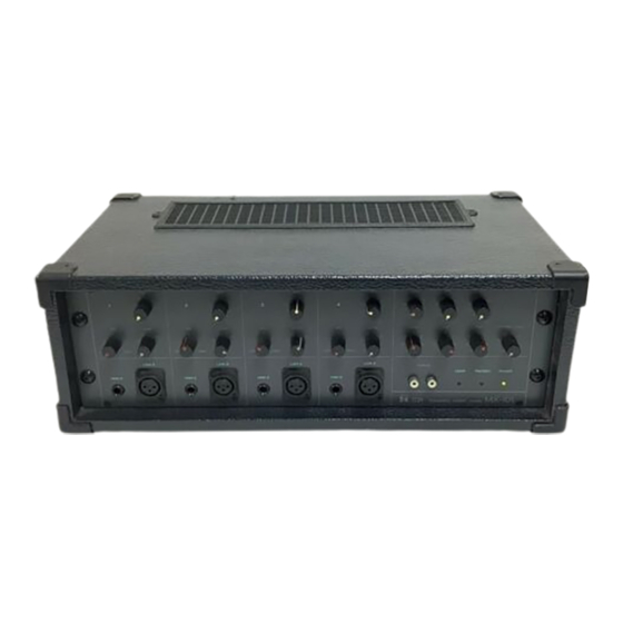
All manuals and user guides at all-guides.com General Description The TOA MX-101 is a very compact, four channel self-powered mixer. It was designed to deliver maximum features and performance in a cost-effective portable PA package. The MX-101 features four input channels, one main system output, and one personal monitoring (foldback) output. -
Page 4: Front Panel (Names Of Components & Their Usage)
The compressor is pro- High Impedance Connectors MX-101 should be checked. If vided to protect speaker sys- (HIGH Z) the LED remains lighted, the tems by compressing the input... -
Page 5: Rear Panel (Names Of Components & Their Usage)
4 ohms speaker load. surface ( 4 - 6 inches should do). The vents on the bottom and top of the MX-101 are also provided for convection cool- Power Switch ing. These vents should be kept (POWER) clear and open. -
Page 6: Connection Examples
All manuals and user guides at all-guides.com Connection Examples SPEAKER SYSTEM (Self powered speakers) MAIN SPEAKER SYSTEM for foldback From Speaker Jack From FB OUT Jack on Real Panel on Rear Panel Line Out Low Z input should be connected with low impedance (50 ohm ~ 600 ohm) KEYBOARD microphones... -
Page 7: Input Connections
As is described in the beginning of the Operating Instructions Manual, the connectors of the MX-101 are wired as follows: Pin 1 is ground (shield). Pin 2 is cold (low, minus). Pin 3 is hot (high, plus) -
Page 8: Block And Level Diagrams
All manuals and user guides at all-guides.com Block and Level Diagrams BLOCK DIAGRAMS LEVEL DIAGRAM — 7 —... -
Page 9: Specifications
All manuals and user guides at all-guides.com Specifications MIXER SECTION Frequency Response Maximum Voltage Gain + 1, -3dB 30Hz~20kHz (input LEVEL at "5" position) INPUT to SYSTEM out 64dB INPUT to FB out 64dB Total Harmonic Distortion TAPE to SYSTEM out 14dB 0.05% +4dB* at 1kHz. -
Page 10: Characteristics Diagrams
All manuals and user guides at all-guides.com Characteristics Diagrams HIGH Z IN. & INPUT EQ 3 BAND EQ POWER AMP POWER BAND WIDTH POWER AMP T.H.D. vs POWER OUTPUT POWER AMP COMPRESSOR REVERBERATION FREQUENCY RESPONSE Appearance — 9 —... - Page 11 All manuals and user guides at all-guides.com Toa Electric Co., Ltd. KOBE, JAPAN Printed in Japan 133-02-884-9...
Need help?
Do you have a question about the MX-101 and is the answer not in the manual?
Questions and answers