Table of Contents

Related Manuals for Toa M-633D CE


Summary of Contents for Toa M-633D CE
- Page 1 OPERATING INSTRUCTIONS DIGITAL STEREO MIXER M-633D CE M-633D CE-GB M-633D CE-AU Thank you for purchasing TOA’s Digital Stereo Mixer. Please carefully follow the instructions in this manual to ensure long, trouble-free use of your equipment.
-
Page 2: Table Of Contents
TABLE OF CONTENTS 1. IMPORTANT SAFETY INSTRUCTIONS ..........3 2. SAFETY PRECAUTIONS ................4 3. GENERAL DESCRIPTION ................6 4. FEATURES ......................6 5. HANDLING PRECAUTIONS ..............6 6. NOMENCLATURE AND FUNCTIONS ..........7 Front ..........................7 Rear ..........................8 7. -
Page 3: Important Safety Instructions
1. IMPORTANT SAFETY INSTRUCTIONS • Read these instructions. • Protect the power cord from being walked on or pinched particularly at plugs, convenience • Keep these instructions. receptacles, and the point where they exit from the apparatus. • Heed all warnings. •... -
Page 4: Safety Precautions
AVERTISSEMENT the power supply plug from the AC outlet and contact your nearest TOA dealer. Make no further attempt to operate the unit in this condition as this may cause fire or electric shock. - Page 5 (Every version except the M-633D CU for US) shock. · The supplied rack-mounting screws can be used for the TOA equipment rack only. Do not use them for • When unplugging the power supply cord, be sure to other racks.
-
Page 6: General Description
3. GENERAL DESCRIPTION The M-633D is a stereo mixer with digital signal processing functions such as Automatic Resonance Control function (ARC), Feedback Suppressor function (FBS), Automatic Clipguard function (ACG), and Automatic Mute function (AUTO MUTE). It can be mounted in an EIA component rack (1U size*). * 1U size = 44.5 mm (standard size) 4. -
Page 7: Nomenclature And Functions
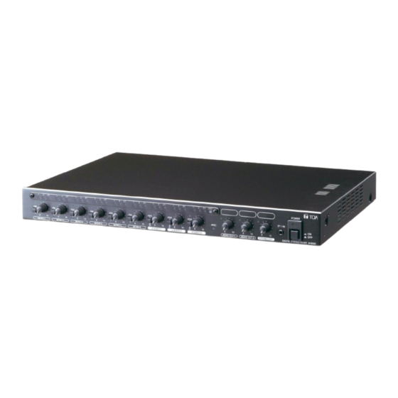
6. NOMENCLATURE AND FUNCTIONS [Front] 1. Power switch 10. Stereo output level control knob Press this switch to turn on the power. To turn off Adjusts the stereo output level. the power, press this switch again. 11. Front-mounted stereo input jack 2. -
Page 8: Rear
[Rear] Do not trash this device into normal waste. Use the foreseen electric waste collection places. This mark is a declaration that this product complies with all applicable EU directive and regulations. This symbol stands for a functional ground terminal. When a audio system produces hum noise, then connecting the ground connections between several audio devices may reduce or eliminate it. -
Page 9: Assignment Settings
7. ASSIGNMENT SETTINGS It is possible to assign each input to 3 output channels individually (MONO 1, MONO 2, and STEREO). Pressing the Assignment switch "1" routes the input signal to the MONO OUT 1 output, switch "2" to the MONO OUT 2 output, and switch "ST"... -
Page 10: Using The Summing Output Keys
8. USING THE SUMMING OUTPUT KEYS It is possible to output the stereo input signals applied to the STEREO 1 – 3 to the stereo "L" and "R" outputs either in stereo mode or monaural mode. Summing output key [When the summing output key is pressed in (MONO position)] Signals applied to each of the input "L"... -
Page 11: Setting The Arc Function
9. SETTING THE ARC FUNCTION 9.1. What is the Automatic Resonance Control (ARC) Function? It is a function that automatically creates a sound field compensation filter (ARC filter) to improve sound clarity by measuring the inherent acoustic characteristics in architectural space. 9.2. - Page 12 9.2.3. How to confirm the ARC enabled channel The output level indicator of the ARC enabled (ARC filter preset) output channel lights orange when the ARC switch is pressed. Light orange. Press briefly, then release. 9.2.4. ARC operation indicator status ARC measurement ARC filter ON ARC filter OFF...
-
Page 13: Enabling The Arc Function
9.3. Enabling the ARC Function Notes • The ARC filter is created on the output channel selected with the Assignment switches at the ARC measurement. • The ARC filter previously set on the output channel will be updated by the newly created ARC filter after the ARC measurement. - Page 14 Step 2. Connect a measuring microphone. The microphone for normal use can be used. 2-1. Connect the microphone to the phone jack or removable terminal block of MONO IN 1/ARC on the rear panel. 2-2. Set the input sensitivity selector switch to the appropriate position depending on the microphone to be connected.
- Page 15 When the indicator lights red Input signal is too big. • Check the position of the input sensitivity selector switch on the unit's rear panel. Try to set the switch to "LINE." Step 4. Select the output channel. Press in the MONO 1’s assignment switch corresponding to the output channel to which the ARC filter is set.
- Page 16 Step 6. Install the measuring microphone. It is recommended to install the microphone as shown below as a guide. [Microphone setting example] Height of the microphone: At the listening position Angle of the microphone: 45 º up Location of the microphone: About the center of the room 45°...
- Page 17 Step 7. Conduct ARC measurement. ARC Switch ARC operation indicator Hold down the ARC switch for 3 seconds. The ARC operation indicator begins to flash and the measurement starts. Hold down for Release when the indicator 3 seconds. begins to flash. Flashes during Unlit the measurement.
- Page 18 Measurement starts. The signals input to the MONO 2 – 6, and STEREO 1 – 3 are muted during measurement. (Only MONO 1's signal is output.) The FBS function and Automatic mute function are temporarily turned OFF. When the ARC operation indicator flashes rapidly soon after measurement starts.* MONO 1 is not assigned to any output.
-
Page 19: Making Fine Acoustic Adjustment
9.4. Making Fine Acoustic Adjustment When finer acoustic adjustment is required, different ARC filters can be set for individual output channels. [Setting example in a gymnasium where the unit's output channels are assigned as follows] Set different ARC filters to the MONO OUT 1 channel and STEREO OUT channel. STEREO OUT channel Cable wiring example •... -
Page 20: Disabling The Arc Function
Step 2. Set ARC filter only to the STEREO OUT channel (Stereo speakers installed at both sides of the stage). Press in (ON). 2-1. Press in only the MONO 1’s assignment switch "ST" to turn it ON. ST: ON 2-2. Turn the output level control knobs as follows. MONO OUT 1: To the "0"... -
Page 21: Setting The Fbs Function
10. SETTING THE FBS FUNCTION 10.1. What is the Feedback Suppressor Function (FBS)? It is a function that the built-in feedback suppressor filter automatically works to suppress acoustic feedback when the feedback occurs. Level Feedback suppressor filter Frequency Feedback frequency 10.2. -
Page 22: Setting The Automatic Mute Function
11. SETTING THE AUTOMATIC MUTE FUNCTION 11.1. What is the Automatic Mute Function (AUTO MUTE)? It is a function that attenuates the signal input to the STEREO 1 through 3 by detecting signals input to the MONO 1 – 6. AUTO MUTE is also called as Ducker. -
Page 23: Automatic Clipguard (Acg) Function
12. AUTOMATIC CLIPGUARD (ACG) FUNCTION It is a function that automatically control input sensitivity to an appropriate value when the broadcast is distorted in the presence of an excessive input signal. For example, the ACG function prevents the broadcast from being made with its sound distorted even if a line level signal is erroneously applied to the MONO IN input set to "MIC."... -
Page 24: Resetting To Factory Default Settings
13. RESETTING TO FACTORY DEFAULT SETTINGS Step 1. Disable the ARC function. (See p. 20.) Step 2. Disable the FBS function. (See p. 21.) Step 3. Turns off the Automatic mute function. Shift the rear-mounted AUTO MUTE switch to the OFF position. Step 4. -
Page 25: Mounting In A Rack
14. MOUNTING IN A RACK Mount the unit in an equipment rack using the supplied rack mounting screws. M-633D Rack mouting bracket (supplied) Machine screw M3 x 8 (supplied) Step 1. Attach the rack mounting brackets to the unit's sides. Rack mouting screw 5 x 12 with washer (supplied*) Step 2. -
Page 26: Connection
15. CONNECTION 15.1. Connection Example Playback devices (such as cassette deck, Microphones CD player, or MD player) Wireless equipment DOWN M-633D Speakers Power amplifier Speakers 15.2. Phantom Power Supply • Set the rear-mounted Input level selector switch to "PHANTOM" position only when connecting a microphone which requires phantom power (+24 V, 10 mA) to the corresponding input terminal. -
Page 27: Removable Terminal Plug Connection
15.3. Removable Terminal Plug Connection Notes • Be sure to use shielded cables for audio signal lines. • Avoid soldering cable conductor, as contact resistance may increase when the cable is tightened and the solder is crushed, possibly resulting in an excessive rise in joint temperatures. [Cable end treatment] Shielded cable 7 mm (0.28”) -
Page 28: Block Diagram
16. BLOCK DIAGRAM Digital Analog SIGNAL MIC (−46 dB) +24 V LINE (−10 dB) PHANTOM (−46 dB) GREEN RED PHANTOM MONO IN 1 POWER −10/−46 dB VOLUME +24 V LINE PHANTOM MONO IN 2 PHANTOM POWER −10/−46 dB +24 V LINE PHANTOM MONO IN 3... - Page 29 Analog STEREO MONO SIGNAL GREEN VOLUME MONO OUT 1 0 dB MONO OUT 2 0 dB ST OUT L 0 dB ST OUT R 0 dB REC OUT L −10 dB REC OUT R −10 dB 0 dB = 1 V [dB] LINE (0 dB) STEREO (0 dB)
-
Page 30: Dimensional Diagram
17. DIMENSIONAL DIAGRAM Unit : mm (in) [Rear] [Front] 483.6 (19.04) 466 (18.35) 420 (16.54) [Side] 341.3 (13.44) 320 (12.6) 20 (0.79) 20 (0.79) 6-M3... -
Page 31: Specifications
18. SPECIFICATIONS Model No. M-633D CE, M-633D CE-GB M-633D CE-AU Power Source 220 – 240 V AC, 50/60 Hz 220 – 240 V AC, 50 Hz Power Consumption 14 W Frequency Response 20 Hz – 20 kHz Sampling Frequency 48 kHz Dynamic Range Over 90 dB (IHF–A weighted) -
Page 32: Accessories
Modifications Any modifications made to this device that are not approved by TOA Corporation may void the authority granted to the user by the FCC to operate this equipment.
Need help?
Do you have a question about the M-633D CE and is the answer not in the manual?
Questions and answers