Advertisement
Quick Links
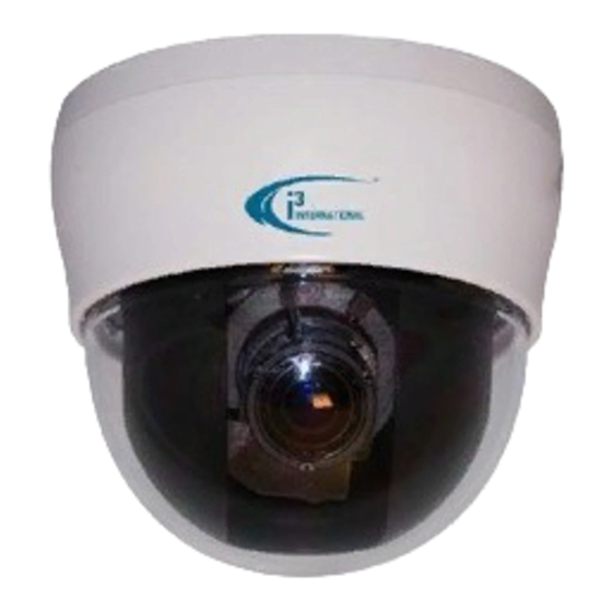
QUICK START GUIDE
Di210 / Di210B Indoor Dome
SAFETY
1. This quick start guide is designed for users who have an
adequate knowledge of network cameras.
2. Do not touch the imaging surface of the sensor. Use a soft
cloth moistened with alcohol to clean the surface if it is
touched accidentally.
3. Ensure the power supply voltage is correct for the particular
variant of camera before operation.
4. Do not attempt to service this camera yourself unless you
are authorized to do so. Opening the camera may expose
you to electrocution or other hazards. Refer all servicing to
qualified personnel only.
5. For more detail on installation and operation, please refer to
CD provided.
PACKAGE CONTENTS
- One fully assembled camera
- Two screw anchors & TP4x15mm
tapping screws
- One 2nd video monitor output cable
INSTALLATION
The dome camera is a fully integrated enclosure with camera
and lens. Figure 3-1 Camera Parts
6
5
- One mounting template
- One TP1.7 screw
- One logo plate
A
B
3-1 Illustration
1. Conduit hole used for surface run
power/video connector
2. bottom case
3. fixed bottom case with camera housing
4. Dome cover
5. Zoom lever
6. Focus lever
A. 24VAC/12VDC power input connector
(red+, black-)
B. Video output connector (BNC)
Please Note: See figure 3-5 for an
explanation of Camera Adjustment Functions
Figure 3-2 Bottom Case Removal
Mounting the camera
1. Place the mounting template (supplied) on the mounting
surface and mark the holes (see Figure 3-3).
2. Drill two holes and then insert the screw anchors into the holes.
3. Take off the camera housing.
4. Secure the bottom case to the wall ceiling with the TP4 x 15 mm
tapping screws.
Please Note: Depending on the type of surface, different type of
screws and anchors may be required.
Figure 3-3 Camera Installation
3-3 Illustration
1. Screw anchors (x2), supplied
2. Mounting template
3. TP4 x 15 tapping screws (x2)
supplied
Removing the bottom case
1. Gently turn the camera housing (#4 on
figure 3-2) counter-clockwise to unlock
and pull free of the bottom case (#1).
2. Gently take off the inner liner (#3) from
the two notches (#2) in the housing (#4).
3. Set the dome (and liner) aside.
3-2 Illustration
1. Bottom case
2. Tilt adjustment bracket and thumb nuts,
notches (x2)
3. Inner Liner
4.Camera housing
Advertisement

Related Manuals for i3 International Di210


Summary of Contents for i3 International Di210
-
Page 1: Quick Start Guide
Figure 3-2 Bottom Case Removal QUICK START GUIDE Di210 / Di210B Indoor Dome Removing the bottom case SAFETY 1. Gently turn the camera housing (#4 on figure 3-2) counter-clockwise to unlock and pull free of the bottom case (#1). 1. This quick start guide is designed for users who have an 2. -
Page 2: Optional Camera Settings
QUICK START GUIDE Di210 / Di210B Indoor Dome Adjust the Camera Position Camera The dome camera has three axes for positioning the camera. While Signal system NTSC monitoring the picture on the monitor, adjust the camera position as Scanning system...