Table of Contents
Advertisement
Advertisement
Table of Contents

Related Manuals for Fimer SYMPLEX 320


Summary of Contents for Fimer SYMPLEX 320
- Page 1 INSTRUCTION MANUAL SYMPLEX 320 SYMPLEX 420 Ed. 2014_11_11 910.100.512GB REV00...
- Page 2 It is user’s responsibility to keep it intact and in good conditions. The manufacturer has the right to apply modifies in every moment or without any forewarning. Every Fimer product is minded, designed and produced in Italy in our sites. This is guarantee of high quality and reliability.
- Page 3 Our production, assistance and training site is exclusively on Italian region and we can praise a 100% MADE IN ITALY. In addition, Fimer has inside a complete chain thanks to an efficient and high quality carpentry department, lines of electronic boards and testing/assembly department which make possible to create the entire product.
- Page 4 SYMPLEX 320 SYMPLEX 420 5T5.321.152 5T5.421.152 MIG-MAG / MMA 3PH MIG-MAG / MMA 3PH 15 - 320 A (MIG-MAG) 15 - 400 A (MIG-MAG) 15 - 300 A (MMA) 15 - 370 A (MMA) Peso Peso 19.8 kg 21.3 kg...
- Page 5 SYMPLEX 320 SYMPLEX 420...
-
Page 6: Table Of Contents
SUMMARY WARNING _________________________________________________________________________________ DEVICE DESCRIPTION _____________________________________________________________________ 2.1 SYMPLEX (MODELS 320-420) FRONT VIEW .......................... 2.2 SYMPLEX (MODELS 320-420) REAR VIEW..........................11 INTERFACE PANEL ________________________________________________________________________ 3.1 CONTROL PANEL DIAGRAM ..............................3.2 CONTROL PANEL DESCRIPTION ............................FUNCTIONING ____________________________________________________________________________ 4.1 EQUIPMENT COOLING ................................4.2 EARTH CABLE ..................................4.3 ELECTRICITY CONNECTION .............................. -
Page 7: Warning
WARNING WARNING SYMBOLS WARNING SYMBOLS DANGER COMPRESSED GAS DANGER Indicating the risk of injury or death in the event of improper hand- (Indicating a hazard that could cause injury or damage) ling or maintenance of compressed gas cylinders or regulators ELECTRIC SHOCK FIRE (Indicating the danger of electric shock) - Page 8 WARNING OVERLOAD PROTECTION SPARE PARTS Use only manufacturer-recommended spare parts. Check that the power source supplying the Welder carries the Other spare parts could cause equipment mal- correct voltage and is safety-protected. The power switch must open all the function. The use of non-original spare parts will also result in the war- ranty provisions becoming null and void, releasing the manufacturer power supply circuits.
-
Page 9: Electric Shock
WARNING DAMAGED GAS CYLINDERS WALL AND FLOOR PROTECTION NEVER use damaged or faulty cylinders. The walls and flooring surrounding the welding CYLINDER RELOCATION environment must be shielded using non-flammable materials. This not only reduces the risk of fire but also avoids damage to the wal- NEVER lift a gas cylinder by holding the regulator. -
Page 10: Device Description
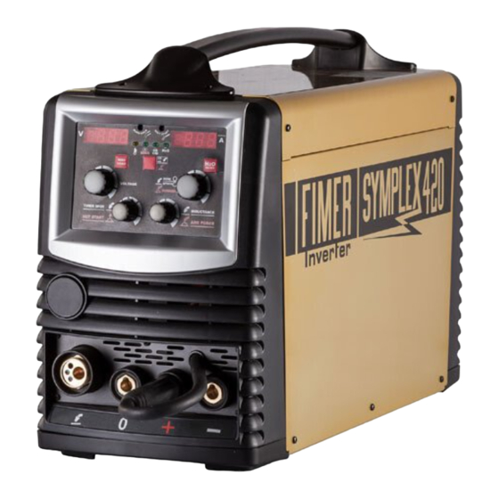
DEVICE DESCRIPTION SYMPLEX (models 320-420) FRONT VIEW REFERENCE DESCRIPTION TRANSPORT HANDLE CONTROL PANEL/INTERFACE MIG/MAG CENTRAL CONNECTION FOR TORCH (EURO) WELDING CURRENT CABLE FOR EURO CONNECTION POLARITY: • MIG/MAG = PLUG IN “ + “ • SELF SHIELDED WIRE = PLUG IN “ - “ •... -
Page 11: Symplex (Models 320-420) Rear View
DEVICE DESCRIPTION SYMPLEX (models 320-420) REAR VIEW REFERENCE DESCRIPTION SAFETY FUSE FOR WATER COOLING UNIT 4A - T 500V 5 POLE SOCKET FOR SUPPLY/SIGNALS WATER COOLING UNIT MAIN SWITCH, MACHINE ON/OFF MAINS CABLE SHIELDING GAS QUICK COUPLING (MIG/MAG) COOLING AIR OUTLET... -
Page 12: Interface Panel
INTERFACE PANEL CONTROL PANEL DIAGRAM Following all the information about control panel model Symplex 320 – Simplex 420 DL17 POT4 POT3 Wire speed Welding Soft Start Burn Back Tacking Inductance (m/min) voltage (V) (m/min) Time (ms) time (s) Chart 1: parameters Simplex320 – Simplex420 in MIG... -
Page 13: Control Panel Description
INTERFACE PANEL CONTROL PANEL DESCRIPTION POS. DESCRIPTION FUNCTION It shows the welding voltage set while during welding process visualizes the voltage measured by the machine. It’s also showed, when modified, the tacking time set. VIEW DISPLAY LEFT On MMA mode it shows the welding voltage measured by the machine. It’s also showed, when modified, the reference parameter of the “Hot Start”... - Page 14 INTERFACE PANEL BURN BACK TIME It allows to change the wire length on top of the torch at the end of TRIMMER REGULATION welding. SOFT START TRIMMER It allows to modify the wire approaching speed to obtain a welding REGULATION trigger softer or speeder.
-
Page 15: Functioning
FUNCTIONING EQUIPMENT COOLING To obtain an optimal duty cycle of the machines please observe the following conditions: • Assure an adequate ventilation in the workplace • Leave open the inflow and outflow openings of the welding machine • Pay attention to avoid metallic parts, powder and other external parts enter into the machine EARTH CABLE Burn danger after inappropriate connection of earth cable! The presence of paint, rust and impurities on connection points prevent current flux and can cause... -
Page 16: Shielding Gas Supply
FUNCTIONING SHIELDING GAS SUPPLY Injuries danger caused by overthrow of the gas protection cylinders! Gas protection cylinders can overturn in case of inadequate fixing and seriously injure people! • Assure the protection gas cylinders by the available protection elements provided on trolleys •... -
Page 17: Mig-Mag Welding
MIG-MAG WELDING 5.1 TORCH PREPARATION Depending on the welding wire diameter and the wire electrode type it has to be used a spiral liner or a plastic/Teflon/graphite liner with an internal diameter adequate to the welding torch and the used wire. Suggestion: •... -
Page 18: Torch And Earth Cable Installation
MIG-MAG WELDING 5.2 TORCH AND EARTH CABLE INSTALLATION • Insert the central connector into the main connection of the welding torch and screw in with hexagon nut • Insert the earth cable connector into welding current grip “-“ (MIG/MAG) “+” (no gas wire) and fix it. •... - Page 19 MIG-MAG WELDING Attention: Before starting the wire installation steps, always remove the gas nozzle/diffuser and the wire guide tip from welding torch. Disconnect the electrical supply cable. Unscrew the knob placed at the center of Eventually remove the spacer depending Remove the plastic protection of new roll on the roll’s dimensions.
-
Page 20: Rolls Replacement
MIG-MAG WELDING 5.4 ROLLS REPLACEMENT Danger of injuries due to welding wire escaping from welding torch! • Welding wire can quickly escape from welding torch and cause injuries to face, eyes and other body parts! • Never point the welding torch to Yourself or to other persons! •... -
Page 21: Function 2T
MIG-MAG WELDING 5.5 FUNCTION 2T STEP 1 • Press and hold on torch trigger. • Shielding gas is out of the torch (gas pre-flow). • Wire feeder motor runs at “soft start speed”. • Arc ignites after the wire electrode makes contact with the workpiece, the welding current flows. •... -
Page 22: Function 4T
MIG-MAG WELDING 5.6 FUNCTION 4T STEP 1 • Press and hold on torch trigger. • Shielding gas is out of the torch (gas pre-flow). • Wire feeder motor runs at “soft start speed”. • Arc ignites after the wire electrode makes contact with the workpiece, the welding current flows. •... -
Page 23: Mma Welding
MMA WELDING 6.1 CONNECTING THE ELECTRODE HOLDER AND THE EARTH CABLE EXTERNAL ACCESSIBLE LIVE PARTS UNDER VOLTAGE (Negative AND Positive Terminal Fast- Connect Plug). WARNING OF HIGH VOLTAGE ELECTRIC SHOCK INJURY NB: the manufacturer indicates polarity on electrodes’ package NB: special electrode holders and carbon electrodes are necessary for gouging Installation: •... -
Page 24: Alarms/Troubleshooting
ALARMS/TROUBLESHOOTING 7.1 ERROR MESSAGES Here are led signal errors: DESCRIZIONE Short-circuit error “Err. S.C.”. This error can occurs only when the machine is welding in MMA. Changing from MIG modality to MMA modality if the electrode makes contact with the work- piece or with another metal surface, then the short-circuit error appears which prevents inverter starting. - Page 25 ALARMS/TROUBLESHOOTING Undervoltage error “Err. LInE”. This error occurs when the machine measures undervolatge condition. Error solving: The machine will start again automatically to function when the voltage grow up to an uncri- tical value. Thermal overload error “Err. tHr”. This error occurs when the machine is in thermal overload due to an excessive overheat- ing.
-
Page 26: Care And Maintenance
CARE AND MAINTENANCE DAILY MAINTENANCE • Supply cable and its discharge traction • Welding current conductors (verify their locked and tight position) • Gas tubes and their commutation devices (electric valve) • Gas cylinder fixing elements • Use, alert, protection and position devices (functioning control) •... -
Page 27: Service Menu
SERVICE MENU 9.1 SERVICE MENU Our machines have a Service Menu and it is reachable by a combination of buttons. This menu allows to modify some parameters to improve and/or customize Your machine depending on Your needs. 9.2 ENTERING IN SERVICE MENU In the starting phase of the machine, it is necessary to push both wire charge (PU3) button and “2S/4S/ MMA”... -
Page 28: Menu Service Exit
SERVICE MENU (always working) or “AUTO” mode (On when the welding process is On). You will see “PMP” “AUTO” or “ON” on display. Default mode is “AUTO”. • Restore default values: “rES” (reset) script is visualized. By turning the wire speed setting knob it will appear ON”... -
Page 29: Acessories
ACESSORIES 10.1 TROLLEY There are different types of trolley according to the final use: 580.690.008 580.690.005 580.690.007 It provides the installation of Without water cooling system) it provides only the installation water cooling system WCS1 of water cooling system WCS2 (580.520.053) and toolsbox) (580.521.053) - without toolsbox (580.690.100) -
Page 30: Toolsbox
ACESSORIES 10.2 TOOLSBOX You can use the Tools Box only with trolley C7s cod. 580.690.008 and it’s an alternative to the water cooling unit (it isn’t possible to install both accessories under the welding machine). TOOLSBOX 580.690.100 260x680x260 mm 25 kg 10.3 WATER COOLING UNIT (WCS1 - WCS2) Depending on the trolley selected, you can choose the following units of cooling: WCS1... -
Page 31: Accessories
ACESSORIES 10.4 ACCESSORIES DESCRIPTION ITEM NR. KIT CABLE 049.600.055 Cable with earth clamp 25 mm2 - dinse 50 mm2 - 3 m 049.600.056 Cable with earth clamp 35 mm2 - dinse 50 mm2 - 3 m 049.600.057 Cable with earth clamp 50 mm2 - dinse 50 mm2 - 3 m 280.500.004 Gas regulator 2 manometers macro CO2/Argon KIT AIR... -
Page 32: Note
NOTE... - Page 33 NOTE...
- Page 34 NOTE...
-
Page 35: Disposal
DISPOSAL This product contains electrical or electronic materials. Fimer as producer of electric and electronic components is in compliance with the European directive 2012/19/UE following the italian DLGS 14 march 2014 N°49. The presence of these materials may have, if not disposed properly, potential adverse affects on the environment. - Page 36 +39-039-6079326 Telefono +39-039-6079326 +39-039-6079334 ASSISTENZA TECNICA: service.welding@fimer.com LUNEDì - VENERDì 09.00 - 12.30 15.30 - 17.00 Via J.F. Kennedy - 20871 Vimercate (MB) Italy Phone: +39 039 98981 Fax +39 039 6079334 www.fimer.com info@fimer.com...
Need help?
Do you have a question about the SYMPLEX 320 and is the answer not in the manual?
Questions and answers