Honeywell THOR VM1 Reference Manual
Vehicle-mounted computer
Hide thumbs
Also See for THOR VM1:
- Reference manual (324 pages) ,
- User manual (272 pages) ,
- Quick start manual (17 pages)

Related Manuals for Honeywell THOR VM1


Summary of Contents for Honeywell THOR VM1
- Page 1 Thor™ VM1 Vehicle-Mounted Computer Microsoft ® Windows ® Embedded Standard 2009 Operating System Reference Guide...
-
Page 2: Limited Warranty
Disclaimer Honeywell International Inc. (“HII”) reserves the right to make changes in specifications and other information contained in this document without prior notice, and the reader should in all cases consult HII to determine whether any such changes have been made. The information in this publication does not represent a commitment on the part of HII. -
Page 3: Table Of Contents
External AC Power Supply Uninterruptible Power Supply Backup Battery Fuse Power Management Modes Full On Mode Standby Mode System Standby Wakeup Events Hibernate Mode System Hibernate Wakeup Events Off Mode Power Controls Power Switch Thor VM1 Power Button Auto On Behavior... - Page 4 Standard Ignition Control Auto-On External Connectors Serial Connector (COM1 and COM2) 2-10 Pinout 2-10 Screen Blanking 2-11 Serial Cable 2-11 Screen Blanking Box 2-12 Screen Blanking with Switch 2-12 USB Connector 2-13 USB Dongle Cable 2-14 D9 Male Connector 2-14 USB Host Connector 2-15 USB Client Connector...
- Page 5 External Power Present 2-29 External Power Not Present 2-29 SSD (Solid State Drive) LED 2-29 Connection LEDs 2-30 WWAN LED 2-30 WiFi LED 2-30 Bluetooth LED 2-30 Keyboard LEDs 2-31 2nd LED 2-31 Shift LEDs 2-31 Ctrl LED 2-31 Alt LED 2-32 Display 2-33...
- Page 6 3-19 Initial Configuration 3-19 Subsequent Use 3-20 Bluetooth Indicators 3-21 Bluetooth Bar Code Reader Setup 3-22 Thor VM1 with Label 3-22 Thor VM1 without Label 3-23 Bluetooth Beep and LED Indications 3-24 Bluetooth Printer Setup 3-24 Easy Pairing and Auto-Reconnect...
- Page 7 BIOS 3-38 Accessing the BIOS Setup 3-38 Boot Order 3-38 Exiting BIOS Setup 3-38 The Thor VM1 Recovery DVD 3-39 Upgrading the Thor VM1 3-39 Chapter 4: Wireless Network Connections Summit Wireless Network Configuration Important Notes Summit Client Utility Help...
- Page 8 4-46 Generating a User Certificate 4-48 Exporting a User Certificate 4-50 Installing a User Certificate 4-53 OneClick Internet 4-55 Preparing for Initial Use on the Thor VM1 4-55 Install SIM Card 4-55 Load Firmware 4-55 Activation 4-55 Using OneClick Internet...
- Page 9 4-82 Connection Management 4-82 Information Buttons 4-83 Chapter 5: Key Maps 64-Key QWERTY Keypad Key Map IBM Terminal Emulation IBM 3270 IBM 5250 Chapter 6: Technical Specifications Thor VM1 Quick Mount Smart Dock Dimensions Thor VM1 Quick Mount Smart Dock...
- Page 10 Environmental Specifications Thor VM1 and Quick Mount Smart Dock Network Card Specifications Summit 802.11 a/b/g/n Bluetooth Chapter 7: Technical Assistance viii...
-
Page 11: Chapter 1: Introduction
The Thor VM1 contains a UPS battery which, when fully charged, can power the Thor VM1 for a minimum of 30 minutes. This can be when the Thor VM1 is not attached to a Quick Mount Smart Dock or when the Thor VM1 is attached to a dock but the vehicle power is interrupted, such as when the vehicle battery is being changed. -
Page 12: Components
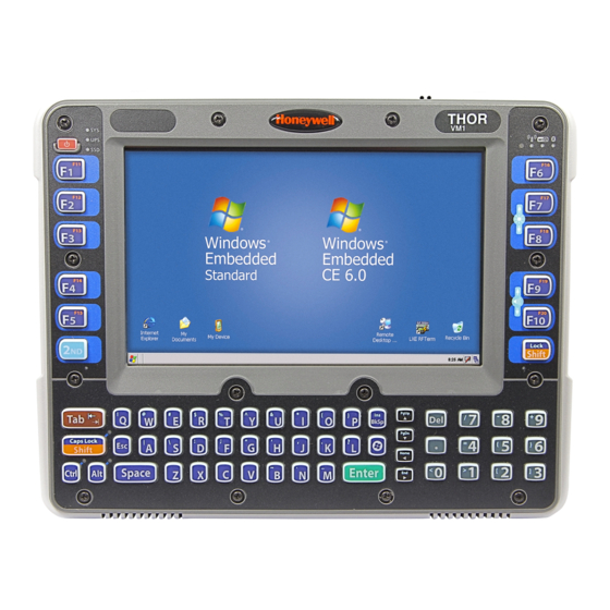
Components Front View 1. Power Button 2. Speakers 3. Microphone 4. Ambient Light Sensor... -
Page 13: Back View With Quick Mount Smart Dock
Back View with Quick Mount Smart Dock 1. Antenna Connectors (on Thor VM1) 2. SIM card Access Panel (on Thor VM1) 3. COM1 Connector (on Dock) 4. COM2 Connector (on Dock) 5. USB Connector (on Dock) 6. CAN/Audio Connector (on Dock) 7. -
Page 15: Chapter 2: Hardware
Chapter 2: Hardware System Hardware 802.11a/b/g/n Wireless Client The Thor VM1 has an 802.11a/b/g/n network card that supports diversity with two internal or external antennas. Power management for the network card is configured with the Summit Client Utility. Central Processing Unit The CPU is a 1.6 GHz Intel Atom processor. -
Page 16: Input/Output Components
When a headset is plugged into the adapter cable, the main speakers are disabled. A microphone is located at the upper right of the Thor VM1 display, near the Thor VM1 emblem. When a headset is plugged into the adapter cable, the internal microphone is disabled. -
Page 17: Bluetooth Lxez Pair
Bluetooth LXEZ Pair The Thor VM1 contains Bluetooth version 2.0 with Enhanced Data Rate (EDR) up to 3.0 Mbit/s over the air. Bluetooth device connection (or pairing) can occur at distances up to 32.8 ft (10 meters) Line of Sight. The wireless client retains wireless connectivity while Bluetooth is active. -
Page 18: Power
Vehicle DC Power Supply Vehicle power input for the Thor VM1 dock is 10V to 60V DC and is accepted without the need to perform any manual operation within the Thor VM1 dock. The dock provides a conditioned power output for the Thor VM1. By using a specified DC-to-DC adapter, input voltage of 72-144V DC nominal can be accepted. -
Page 19: Backup Battery
If operating on UPS power and the UPS battery becomes critically low, the Thor VM1 performs a controlled shutdown. If there is no external power available, there must be 10% or greater power in the UPS battery or the Thor VM1 does not power The UPS status LED and the Battery Control Panel can be used to monitor the state of the UPS battery. -
Page 20: Power Management Modes
Off Mode The Thor VM1 turns off if the user presses the power button when the Thor VM1 is On. The Thor VM1 is also off when it is not connected to a power source and the UPS battery is depleted. However, an internal Real Time Clock (RTC) powered by an... -
Page 21: Power Controls
The power switch has a raised bump to identify the switch position even when it is hidden from view. When the side of the switch with the raised bump is pressed, the power switch is On. If the Dock is connected to external power, the Dock delivers power to the Thor VM1. Thor VM1 Power Button... -
Page 22: Auto On Behavior
The Thor VM1 is turned on and off manually by the user using the power button on the front of the device. Ignition Control The Thor VM1 is turned on automatically when a signal is received via the Ignition Input wire, which is part of the DC Power Cable. -
Page 23: External Connectors
External Connectors Power the Thor VM1 off before attaching a cable to any port (serial, USB, Audio/CAN, etc.). Most external connectors for the Thor VM1 are located on the Quick Mount Smart Dock: COM1 connects to a serial bar code scanner, screen blanking cable, serial printer or PC. -
Page 24: Serial Connector (Com1 And Com2)
The COM1 and COM2 connectors are D-9 male connectors located on the back of the Quick Mount Smart Dock. Power the Thor VM1 off before attaching a cable to any port (serial, USB, Audio/CAN, etc.). The serial connectors are industry-standard RS-232, PC/AT standard 9–pin “D” male connector. -
Page 25: Screen Blanking
Screen Blanking The screen blanking signal can be provided either by a Honeywell Screen Blanking Box or a user supplied switch or relay. screen blanking box can be used on a vehicle that provides voltage on vehicle motion. Voltage must be within the range specified on the screen blanking box label. -
Page 26: Screen Blanking Box
The Screen Blanking Box is designed to monitor a connection to a vehicle motion sensing circuit. When motion is detected, the Screen Blanking Box opens the connection between the output feeds (which are connected to Pins 7 and 8 of the Thor VM1) and the display on the Thor VM1 is blanked. -
Page 27: Usb Connector
USB Connector The USB connector is a D-9 female connector located on the back of the Quick Mount Smart Dock. Power the Thor VM1 off before attaching a cable to any port (serial, USB, Audio/CAN, etc.). Signal Description Common ground... -
Page 28: Usb Dongle Cable
USB Dongle Cable USB dongle cables have a Host port and a Client port. The USB Client port is not used when the Thor VM1 has a Windows Embedded Standard operating system. 1. D9 Connector 2. USB Host Connector(s) 3. USB Client Connector... -
Page 29: Usb Host Connector
5V_USB USB Power, Current Limited USB_H1_D- USB D- USB_H1_D+ USB D+ USB Power Return Shell CGND Chassis Ground USB Client Connector The USB Client connector is not supported on the Thor VM1 with the Windows Embedded Standard operating system. 2-15... -
Page 30: Power Supply Connector
2. Power Switch Power is supplied to the Thor VM1 through the power connector. Additionally this assembly provides a connection point for the vehicle’s chassis ground to be connected internally to the conductive chassis of the computer. The Thor VM1 internal power supply can accept DC input voltages in the range of 10 to 60 Volts DC. -
Page 31: Canbus / Audio Connector
The CANbus/Audio connector is a D-15 male connector located on the back of the Quick Mount Smart Dock. The connector supports a headset adapter cable or a CANbus cable. The Thor VM1 does not support connecting audio and CANbus simultaneously. -
Page 32: Headset Adapter Cable
Headset Adapter Cable The headset cable attaches to the CANbus / Audio connector and provides a quick connect connection for a headset. D15 Female Connector Signal Description Not used Not used Not used Not used Not used Audio return Headset return Audio output Headset output Mic input... -
Page 33: Quick Connect Headset Connector
Quick Connect Headset Connector Signal Description Mic input Microphone input Mic return Microphone return Audio output Headset output Audio return Headset return 2-19... -
Page 34: Canbus Cable
CANbus Cable The CANbus interface is a virtual COM4 port. This port can be accessed using standard Windows API calls. D15 Female Connector Signal Description Not used CAN_L CAN_L bus line dominant low CAN_GND CAN ground CAN reserved Ground Not used Not used Not used Not used... -
Page 35: 9-Pin J1939 (Deutsch) Connectors
9-Pin J1939 (Deutsch) Connectors Receptacle Socket J1939 Female J1939 Male Signal Description CAN_GND CAN Ground CAN_V+ Option CAN external Power Supply CAN_H CAN_H bus line dominant high CAN_L CAN_L bus line dominant low CAN_SHLD Not used Not used Not used Not used 2-21... -
Page 36: Antenna Connections
Remove the rubber cap, if present, from the antenna connector before connecting an external antenna. Internal WiFi Antenna If the internal WiFi antenna option is ordered, an antenna is mounted inside the Thor VM1. The internal antenna is not user accessible. -
Page 37: Keyboard Options
64-Key QWERTY Keyboard The Thor VM1 has a QWERTY keyboard, available with a standard overlay, an IBM 3270 overlay or an IBM 5250 overlay. Because the keyboard only has 64 keys, all functions are not visible (or printed on the keyboard). Therefore the Thor VM1 keyboard supports what is called hidden keys -- keys that are accessible but not visible on the keyboard. -
Page 38: Ibm 3270 Overlay
IBM 3270 Overlay 2-24... -
Page 39: Ibm 5250 Overlay
IBM 5250 Overlay 2-25... -
Page 40: Keyboard Leds
Press either Shift key to toggle Shift On and Off. press 2nd plus either Shift key to toggle CapsLock On or Off. Secondary Keys LED The Thor VM1 keyboard is equipped with several secondary keys. These keys are identified by the superscript text found on the keyboard keys. -
Page 41: Led Functions
LED Functions System LEDs Connection LEDs 3. 2nd LED 4. Shift/CapsLock LED 5. Shift/CapsLock LED 6. Ctrl LED 7. Alt LED System LEDs 1. SYS (System Status) LED 2. UPS (Uninterruptible Power Supply) LED 3. SSD (Solid State Drive) LED 2-27... -
Page 42: Sys (System Status) Led
SYS (System Status) LED LED Behavior System State Solid Green On but Display Off Green blinking very slowly Hibernate, External power present Standby (1/2 sec. on, 4 1/2 sec. off) Hibernate, External power not present Standby Green blinking slowly CPU temperature less than -20ºC, External power present Heater warming CPU for 30 seconds (1/2 sec. -
Page 43: Ups Status Led
UPS Status LED The behavior of the UPS LED depends if external power is connected or not. External Power Present LED Behavior Status No UPS charging, UPS charged Solid Green UPS charging Any charging fault, Out of charging temperature range, Solid Amber No UPS present, Charge timeout... -
Page 44: Connection Leds
Connection LEDs 1. WWAN LED 2. WiFi LED 3. Bluetooth LED WWAN LED LED Behavior Status Solid Green Indicates a WWAN connection to a network. Indicates no WWAN connection. WiFi LED LED Behavior Status Solid Green Indicates a connection with an IP address to an Access Point Indicates no connection to an Access Point. -
Page 45: Keyboard Leds
Keyboard LEDs The keyboard LEDs are located near the specified key. 2nd LED LED Behavior Status Indicates the 2nd modifier key is active. 2nd mode is invoked for the next keypress only. Solid Green Pressing the 2nd key a second time exits this modifier mode and turns off the LED. 2nd mode is not invoked. -
Page 46: Alt Led
Alt LED LED Behavior Status Indicates the Alt modifier key is active. Alt mode is invoked for the next keypress only. Solid Green Pressing the Alt key a second time exits this modifier mode and turns off the LED. Alt mode is not invoked. 2-32... -
Page 47: Display
Display Backlight Control The display brightness on a Thor VM1 equipped with an outdoor display can be configured to automatically adjust depending on the ambient light level (Start > Settings > Control Panel >... -
Page 48: Disconnect Ups Battery
1. For convenience, the Thor VM1 can be removed from the Quick Mount Vehicle Dock, though it is not necessary. 2. If the Thor VM1 remains in the Dock, disconnect the power cable from the Dock. 3. Shutdown the Thor VM1. - Page 49 Thor VM1. 8. Reattach the access panel, torquing the M3 screws to 4-5 inch pounds using a #2 Philips bit. 9. When the Thor VM1 is attached to external power, the UPS battery is automatically reconnected. 2-35...
-
Page 50: Install Sd Card
4. Using a Phillips screwdriver (not supplied) loosen the screws and then remove the tethered access panel with the SSD and SD label. This panel is on the left hand side when the Thor VM1 is face down with the top away from the user. - Page 51 6. Slide the SD card into the slot. The label side (front) of the SD card faces toward the back of the Thor VM1. 7. Reattach the access panel, torquing the screws to 4-5 inch pounds. 8. If removed, reinstall the Thor VM1 in the Dock.
-
Page 52: Install Sim Card
4. Using a Phillips screwdriver (not supplied) loosen the screws and then remove the tethered access panel with the SIM label. This panel is on the right hand side when the Thor VM1 is face down with the top away from the user. - Page 53 6. Slide the SIM card into the slot. 7. Reattach the access panel, torquing the screws to 4-5 inch pounds. 8. If removed, reinstall the Thor VM1 in the Dock. 9. Restart the Thor VM1 2-39...
-
Page 54: Field Replaceable Front Panel
The front panel of the Thor VM1 is field replaceable. The front panel assembly contains the keyboard, touch screen and optional defroster. Should any of these components fail, the front panel assembly can easily be replaced to reduce downtime. - Page 55 6. Position the replacement front panel so the tab on the back of the front (D in figure above) panel lines up with the slot (A in figure above) on the Thor VM1. Be sure the two wiring connectors (B and C in figures above) are also aligned.
-
Page 56: Field Replaceable Ups Battery
Before replacing the Thor VM1 UPS battery, the internal UPS battery must be disconnected. The UPS battery in the Thor VM1 is field replaceable. Should the UPS battery fail, it can easily be replaced to minimize downtime. Replace UPS Battery 1. - Page 57 11. Place the UPS battery into the well. Note the orientation of the battery in the illustration below. The flat surface of the battery points toward the bottom of the Thor VM1. Make sure all wires are inside the battery well so they are not pinched when the front panel is reinstalled..
- Page 58 12. Position the front panel so the tab on the back of the front (D in figure above) panel lines up with the slot (A in figure above) on the Thor VM1. Be sure the two wiring connectors (B and C in figures above) are also aligned.
-
Page 59: Chapter 3: Software
After the system files are processed, Microsoft Windows begins to load. Windows maintains a System Registry and INI files. Standard Windows configuration options apply to the Thor VM1. Configuration options are located in the System Tray or the Control Panel: The System Tray contains icons for adjusting the time, date or volume level. -
Page 60: Drive C Folder Structure
Microsoft Windows device drivers, please refer to commercially available Windows OS reference guides. Radio Software The Thor VM1 is delivered with the radio software installed. Because the Thor VM1 uses a Microsoft Windows operating system, the radio installation includes Windows device drivers. -
Page 61: Programs Loaded On Drive C
Start > Control Panel > Wi-Fi Manage wireless clients installed in the Thor VM1. Freefloat Link*One Wedge (Optional) Link*One bar code decoder configuration software is available on the Thor VM1. Click here for the Freefloat website. Freefloat Access*One TE (Optional) Access*One terminal emulation software is available on the Thor VM1. -
Page 62: Control Panel
Control Panel Most control panel applets on the Thor VM1 are standard Microsoft Windows items. The control panels and other functions listed below may differ from a standard Microsoft Windows equipped PC or laptop. About Start > Control Panel > About (Classic view) The Software, Hardware and Versions tabs displays hardware and software version information as stored in the registry. -
Page 63: Autoon
Ignition Control The Thor VM1 is turned on automatically when a signal is received via the Ignition Input wire, which is part of the DC Power Cable. The power switch on the Quick Mount Smart Dock must be On. -
Page 64: Auto-On
Auto-On The Thor VM1 automatically powers up when power is provided. This could be from switched vehicle power, the power switch on the Quick Mount Smart Dock being placed in the On position or external AC power being applied. The power switch on the Quick Mount Smart Dock must be On for external power to control the device. -
Page 65: Bluetooth
Bluetooth Start > Control Panel > Bluetooth Note: Contact Technical Assistance for upgrade availability if your Bluetooth control panel is not the same as the control panel presented in this section. Discover and manage pairing with nearby Bluetooth devices. Factory Default Settings Discovered Devices None Settings... - Page 66 It is not necessary to disconnect a paired scanner and printer before a different scanner or printer is paired with the Thor VM1. The target Bluetooth device should be as close as possible (up to 32.8 ft (10 meters) Line of Sight) to the Thor VM1 during the pairing process.
-
Page 67: Bluetooth Devices
Bluetooth Devices The Bluetooth Devices tab displays any device previously discovered and paired with the Thor VM1. -
Page 68: Discover
When an active paired device enters Suspend Mode, is turned Off or leaves the Thor VM1 Bluetooth scanning range, the Bluetooth connection between the paired device and the Thor VM1 is lost. There may be audible or visual signals as paired devices disconnect from the Thor VM1. -
Page 69: Bluetooth Device List
The Bluetooth panel assigns an icon to the device name. An icon with a red background indicates the device's Bluetooth connection is inactive. An icon with a white background indicates the device is connected to the Thor VM1 and the device's Bluetooth connection is active. -
Page 70: Bluetooth Device Menu
Stop the connection between the Thor VM1 and the highlighted paired Bluetooth device. Remove an unpaired device from the Bluetooth device list. The highlighted device name and iden- Delete tifier is removed from the Thor VM1 Bluetooth Devices panel after the user taps OK. Properties More information on the highlighted Bluetooth device. -
Page 71: Settings
Settings Note: These options can still be checked or unchecked whether Bluetooth connection is enabled or disabled. Turn Off Bluetooth Tap the button to toggle the Bluetooth client On or Off. The button title changes from Turn Off Bluetooth to Turn On Bluetooth. Default The default value is Bluetooth On. -
Page 72: Options
Enable this option to ensure other devices can discover the Thor VM1. This option is Enabled by default. A dialog box appears on the Thor VM1 screen notifying the user a Bluetooth device requests to pair with the Thor VM1. -
Page 73: Reconnect
Reconnect Note: These options can still be checked or unchecked whether Bluetooth connection is enabled or disabled. 3-15... -
Page 74: Options
Options Option Function This option is Enabled (checked) by default. There may be an audio or visual signal when a connection between a paired, active device is Report when connection lost. lost A visual signal may be a dialog box placed on the display notifying the user the connection between one (or all) of the paired Bluetooth devices has stopped. - Page 75 Option Function This option is Enabled (checked) by default. This option controls the overall mobile Bluetooth device reconnect behavior. When Auto Reconnect is disabled (unchecked), Auto Reconnect on Boot is automatically disabled and dimmed. When Auto Reconnect is disabled (unchecked), no devices are reconnected in any situation.
-
Page 76: About
About This panel lists the assigned Computer Friendly Name (that other devices may discover during their Discovery and Query process), the Bluetooth MAC address, and software version levels. The data cannot be edited by the user. 3-18... -
Page 77: Using Bluetooth
Computer Friendly Name at the bottom of the Settings display. The Bluetooth Thor VM1 default name is the Computer Description. Honeywell strongly urges assigning every Thor VM1 a unique name (up to 32 characters) before Bluetooth Discovery is initiated. 4. Check or uncheck the Thor VM1 Bluetooth options on the Settings tab. -
Page 78: Subsequent Use
LED on the device, or a dialog box is placed on the Thor VM1 display. 10. Whenever the Thor VM1 is turned On, all previously paired, live, Bluetooth devices in the vicinity are paired, one at a time, with the Thor VM1. -
Page 79: Bluetooth Indicators
Note: When an active paired device enters Suspend Mode, is turned Off or leaves the Thor VM1 Bluetooth scan range, the Bluetooth connection between the paired device and the Thor VM1 is lost. There may be audible or visual signals as paired devices disconnect from the Thor VM1. -
Page 80: Bluetooth Bar Code Reader Setup
To open the LXEZ Pair program, tap Start > Control Panel > Bluetooth or tap the Bluetooth icon on the desktop or tap the Bluetooth icon in the taskbar. Locate the bar code label, similar to the one shown above, attached to the Thor VM1. The label is the Bluetooth address identifier for the Thor VM1. -
Page 81: Thor Vm1 Without Label
Thor VM1 without Label If the Thor VM1 Bluetooth address bar code label does not exist, follow these steps to create a unique Bluetooth address bar code for the Thor VM1: First, locate the Thor VM1 Bluetooth address by tapping Start > Control Panel > Bluetooth > About tab. -
Page 82: Bluetooth Beep And Led Indications
Assistance for assistance. Bluetooth Printer Setup The Bluetooth managed device should be as close as possible, in direct line of sight, with the Thor VM1 during the pairing process. 1. Open the LXEZ Pair Panel. 2. Tap Discover. Locate the Bluetooth printer in the Discovery panel. -
Page 83: Display
Display Start > Control Panel > Display (Classic View) Start > Control Panel > Appearance and Themes (Category View) The Thor VM1 supports 800 x 480 pixel display resolution. Screen rotation and other configuration options including Screen Blanking, Screen Defroster Control and Automatic Display Brightness (outdoor display only) are configured on separate control panels. -
Page 84: Power Options
Start > Control Panel > Performance and Maintenance> Power Options (Category View) Power Schemes Power schemes can be configured that will be in effect when the Thor VM1 is attached to an external power supply or the UPS battery. 3-26... -
Page 85: Power Meter
Power Meter On the Power Meter tab, battery #1 refers to the UPS battery. Shows power status: external power or UPS battery and the total battery power remaining before a recharge is necessary. 3-27... -
Page 86: Advanced
The Advanced panel allows setting the power button behavior when the unit is on and the power button is pressed. Options are: Do nothing Ask me what to do Stand by Shut down. The default is to shut down. The Thor VM1 performs an orderly shut down when the power key is pressed when this option is enabled. 3-28... -
Page 87: Hibernate
Hibernate By default, hibernate is disabled on the Thor VM1. The default can be changed on this page. The disk space necessary for hibernation plus the free disk space on the hard drive are listed. 3-29... -
Page 88: Screen Control
If Automatic Brightness Control is enabled for an outdoor display, the value for LCD Brightness depends on the Ambient Light %. Note: There is no default value for Ambient Light % as it varies depending on the level of light where the Thor VM1 is located. 3-30... -
Page 89: Screen Blanking
Screen blanking allows the Thor VM1 display to automatically be turned off whenever the vehicle is in motion. Use the Screen on delay to specify the period of time in ms (milliseconds) between when the vehicle stops and the Thor VM1 screen turns on. -
Page 90: Automatic Brightness Control
When the ambient light exceeds the threshold specified in Medium to high light level (%), the display backlight is automatically increased to a high level. Likewise if the Thor VM1 is returned to a lower ambient light area, the display backlight automatically transitions to the appropriate lower display backlight level. -
Page 91: Screen Rotation
Screen Rotation Start > Control Panel > Screen Rotation (Classic view) The Screen Rotation panel provides options for rotating the display: 0 Degree - Returns screen to the default orientation. 90 Degree - Rotates the screen counter clockwise 90 degrees as compared to the default orientation. 180 Degree - Rotates the screen 180 degrees as compared to the default orientation. -
Page 92: Sounds
Sounds Start > Control Panel > Sounds and Audio Devices (Classic View) Start > Control Panel > Sounds, Speech and Audio Devices (Category View) Use the slider bar to adjust the volume level as desired. Alternatively: Tap the Volume icon, if present, in the taskbar and move the slider until the volume level is as desired. Use function keys - press the 2nd key then F9 to adjust volume up or 2nd then F10 to adjust volume down. -
Page 93: User Accounts
User Accounts Note: The following applies to a Thor VM1 that is not part of a domain. When the Thor VM1 is part of a domain, the user is prompted for credentials at Windows startup or log on. The Thor VM1 is pre-configured with an administrator account named Administrator. By default, the Thor VM1 automatically logs onto the Administrator account at Windows startup. -
Page 94: Bar Code Readers
Scanner. The BTRS module is configured by scanning the bar codes in the Bluetooth Ring Scanner Guide. Scanner Wedge Honeywell provides Freefloat Link*One for bar code decoding needs on the Thor VM1 when equipped with a Windows Embedded Standard operating system. Click... -
Page 95: Touch Screen Calibration
Touch Screen Calibration Start > Programs > PenMount Windows Universal Driver To calibrate the touch screen, tap Start > Programs > PenMount Universal Driver > Utility > PenMount Control Panel. Select PenMount 6000 USB and then tap Configure. Select Standard Calibration or Advance Calibration. Advanced Calibration allows the user to select the number of calibration points. -
Page 96: Bios
The second device is the Windows CE Image. If a USB drive, such as a thumb drive is attached to the Thor VM1, the device attempts to boot from the USB drive: If the USB drive contains a bootable sector, the Thor VM1 boots from the USB drive. -
Page 97: The Thor Vm1 Recovery Dvd
The Thor VM1 Recovery DVD A recovery DVD is available to restore the software on your Thor VM1 to the same state it had when it was shipped from the factory. Contact Technical Assistance for information on the recovery DVD. - Page 98 3-40...
-
Page 99: Chapter 4: Wireless Network Connections
EAP-FAST Important Notes It is important that all dates are correct on the Thor VM1 and host computers when using any type of certificate. Certificates are date sensitive and if the date is not correct authentication will fail. It may be necessary to upgrade radio software in order to use certain Summit Client Utility (SCU) features. -
Page 100: Summit Client Utility
Summit Tray Icon Tray icon is not shown when the Thor VM1 is running Windows Embedded Standard. The Windows Wireless icon (located in the taskbar) may not display a successful wireless connection. The SCU Main tab... -
Page 101: Wireless Zero Config Utility
2. A message appears that a Power Cycle is required to make settings activate properly. 3. Tap OK. 4. Restart the Thor VM1. The Summit Client Utility passes control to Wireless Zero Config and the WZC Wireless Information control panel. Using the options in the Wireless Zero Config panels, set up radio and security settings. -
Page 102: Main Tab
Main Tab Start > All Programs > Summit > Summit Client Utility > Main tab Factory Default Settings Admin Login SUMMIT Radio Enabled Active Config/Profile Default Regulatory Domain FCC, ETSI or Worldwide The Main tab displays information about the wireless client device including: SCU (Summit Client Utility) version Driver version Radio Type (ABGN is an 802.11 a/b/g/n radio). -
Page 103: Admin Login
The Disable Radio button can be used to disable the network card. Once disabled, the button label changes to Enable Radio. By default the radio is enabled. The Admin Login button provides access to editing wireless parameters. Profile and Global may only be edited after entering the Admin Login password. -
Page 104: Profile Tab
Profile Tab Start > All Programs > Summit > Summit Client Utility > Profile tab Note: Tap the Commit button to save changes before leaving this panel or the SCU. If the panel is exited before tapping the Commit button, changes are not saved! Factory Default Settings Profile Default... -
Page 105: Buttons
Buttons Button Function Commit Saves the profile settings made on this screen. Settings are saved in the profile. Allows entry of a username and password, certificate names, and other information required to authenticate with Credentials the access point. The information required depends on the EAP type. Deletes the profile. -
Page 106: Profile Parameters
Options are: None, WEP (or Manual WEP), WEP EAP (or Auto WEP), WPA PSK, WPA TKIP, WPA CCKM, WPA2 PSK, WPA2 AES, or WPA2 CCKM. Encryption None CKIP is not supported in the Thor VM1. Note: The Encryption type chosen determines if the WEP Keys / PSK Keys button is active and also determines the available entries in the WEP or PSK pop-up window. - Page 107 It is important the Radio Mode parameter correspond to the AP to which the device is to connect. For example, if this parameter is set to G rates only, the Thor VM1 may only connect to APs set for G rates and not those set for B and G rates.
-
Page 108: Status Tab
Status Tab Start > All Programs > Summit > Summit Client Utility > Status tab This screen provides information on the radio: The profile being used. The status of the radio card (down, associated, authenticated, etc.). Client information including device name, IP address and MAC address. Information about the Access Point (AP) maintaining the connection to the network including AP name, IP address and MAC address. -
Page 109: Diags Tab
Diags Tab Start > All Programs > Summit > Summit Client Utility > Diags tab The Diags screen can be used for troubleshooting network traffic and radio connectivity issues. (Re)connect – Use this button to apply (or reapply) the current profile and attempt to associate or authenticate to the wireless LAN. -
Page 110: Global Tab
Global Tab Start > All Programs > Summit > Summit Client Utility > Global tab The parameters on this panel can only be changed when an Admin is logged in with a password. The current values for the parameters can be viewed by the general user without requiring a password. Note: Tap the Commit button to save changes. -
Page 111: Custom Parameter Option
Logon Options Use SCU credentials Custom Parameter Option The parameter value is displayed as “Custom” when the operating system registry has been edited to set the Summit parameter to a value that is not available from the parameter’s drop down list. Selecting Custom from the drop down list has no effect. -
Page 112: Global Parameters
Global Parameters Parameter Default Function If signal strength is less than this trigger value, the client looks for a different Access Point with a stronger signal. Roam Trigger -65 dBm Options are: -50 dBm, -55, -60, -65, -70, -75, -80, -85, -90 dBm or Custom. The amount by which a different Access Point signal strength must exceed the current Access Point signal strength before roaming to the different Roam Delta... - Page 113 Parameter Default Function Options are: On, Off Use of Cisco Compatible Extensions (CCX) radio management and AP specified maximum transmit power features. Options are: Full - Use Cisco IE and CCX version number, support all CCX features. The option known as "On" in previous versions. CCX or CCX Features Optimized Optimized –Use Cisco IE and CCX version number, support all CCX...
- Page 114 Determines if the Summit icon is displayed in the System tray. Options are: On, Off Tray Icon The tray icon is not displayed when the Thor VM1 is running a Windows Embedded Standard operating system. When On, the Summit Config Utility masks passwords (characters on the screen are displayed as an *) as they are typed and when they are viewed.
-
Page 115: Logon Options
Parameter Default Function A valid directory path, of up to 64 characters, where WPA Certificate Authority and User Certificates are stored on the mobile device when not using the Windows certificates store. Ensure the Windows folder path exists before assigning the path in this parameter. See Certificates for instructions Certs Path... -
Page 116: Single Signon
Click the Logon Options button. Single Signon To use the Single Signon option, select the checkbox for Use the Windows username and password when available. When the active profile is using LEAP, PEAP-MSCHAP, PEAP-GTC or EAP-FAST, the SCU ignores the username and password, if any, saved in the profile. - Page 117 EAP authentication is required for a WLAN connection Single Signon is configured, so the Windows username and password are used as credentials for EAP authentication The WLAN connection needs to be established before the Windows login. Once this option is enabled, the Authentication delay and Association timeout values can be adjusted as necessary. Both values are specified in milliseconds (ms).
-
Page 118: Sign-On Vs. Stored Credentials
The Username and Password are left blank on the Credentials screen. When the device attempts to connect to the network, a sign on screen is displayed. The user must enter the Username and Password at that time to authenticate. When using Summit with the Thor VM1, there is an option on the Global tab to use the Windows user name and password to log on instead of any username and password stored in the profile. -
Page 119: How To: Use Windows Username And Password
5. The default is to use the entire certificate store for the CA certificate. Alternatively, use the Browse button next to the CA Cert (CA Certificate Filename) on the Credentials screen to select an individual certificate. 6. For EAP-TLS, also enter the User Cert (User Certificate filename) on the credentials screen by using the Browse button. -
Page 120: Windows Certificate Store Vs. Certs Path
Windows Certificate Store vs. Certs Path Note: It is important that all dates are correct on the Thor VM1 and host computers when using any type of certificate. Certificates are date sensitive and if the date is not correct authentication will fail. - Page 121 6. Uncheck the Use full trusted store checkbox. 7. Select the desired certificate and click the Select button to return the selected certificate to the CA Cert textbox. 8. Click OK to exit the Credentials screen and then Commit to save the profile changes. 4-23...
-
Page 122: Configuring The Profile
Configuring the Profile Use the instructions in this section to complete the entries on the Profile tab according to the type of wireless security used by your network. The instructions that follow are the minimum required to successfully connect to a network. Your system may require more parameters than are listed in these instructions. -
Page 123: No Security
No Security To connect to a wireless network with no security, make sure the following profile options are used. Enter the SSID of the Access Point assigned to this profile Set EAP Type to None Set Encryption to None Set Auth Type to Open Once configured, click the Commit button. -
Page 124: Wep
To connect using WEP, make sure the following profile options are used. Enter the SSID of the Access Point assigned to this profile Set EAP Type to None Set Encryption to WEP or Manual WEP (depending on SCU version) Set Auth Type to Open Click the WEP keys/PSKs button. - Page 125 Ensure the correct Active Profile is selected on the Main tab and restart. The SCU Main tab shows the device is associated after the radio connects to the network. 4-27...
-
Page 126: Leap
LEAP To use LEAP (without WPA), make sure the following profile options are used. Enter the SSID of the Access Point assigned to this profile Set EAP Type to LEAP Set Encryption to WEP EAP or Auto WEP (depending on SCU version) Set Auth Type as follows: If the Cisco/CCX certified AP is configured for open authentication, set the Auth Type radio parameter to Open. - Page 127 Enter the Domain\Username (if the Domain is required), otherwise enter the Username. Enter the password. Click OK then click Commit. Ensure the correct Active Profile is selected on the Main tab and restart. The SCU Main tab shows the device is associated after the radio connects to the network.
-
Page 128: Peap/Mschap
PEAP/MSCHAP To use PEAP/MSCHAP, make sure the following profile options are used. Enter the SSID of the Access Point assigned to this profile Set EAP Type to PEAP-MSCHAP Set Encryption to WPA TKIP Set Auth Type to Open To use another encryption type, select WPA CCKM, WPA2 AES or WPA2 CCKM for encryption and complete other entries as detailed in this section. - Page 129 Enter the Domain\Username (if the Domain is required), otherwise enter the Username. Enter the password. Leave the CA Certificate File Name blank for now. Click OK then click Commit. Ensure the correct Active profile is selected on the Main Tab. Windows Certificate Store vs.
-
Page 130: Peap/Gtc
PEAP/GTC To use PEAP/GTC, make sure the following profile options are used. Enter the SSID of the Access Point assigned to this profile Set EAP Type to PEAP-GTC Set Encryption to WPA TKIP Set Auth Type to Open To use another encryption type, select WPA CCKM, WPA2 AES or WPA2 CCKM for encryption and complete other entries as detailed in this section. - Page 131 Enter the Domain\Username (if the Domain is required), otherwise enter the Username. Enter the password. Leave the CA Certificate File Name blank for now. Click OK then click Commit. Ensure the correct Active Profile is selected on the Main Tab. Windows Certificate Store vs.
-
Page 132: Wpa/Leap
WPA/LEAP To use WPA/LEAP, make sure the following profile options are used. Enter the SSID of the Access Point assigned to this profile Set EAP Type to LEAP Set Encryption to WPA TKIP Set Auth Type as follows: If the Cisco/CCX certified AP is configured for open authentication, set the Auth Type radio parameter to Open. - Page 133 Enter the Domain\Username (if the Domain is required), otherwise enter the Username. Enter the password. Click OK then click the Commit button. Ensure the correct Active Profile is selected on the Main tab and restart. The SCU Main tab shows the device is associated after the radio connects to the network.
-
Page 134: Eap-Fast
RADIUS server must have auto provisioning enabled to send the PAC provisioning credentials to the Thor VM1. For automatic PAC provisioning, once a username/password is authenticated, the PAC information is stored on the Thor VM1. The same username/password must be used to authenticate each time. See the note below for more details. - Page 135 To use Sign-On credentials: Do not enter a User and Password as the user will be prompted for the Username and Password when connecting to the network. To use Stored Credentials: Enter the Domain\Username (if the Domain is required), otherwise enter the Username. Enter the password.
-
Page 136: Eap-Tls
EAP-TLS To use EAP-TLS, make sure the following profile options are used. Enter the SSID of the Access Point assigned to this profile Set EAP Type to EAP-TLS Set Encryption to WPA TKIP Set Auth Type to Open To use another encryption type, select WPA CCKM, WPA2 AES or WPA2 CCKM for encryption and complete other entries as detailed in this section. - Page 137 If using the Certs Path option: Leave the Use MS store box unchecked. Enter the certificate filename in the CA Cert textbox. Click OK then click Commit. The Thor VM1 should be authenticating the server certificate and using EAP-TLS for the user authentication. 4-39...
- Page 138 Ensure the correct Active Profile is selected on the Main tab and restart. The SCU Main tab shows the device is associated after the radio connects to the network. Certificates for information on generating a Root CA certificate or a User certificate. Note: The date must be properly set on the device to authenticate a certificate.
-
Page 139: Wpa Psk
WPA PSK To connect using WPA/PSK, make sure the following profile options are used: Enter the SSID of the Access Point assigned to this profile Set EAP Type to None Set Encryption to WPA PSK or WPA2 PSK Set Auth Type to Open Click the WEP keys/PSKs button. -
Page 140: Certificates
Please refer to the Security Primer to prepare the Authentication Server and Access Point for communication. Note: It is important that all dates are correct on the Thor VM1 and host computers when using any type of certificate. Certificates are date sensitive and if the date is not correct authentication will fail. -
Page 141: Generating A Root Ca Certificate
Certificates are date sensitive and if the date is not correct authentication will fail. The easiest way to get the root CA certificate is to use a browser on a PC or the Thor VM1 to navigate to the Certificate Authority. - Page 142 Click the Download a CA certificate, certificate chain or CRL link. Make sure the correct root CA certificate is selected in the list box. 4-44...
- Page 143 To download the CA certificate, click on the Download CA certificate link. Click the Save button and save the certificate. Make sure to keep track of the name and location of the certificate. Install the certificate on the Thor VM1. 4-45...
-
Page 144: Installing A Root Ca Certificate
C:\Program Files\Summit\certs folder or other path specified in the Summit Certs global parameter. Copy the certificate file to the Thor VM1. The certificate file has a .CER extension. Locate the file and double-tap on it. If presented with a security warning, confirm that you want to open the file. - Page 145 An import successful message is displayed. 4-47...
-
Page 146: Generating A User Certificate
Generating a User Certificate The easiest way to get the user certificate is to use the browser on the Thor VM1 or a PC to navigate to the Certificate Authority. To request the user certificate, open a browser to http://<CA IP address>/certsrv. - Page 147 Click the Request a certificate link. Click on the User Certificate link. 4-49...
-
Page 148: Exporting A User Certificate
The User Certificate is issued. Install the user certificate on the requesting computer by clicking the Install this certificate link. If the requesting computer is the Thor VM1, then the process is finished. otherwise, export the certificate as described below. Exporting a User Certificate Select Tools >... - Page 149 Make sure the Personal tab is selected. Highlight the certificate and click the Export button. The Certificate Export Wizard is started Select Yes, export the private key and click Next. Uncheck Enable strong protection and check Next. The certificate type must be PKCS #12 (.PFX). 4-51...
- Page 150 The certificate is saved with a .PFX extension. Click Finish. and OK to close the Successful Export message. Locate the User Certificate in the specified location. Copy to the Thor VM1. Install the User certificate. 4-52...
-
Page 151: Installing A User Certificate
3. The Certificate Import Wizard starts. 4. Tap Next and use the Browse... button to locate the User certificate copied to the Thor VM1. If necessary, change the file type drop down list at the bottom of the explorer window from *.cer to *.pfx. After selecting the .PFX file, tap Open. - Page 152 On the next screen, allow Windows to automatically select the certificate store, then click Next and Finish. An import successful message is displayed. 4-54...
-
Page 153: Oneclick Internet
If this delay is acceptable to the user, standby may be enabled. When the One Click Internet utility is displayed on screen and the Thor VM1 enters standby, the touch screen may remain inactive for 10-15 seconds after the Thor VM1 resumes from standby. - Page 154 You need the IMEI number for the Thor VM1 when you contact Verizon prior to activating service on the Thor VM1. The IMEI number can be found on the Settings > Info tab. The activation screen is displayed automatically after the Verizon firmware is selected. If the activation screen is not automatically displayed, double-tap the OneClick Internet icon on the desktop.
- Page 155 To verify your settings, tap on the OneClick Internet icon in the system tray. Tap Settings. Tap the Network tab. This screen contains the settings including the telephone number from the provider, in this case Verizon. 4-57...
-
Page 156: Using Oneclick Internet
Using OneClick Internet If OneClick Internet is not loaded, double-tap the desktop icon to load it. If OneClick Internet is loaded but minimized to the system tray, tap the OneClick Internet icon in the system tray to maximize it. How To: Connection Management 1. -
Page 157: Menu Buttons
Update Button One Click Internet provides a built-in online update functionality that allows for an automatic update of OneClick Internet application, device drivers, and APN database. Honeywell DOES NOT recommend using this option. Contact Technical Assistance for information on upgrading to another version of OneClick Internet. -
Page 158: Settings Button
Settings Button Access the Settings menu by tapping the Settings button on the main window. The following tabs are available: Profile Network History Info Firmware General 4-60... -
Page 159: Profile Tab
Profile Tab Create a connection profile to store connection information. Once a profile has been created, its name appears in the drop down Profiles list, which replaces the Profile Name textbox in the illustration above. 4-61... -
Page 160: Buttons
Buttons Button Description Create a new profile. When this option is selected, the Profile Name is a text box. Enter a name for the profile as well as other connection specific configuration. When finished, tap the Save button to save the new profile. -
Page 161: Network Tab
Network Tab The appearance of the network tab depends on the type of firmware selected. Network with SIM Card Select Connection Label Description Select automatically Selects the best suited network automatically Use GPRS/EDGE only Use only GPRS/EDGE for a connection Use UMTS/HSPA only Use only UMTS/HSPA for a connection. - Page 162 Select Network Use this option to select from available networks. Note: When you are registered to a CDMA network, you cannot select the network. "All CDMA network" is shown instead. Note: The network list only appears if the connection setting is Only use GPRS or Only use UMTS/HSPA. Select the network and tap on the register button.
-
Page 163: Cdma Network
CDMA Network Information on the CDMA network is displayed. There are no editable parameters on this screen. 4-65... -
Page 164: History Tab
History Tab The history shows the data volume transferred in a specified time frame. Select the From and To dates to see the data volume sent/received in the specified period. Tap Reset to reset the counter. PIN Tab You can Activate/Deactivate the PIN or Change the PIN. Activate/Deactivate PIN This tab is only displayed when a firmware is loaded that requires a SIM card (such as AT&T or T-Mobile). -
Page 165: Change Pin
Change PIN This dialog lets you change your PIN. Label Description Current PIN Enter the current PIN. New PIN Enter the new PIN. Verify PIN Verify the new PIN by entering it again. 4-67... -
Page 166: Info Tab
Info Tab This tab displays SIM card, modem and system Information. 4-68... -
Page 167: Firmware Tab
Firmware Tab OneClick Internet selects the correct Firmware matching your operator automatically, if a special firmware for your operator is available and a SIM card is inserted. If no specific firmware for your operator is available, generic firmware is selected. After a firmware has been selected, it appears as the Current Profile. -
Page 168: Activation On Cdma
Activation on CDMA When CDMA Firmware is selected, the activation of the modem on the CDMA network starts automatically. During the process of loading CDMA firmware, an activation window pop up allowing a choice between Manual Activation and Automated Activation. Label Description Manual Activation... -
Page 169: General Tab
General Tab Label Description When selected OneClick Internet launches automatically when the user starts the Thor VM1 and logs Auto Launch Connect Auto- When selected OneClick Internet automatically connects on start-up. matically Reconnect Auto- When selected OneClick Internet reconnects automatically when the Thor VM1 returns from standby matically or hibernate. -
Page 170: Application Tab
Application Tab Use the Application tab to specify any application to launch automatically once the Internet connection is established. Use the Browse button to locate the desired application. 4-72... -
Page 171: Application Buttons
Application Buttons The SMS Center window is split into menu bar, folder view, folder content and preview window. To manage your short messages you may: Button Description Manage SMS folders Change SMS settings Create new SMS/MMS messages Reply to SMS Forward SMS 4-73... -
Page 172: Folder
Button Description Move SMS to a folder Delete SMS Send and receive SMS/MMS (if supported) Manage phone book contacts on SIM and in Email client. Folder By using this menu, you may change the folder structure of the SMS Center: Button Description New Folder... -
Page 173: Reply
many parts the SMS consists of (one part has max. 160 characters/unicode70), the second number counts down from 160/70 characters. The number in parenthesis () counts the total number of characters. The recipient for your SMS has to be entered in the "To"... -
Page 174: Web Browser
Web Browser Clicking this button opens the Web Browser and allows the user to surf the Internet once the connection is established. The default browser is used, which is Internet Explorer by default on the Thor VM1. Email Clicking this button opens the Email application after the connection is established. The Email application is the default Email client set in the Control Panel (Start > Control Panel >... - Page 175 After Latitude and Longitude Data are displayed, the user can tap Track Me to open Google Maps, showing their current location on a map. Lat - Latitude - The location north or south of the equator in degrees. Lon - Longitude: The angular distance from the Prime Meridian in degrees. After Latitude and Longitude Data are displayed, the user can tap Clipboard and the latitude and longitude are copied to the clipboard cache.
-
Page 176: About
This does not mean that the Thor VM1 has been localized for these languages. Installing or Upgrading OneClick Internet Note: You must use the Honeywell supplied version of OneClick Internet. Do not change versions unless instructed by your Honeywell representative. One Click Internet is pre-installed before the Thor VM1 is shipped. -
Page 177: Installation
Installation When you double-click the Installer file for OneClick Internet, it extracts the files to install. Next, select the application language. By default, the language of the OS is used (if available). Review and accept the license agreement. Click Accept, if you agree. Otherwise please click Reject to cancel installation. 4-79... - Page 178 Next the installer asks for the installation directory. Use the Browse button to specify a location other than the default. Installation process is indicated on screen. When completed. click the Finish button to exit the installer. 4-80...
- Page 179 Start OneClick Internet from the Windows Program Menu or double-tap the desktop icon. 4-81...
-
Page 180: Oneclick Internet Connection Manager
OneClick Internet Connection Manager Launch OneClick Internet from the desktop icon or Windows Start Menu. When OneClick Internet is active, a status icon appears in the system tray. The main screen for OneClick Internet opens when the application is started. This screen displays basic information on the connection as well as access to more advanced features and details. -
Page 181: Information Buttons
Icon Description The SMS button is enabled if no Internet connection is active. When this button is active, tapping it accesses the integrated SMS application. Tap this button to launch the default browser. Email Tap this button to launch the default Email application. Tap this button access the integrated GPS tool. - Page 182 4-84...
-
Page 183: Chapter 5: Key Maps
Start > Control Panel > Power. Note: When automatic brightness control is enabled for a Thor VM1 with an Outdoor display, the manual display brightness controls in the table below have no effect. To get this Key / Function Press These Keys in this Order... - Page 184 Display Backlight Brightness Up F7 (see note above) Display Backlight Brightness Down 2nd F8 (see note above) Shift Shift Ctrl Ctrl Space Space CapsLock Shift Enter Enter Delete . (VK_DECIMAL) Back Space BkSp Insert BkSp Back Tab 2nd Tab Ctrl-Break Pause Up Arrow Up Arrow...
- Page 185 Shift Shift Shift Shift Shift Shift Shift Shift Shift Shift Shift Shift Shift Shift Shift...
- Page 186 Shift Shift Shift Shift Shift Shift Shift Shift Shift Shift Shift " . (VK_PERIOD) &...
- Page 187 > < Shift Shift Shift Shift Shift Shift & Shift Shift Shift Shift...
-
Page 188: Ibm Terminal Emulation
The Thor VM1IBM 3270 and IBM 5250 Terminal Emulator keypads are designed to allow the user to enter terminal emulator commands when running the RFTerm program. When running RFTerm on the Thor VM1, please refer to the RFTerm Reference Guide for equivalent keys and keypress sequences. -
Page 189: Ibm 5250
IBM 5250 Legend on Keypad Explanation Key Sequence Attn Attention Ctrl + A Clear Ctrl + C Delete Ctrl + D Duplicate Ctrl + U E-Inp Erase Input Ctrl + Bksp Field Exit Enter Enter Fld - Field Minus Ctrl + M Fld + Field Plus Ctrl + L... -
Page 191: Chapter 6: Technical Specifications
Chapter 6: Technical Specifications Thor VM1 Processor Atom CPU operating at 1.6 GHz. Memory 2GB SDRAM Mass Storage 4 or 8GB CompactFlash Storage Expansion User installable, supports 1 to 4GB SD card Operating System Microsoft Windows Embedded Standard 2009 802.11 a/b/g/n radio / Bluetooth... -
Page 192: Quick Mount Smart Dock
External power supply. AC Adapter. 120-240VAC to 12VDC DC Input Voltage: 10- 60 VDC Input Power Input Current: 4.6 Amps Input Fuse: 10A Time Delay Dimensions Thor VM1 Width 10.6” (26.8 cm) Height 8.4” (21.4 cm) Depth 1.7” (4.3 cm) to 2.6" (6.6 cm) (at latch) Weight 5.6 lb. -
Page 193: Environmental Specifications
Environmental Specifications Thor VM1 and Quick Mount Smart Dock Standard: -4°F to 122°F (-20°C to 50°C) [non-condensing] Operating Temperature Extended temperature: -22º to 122º F (-30ºC to 50ºC) [condensing] Storage Temperature Standard and Extended temperature: -22°F to 140°F (-30°C to 60°C) [non-condensing] 8 KV air, 4kV direct contact Standard: Up to 90% non-condensing at 104°F (40°C) -
Page 194: Network Card Specifications
50 mW max. FCC: 1-11, 36, 40 ,44, 48, 149, 153, 157, 161 Channels ETSI: 1-13, 36, 40, 44 ,48 Operating Temperature Same as Thor VM1 Operating Temperature Storage Temperature Same as Thor VM1 Storage Temperature Connectivity TCP/IP, Ethernet, ODI... -
Page 195: Chapter 7: Technical Assistance
Limited Warranty Honeywell International Inc. ("HII") warrants its products to be free from defects in materials and workmanship and to conform to HII’s published specifications applicable to the products purchased at the time of shipment. This warranty does not cover any HII product which is (i) improperly installed or used;... - Page 196 The duration of the limited warranty for the Thor VM1 is 1 year. The duration of the limited warranty for the Thor VM1 Quick Mount Smart Dock is 1 year. The duration of the limited warranty for the Thor VM1 Vehicle Mount Assembly is 1 year.
- Page 198 Honeywell Scanning & Mobility 9680 Old Bailes Road Fort Mill, SC 29707 www.honeywellaidc.com E-EQ-VM1WESRG Rev C 10/12...
Need help?
Do you have a question about the THOR VM1 and is the answer not in the manual?
Questions and answers