
Related Manuals for Honeywell Thor VM1 W


Summary of Contents for Honeywell Thor VM1 W
- Page 1 Thor™ VM1 W Vehicle-Mount Computer Microsoft® Windows® Embedded Standard Operating System User's Guide...
- Page 2 Disclaimer Honeywell International Inc. (“HII”) reserves the right to make changes in specifications and other information contained in this document without prior notice, and the reader should in all cases consult HII to determine whether any such changes have been made. The information in this publication does not represent a commitment on the part of HII.
-
Page 3: Table Of Contents
Microsoft Windows License Agreement (First Boot) Components Front View Back View Quick Mount Smart Dock Access Panels Chapter 2: Set Up A New Thor VM1 W Hardware Setup Software Setup Quick Mount Smart Dock Preparing the Dock Place the Thor VM1 W in the Dock... - Page 4 Adjust Headset / Microphone and Secure Cable 2-16 Cleaning the Touchscreen 2-17 Startup Help 2-18 Chapter 3: Connecting Cables to the Thor VM1 W Connect Cable - USB Host Connect Cable - Serial Connecting an AC/DC Power Supply Connecting a Tethered Scanner Connecting the Headset Cable...
-
Page 5: Chapter 1: Introduction
The Thor VM1 W contains a UPS battery which, when fully charged, can power the Thor VM1 W for a minimum of 30 minutes. This can be when the Thor VM1 W is not attached to a Quick Mount Smart Dock or when the Thor VM1 W is attached to a dock but the vehicle power is interrupted, such as when the vehicle battery is being changed. -
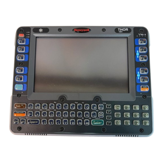
Page 6: Components
Components Front View 1. Power Button 2. Speakers 3. Ambient Light Sensor 4. Microphone... -
Page 7: Back View Quick Mount Smart Dock
Back View Quick Mount Smart Dock 1. Antenna Connectors (on Thor VM1 W) 2. SIM card Access Panel (on Thor VM1 W) 3. COM1 Connector (on Dock) 4. COM2 Connector (on Dock) 5. USB Connector (on Dock) 6. CAN/Audio Connector (on Dock) 7. -
Page 9: Chapter 2: Set Up A New Thor Vm1 W
Chapter 2: Set Up A New Thor VM1 W This page lists a quick outline of the steps you might take when setting up a new Thor VM1 W. More instruction for each step is listed later in this guide. Please refer to the Thor VM1 W Reference Guide for additional information and instruction. -
Page 10: Quick Mount Smart Dock
The Thor VM1 W assembly consists of two parts, the Thor VM1 W computer and the Quick Mount Smart Dock. The Thor VM1 W contains an internal UPS battery that, once fully charged, powers the Thor VM1 W for a minimum of 30 minutes when the unit is not mounted in the dock. -
Page 11: Place The Thor Vm1 W In The Dock
1. Locate the lip on the top rear of the Thor VM1 W. 2. Slide this lip over the top of the Dock. Slide the Thor VM1 W from side to side on the Dock to make sure it fully engages on the lip of the Dock. -
Page 12: Backlights And Indicators
The display backlight is controlled by power management. When the user activity timer expires, the display backlight is turned off. Different timeouts can be set for when the Thor VM1 W is operating on battery (UPS) or external power. Please refer to the Thor VM1 W Reference Guide for details. -
Page 13: Led Functions
LED Functions System LEDs Connection LEDs 3. 2nd LED 4. Shift/CapsLock LED 5. Shift/CapsLock LED 6. Ctrl LED 7. Alt LED... -
Page 14: System Leds
System LEDs 1. SYS (System Status) LED 2. UPS (Uninterruptible Power Supply) LED 3. SSD (Solid State Drive) LED SYS (System Status) LED LED Behavior System State Solid Green On but Backlight Off, On but Display Off Green blinking very slowly Hibernate, External power present (Approximately one half second on, 4.5 seconds... -
Page 15: Ups Status Led
UPS Status LED The behavior of the UPS LED depends if external power is connected or not.. External Power Present LED Behavior Status No UPS charging, UPS charged Solid Green UPS charging Any charging fault, Out of charging temperature range, Solid Amber No UPS present, Charge timeout... -
Page 16: Connection Leds
Connection LEDs 1. WWAN LED 2. WiFi LED 3. Bluetooth LED WWAN LED LED Behavior Status Solid Green Indicates a WWAN connection to a network. Indicates no WWAN connection. WiFi LED LED Behavior Status Solid Green Indicates a connection with an IP address to an Access Point Indicates no connection to an Access Point. -
Page 17: Keyboard Leds
Keyboard LEDs The keyboard LEDs are located near the specified key. 2nd LED LED Behavior Status Indicates the 2nd modifier key is active. 2nd mode is invoked for the next keypress only. Solid Green Pressing the 2nd key a second time exists this modifier mode and turns off the LED. -
Page 18: Alt Led
Alt LED LED Behavior Status Indicates the Alt modifier key is active. Alt mode is invoked for the next keypress only. Solid Green Pressing the Alt key a second time exists this modifier mode and turns off the LED. Alt mode is not invoked. 2-10... -
Page 19: Power Up
Power Up If a USB drive, such as a thumb drive is attached to the Thor VM1 W, the device attempts to boot from the USB drive and cannot. Please remove the USB drive and power up the Thor VM1 W again. -
Page 20: Tapping The Touchscreen With A Stylus
Tapping the Touchscreen with a Stylus Note: Always use the point of the stylus for tapping or making strokes on the touch screen. Never use an actual pen, pencil, or sharp/abrasive object to write on the touch screen. Hold the stylus as if it were a pen or pencil. Touch an element on the screen with the tip of the stylus then remove the stylus from the screen. -
Page 21: Thor Vm1 W Configuration Options
Thor VM1 W Configuration Options Many configuration options are available via the Microsoft Windows Control panel. Refer to the Thor VM1 W Reference Guide or For Help and Support on the Start menu for configuration details. Date and Time Use the Windows interface to set date, time and time zone. -
Page 22: Restart/Shutdown
Restart/Shutdown Use the Windows interface to restart or shut down the Thor VM1 W. Tap Start > Shut Down > Restart Tap Start > Shut Down > Shut down Calibrate Touchscreen To calibrate the touchscreen, access the touchscreen software. Select: Tap Start > Programs > PenMount Universal Driver > Utility > PenMount Control Panel. Select PenMount 6000 USB and then tap Configure. -
Page 23: Touchscreen
Repeat until all edges are free and remove the protective film. Contact your representative about protective film packs designed specifically for your Thor VM1 W touchscreen. 2-15... -
Page 24: Adjust Headset / Microphone And Secure Cable
The headset consists of an earpiece, a microphone, a clothing clip and a cable. The headset attaches to the audio cable end of the voice cable which attaches to the Thor VM1 W. Align the audio connector and the headset quick connect cable end. Firmly push the cable ends together until they click and lock in place. -
Page 25: Cleaning The Touchscreen
Cleaning the Touchscreen Note: These instructions are for components made of glass. If there is a removable protective film sheet on the display, remove the film sheet before cleaning the screen. Keep fingers and rough or sharp objects away from the bar code reader scanning aperture and the mobile device touchscreen. If the glass becomes soiled or smudged, clean only with a standard household cleaner such as Windex®... -
Page 26: Startup Help
There may be slight delays while the wireless client connects to the network, authorization Thor VM1 W seems to lockup for voice-enabled applications complete, and Bluetooth relationships establish or re-estab- as soon as it is rebooted. lish. When an application begins, the Thor VM1 W is ready for use. 2-18... -
Page 27: Chapter 3: Connecting Cables To The Thor Vm1 W
Chapter 3: Connecting Cables to the Thor VM1 W A USB Client connection is not used on Thor VM1 W with a Windows Embedded Standard operating system. Connect Cable - USB Host Note: A USB Client connection is not used on Thor VM1 W with a Windows Embedded Standard operating system. -
Page 28: Connect Cable - Serial
1. Seat the cable end connector firmly over the serial COM port on the Quick Mount Smart Dock. 2. Turn the thumbscrews in a clockwise direction. Do not over tighten. 3. Use a strain relief clamp to secure the cable to the Thor VM1 W. 4. Connect the other cable end to the desired serial device. -
Page 29: Connecting An Ac/Dc Power Supply
15 Amp overcurrent protection (10 Amp for 230V circuits). 1. Turn the Thor VM1 W off. 2. Connect the detachable cordset provided by Honeywell (US only, all others must provide their own cable) to the external power supply (IEC 320 connector). -
Page 30: Connecting A Tethered Scanner
The scanner cable is attached to either the COM1 or COM2 port on the Quick Mount Smart Dock. 1. Power off the Thor VM1 W before connecting the scanner cable to the Thor VM1 W. 2. Seat the connector firmly over the pins and turn the thumbscrews in a clockwise direction. Do not over over tighten. -
Page 31: Connecting The Headset Cable
2. Tighten the thumbscrews in a clockwise direction. Do not over tighten. 3. Slide the cable ends together until they click shut. Do not twist or bend the connectors. The Thor VM1 W internal microphone and speakers are automatically disabled when the headset is connected. -
Page 32: Connecting Vehicle Power
Connect Vehicle 10-60VDC 1. The Thor VM1 W must not be mounted in the Quick Mount Smart Dock. The power switch on the Dock must be turned Off. The power cable must be UNPLUGGED from the Dock. - Page 33 6. Red Wire (DC +) 7. Black Wire (DC -) 8. Green Wire (Ground) 9. Blue Wire (Ignition Signal) 10. Thor VM1 W Computer in Quick Mount Smart Dock 11. COM1 or COM2 Connector on Dock 12. Circular Power Connector on...
- Page 34 5. Connect the DC power cable to the input connector on the back of the Dock. 6. Flip the power switch on the back of the Dock to On. 7. The Thor VM1 W can be installed in the Dock. 8. If using the optional screen blanking feature, install the screen blanking box or switch.
-
Page 35: Vx6 / Vx7 Adapter Cable
VX6 / VX7 Adapter Cable An adapter cable is available to attach the Thor VM1 W to a vehicle previously equipped with a VX6/VX7 DC power cable. The adapter cable has a 5-pin connector to match with the VX6/VX7 power supply cable on one end and a 6-pin connector to match to the Thor VM1 W on the other. -
Page 36: Vehicle 72-144 Vdc Power Connection
Vehicle 72-144 VDC Power Connection This option requires DC/DC external power supply Part no. VX89303PWRSPLY. Caution: For installation by trained service personnel only. Caution: For proper and safe installation, the input power cable must be connected to a fused circuit on the vehicle. This fused circuit requires a 10 Amp maximum time delay (slow blow) high interrupting rating fuse. -
Page 37: Connect Vehicle 72-144Vdc
Connect Vehicle 72-144VDC 1. The Thor VM1 W must not be mounted in the Quick Mount Smart Dock. The power switch on the Dock must be turned Off. The power cable must be UNPLUGGED from the Dock. 2. While observing the fuse requirements specified above, connect the power cable as close as possible to the actual battery terminals of the vehicle. - Page 38 5. Connect the DC power cable to the input connector on the back of the Dock. 6. Flip the power switch on the back of the Dock to On. 7. The Thor VM1 W can be installed in the Dock. 8. If using the optional screen blanking feature, install the screen blanking box or switch.
-
Page 39: Thor Vm1 Wscreen Blanking
(slow blow) high interrupting rating fuse. Note: For North America, a UL Listed fuse is to be used. Please refer to the Thor VM1 W Reference Guide for specifications on building a serial cable for the screen blanking feature and Screen Control (in the Windows Control Panel) to configure the Thor VM1 W for screen blanking. -
Page 40: Screen Blanking Box
Screen Blanking Box Screen Blanking Box Connection Terminal Input from vehicle motion sensing circuitry. 12-xxV Please refer to label on Screen Blanking Box for allowable voltage input range. DC - These two terminals are for a user provided serial cable. The cable must be constructed so that Pin 7 (RTS) connects to switched side of the connection and Pin 8 (CTS) connects to the other terminal. -
Page 41: Screen Blanking With Switch
Screen Blanking with Switch In applications where it is impractical to use the screen blanking box due to vehicle voltage or lack of a motion sensing signal, screen blanking can be controlled via a user supplied switch or relay that provides an electrical conductive connection on vehicle motion. - Page 42 3-16...
-
Page 43: Chapter 4: Product Agency Compliance - Thor Vm1 W
The radiated output power of the Honeywell Thor VM1 W is below the Industry Canada (IC) radio frequency exposure limits. The Honeywell Thor VM1 W should be used in such a manner such that the potential for human contact during normal operation is minimized. - Page 44 Informations concernant l'exposition aux fréquences radio (RF) La puissance de sortie émise par de le Honeywell Thor VM1 W est inférieure à la limite d'exposition aux fréquences radio d'Industry Canada (IC). Utilisez le Honeywell Thor VM1 W de façon à minimiser les contacts humains lors du fonctionnement normal.
- Page 45 R&TTE Directive Requirements Dealer License - Republic of Singapore Republic of Singapore - Honeywell Dealer License Number DA103458 complies with IDA Standards. WWAN is not available in Singapore.
-
Page 46: Lithium Battery Safety Statement
Lithium Battery Safety Statement Caution: Lithium battery inside. Danger of explosion if battery is incorrectly replaced. Replace only with same or equivalent type recommended by battery manufacturer. (US) Attention: Contient une pile de lithium. Risque d’explosion dans le cas où la pile ne serait pas correctement remplacée. Remplacer uniquement avec une pile semblable ou equivalente au type de pile recommandé... - Page 47 Lithium Battery Safety Statement, continued Legend: Chinese – CN; Danish – DK; Dutch – NL; English – US; Finnish – FI; French- - FR; German – DE; Greek – GR; Italian – IT; Japanese – JP; Korean – KR; Norwegian – NO; Portuguese – PT; Spanish – ES; Swedish – SE; Turkish – TR.
-
Page 48: Vehicle Power Supply Connection Safety Statement
Vehicle Power Supply Connection Safety Statement Vehicle Power Supply Connection: If the supply connection is made directly to the battery, a 10A slow-blow fuse should be installed in the positive lead within 5 inches (12.7 cm.) of the battery positive (+) terminal. (US) Raccordement de l’alimentation du véhicule Si l’alimentation est raccordée directement à... -
Page 49: Chapter 5: Technical Assistance
Product Service and Repair: www.honeywellaidc.com Honeywell International Inc. provides service for all of its products through service centers throughout the world. To obtain warranty or non-warranty service, please visit www.honeywellaidc.com and select Support > Contact Service and Repair to see your region’s instructions on how to obtain a Return Material Authorization number (RMA #). You should do this prior to returning the product. - Page 50 Honeywell Scanning & Mobility 9680 Old Bailes Road Fort Mill, SC 29707 www.honeywellaidc.com E-EQ-VM1WESOGWW Rev C 7/12...
Need help?
Do you have a question about the Thor VM1 W and is the answer not in the manual?
Questions and answers