Table of Contents
Advertisement
Quick Links
Advertisement
Table of Contents

Subscribe to Our Youtube Channel
Related Manuals for System Q IP-CAM705


Summary of Contents for System Q IP-CAM705
-
Page 1: Ip Dome Camera
IP Dome Camera IP Network Camera User Manual Model IP-CAM705 Version 1.0.0... -
Page 2: Safety Instructions
Safety Instruction These instructions are intended to ensure that user can use the product correctly to avoid danger or property loss. The precaution measure is divided into “ Warnings” and “ Cautions” Warnings: Serious injury may be caused if warnings are neglected. Cautions: Injury or equipment damage may be caused if cautions are neglected. -
Page 3: Cautions
Cautions 1. Make sure the power supply voltage is correct before using the camera. 2. Do not drop the camera or subject it to physical shock. 3. Do not touch the CMOS sensor with your fingers. If cleaning is necessary, use clean dry cloth. -
Page 4: Table Of Contents
1. Introduction 1.1 Network camera Functions and Features 2. Installation 2.1 Panels Description 2.1.1 Side Elevation of IP-CAM705 series camera 2.1.2 Rear Panel Description 2.2 Product Installation Fig 2.2.1. Place card template to mark fixing holes Fig 2.2.2 Fix securing plate Fig 2.2.3 Dome Camera fixing... -
Page 5: Introduction
15 separate users with different rights levels, which highly improve system security. The IP-CAM705 series cameras support one channel video signal and 25fps in PAL or 30fps in NTSC and support both variable bit rate and variable frame rate with self- defined video quality and compression bit rate. -
Page 6: Installation
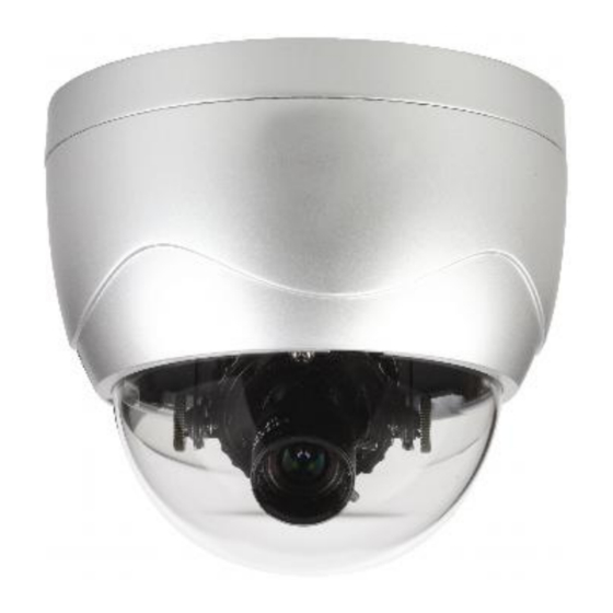
6. Power Supply, Lens and SD card are Optional. 2.1 Panels Description 2.1.1 Side Elevation of the IP-CAM705 Dome Housing Dome Cover Lens Fig 2.1.1 Side Elevation of IP-CAM705 series camera... -
Page 7: Rear Panel Description
Rear Panel of IP-CAM705 series Address& protocols dial switch. Define for dial switch: from 1 to 5. Dial switch function as follows: Switch Function SHARP SOFT NAGC SAGC Note: The dipswitches from 6 to 10 are not used on the IP-CAM705... -
Page 8: Product Installation
Product Installation Fig 2.2.4 Place card template to mark fixing holes Fig 2.2.5 Fix securing plate Position the three location pegs on the Dome camera into the three fixing slots on the securing plate. Ensure that the alignment marks correspond when the dome is fitted and then turn anti-clockwise to lock. -
Page 9: Parameter Configuration
Parameter Configuration There are several network parameters that need setting after the hardware installation. These parameters include IP address, subnet mask and port number, etc., which can be set by various means and two of them are detailed below. Set the camera parameters such as IP address and PPPOE through IE. Set the camera parameters through the client software. -
Page 10: Fig 3.1.1 Login Interface
Fig. 3.1.1 Login Interface Fig. 3.1.2 Preview Interface... -
Page 11: Fig 3.1.3 Remote Parameters Config
It supports Playback and Log functions. To set the camera parameters through IE browser, click Config and wait for the Remote Parameters Config dialogue box to display and then set the parameters such as IP address, etc. as required. For more specific information regarding Remote Parameters Config, please refer to the Client Software in remote-distance parameter settings. -
Page 12: Parameter Configuration Through Client Software
3.2 Parameter Configuration through Client Software Please refer to the client software instruction manual on the CD supplied with your I.P camera. Parameter Configuration through DVR9K Before configuration, please make sure that IP cameras are already connected to the same network. -
Page 13: Wan Access
WAN Access IP cameras have their own network capability and can be connected direct through a network for viewing only. In most circumstances however they would be connected through a DVR and do not have to be setup in the modem/router. If they are used independently then each IP camera must be allocated a unique IP address but can use the same port number. -
Page 14: Wan Access With A Dynamic Ip Address Not Connected Through A Dvr
WAN Access with a dynamic IP address not connected through a DVR By setting Register in client software to Normal Domain, a dynamic name can be entered in Domain name box. Of course the dynamic name must be registered with a dynamic IP site such as www.dydns.com. -
Page 15: Common Failures And Maintenance
Common failures and maintenance 5.1. Power on failure Check if the power plug is fixed into the socket and if the power supply is working correctly. 5.2. Image blurred Check if the lens connector is correct. There are two types lens mounts i.e C and CS which are different. -
Page 16: Technical Specifications For Ip-Cam705
Technical Specification for IP-CAM705 Parameter Model IP-CAM705 Image Sensor 1/4 inch CMOS Effective Pixels 640(H)×480(V) Lens 3.5-8mm/F1.6/M12/ manual Iris lens Min. Illumination 0.4Lux/F1.2 Video Output 1.0Vp-p Composite Output(75 /BNC) Day&Night Electronic Video Compression H.264/MPEG-4 Video Output 32 K 2M, adjustable(8Mbps maximum)
Need help?
Do you have a question about the IP-CAM705 and is the answer not in the manual?
Questions and answers