Table of Contents
Advertisement
Quick Links
Advertisement
Table of Contents

Related Manuals for System Q IP-CAM750


Summary of Contents for System Q IP-CAM750
-
Page 1: Ip Dome Camera
IP Dome Camera IP Network Camera User Manual Model IP-CAM750 Version 1.0.0... -
Page 2: Safety Instructions
Safety Instruction These instructions are intended to ensure that user can use the product correctly to avoid danger or property loss. The precaution measure is divided into “ Warnings” and “ Cautions” Warnings: Serious injury may be caused if warnings are neglected. Cautions: Injury or equipment damage may be caused if cautions are neglected. -
Page 3: Cautions
Cautions 1. Make sure the power supply voltage is correct before using the camera. 2. Do not drop the camera or subject it to physical shock. 3. Do not touch the CMOS sensor with your fingers. If cleaning is necessary, use clean dry cloth. -
Page 4: Table Of Contents
1. Introduction 1.1 Network camera Functions and Features 2. Installation 2.1 Panels Description 2.1.1 Side Elevation of IP-CAM750 series camera 2.1.2 Rear Panel Description Product Installation Fig 2.2.1. Place card template to mark fixing holes Fig 2.2.2 Fix securing plate Fig 2.2.3 Dome Camera fixing... -
Page 5: Introduction
1.1 Network camera Functions and Features The IP-CAM750 series network cameras support the E-PTZ function. The IP-CAM750 series cameras have an OSD menu that can be displayed on screen by entering a 95 CALL via the client software or Internet Explorer. -
Page 6: Installation
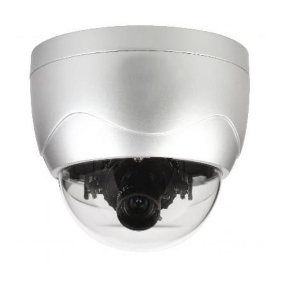
6. Power Supply, Lens and SD card are Optional. 2.1 Panels Description 2.1.1 Side Elevation of the IP-CAM750 Dome Housing Dome Cover Lens Fig 2.1.1 Side Elevation of IP-CAM750 series camera... -
Page 7: Rear Panel Description
Rear Panel of IP-CAM750 series Address& protocols dial switch. Define for dial switch: from 1 to 5. Dial switch function as follows: Switch Function SHARP SOFT NAGC SAGC Note: The dipswitches from 6 to 10 are not used on the IP-CAM750... -
Page 8: Product Installation
Product Installation Fig 2.2.1 Place card template to mark fixing holes Fig 2.2.2 Fix securing plate Position the three location pegs on the Dome camera into the three fixing slots on the securing plate. Ensure that the alignment marks correspond when the dome is fitted and then turn anti-clockwise to lock. -
Page 9: The Ip-Cam750 Series Cameras
The IP-CAM750 series cameras 2.4.1 The E-PTZ function Under the resolution of QCIF/CIF/DCIF/2CIF/VGA/D1/SVGA, the pan\tilt\zoom operation is supported. Note that the pan and tilt operation can only be carried out after zooming in. These cameras support 127 preset positions (preset 95 is excluded as it is used to call the menu). - Page 10 <MAIN MENU > LANGUAGE CHINESE/ENGLISH FLICKER CONTROL 50Hz RESOLUTION FRAME 25fps SHUTTER AUTO GAIN DAY/NIGHT Auto WHITE BALANCE Auto EFFECTS MODE MIRROR EPTZ <EXIT> <SAVE> Select OSD menu by PTZ control key, as follows: U P : Means select OSD menu item DOWN : Means select OSD menu item LEFT : Means select parameter on OSD...
- Page 11 Iris means Enter. You can select Save, Cancel or Preset according to the exit options.
-
Page 12: Menu Operations
Menu Operations The menu selection is implemented through the Up, Down, Left and Right buttons. You can select the menu function by Up or Down buttons and enter the specified function by the Left or Right buttons. LANGUAGE CHINESE ENGLISH Switch CHINESE/ENGLISH by Left or Right buttons FLICKER CONTROL 50Hz... - Page 13 This option is used for displaying the output frame rate but cannot be controlled by the Left or Right buttons. SHUTTER Default Shutter Exposure AUTO×2 Longer Shutter Exposure AUTO×5 Maximum Shutter Exposure 50Hz 60Hz Resolution Auto×2 Auto×5 Auto×2 Auto×5 DCIF QCIF 4CIF 25fps...
- Page 14 AUTO GAIN MEDIUM HIGH You can set up different auto gain values in low light conditions and increase the picture brightness. This function not only operates independently, but also can be used in conjunction with the shutter option, to achieve better low light illumination effects. DAY/NIGHT Auto Color...
- Page 15 In low illumination conditions, the auto mode has a better noise cut-off effect compared with colour mode. WHITE BALANCE AUTO Enable the auto W&B of the current screen Based on the current W&B state - no more auto adjustment. EFFECTS MODE SEPIA NEGATIVE SOLARIZE1...
- Page 16 MIRROR LEFT RIGHT UP BOTTOM CENTER...
- Page 17 EPTZ Supports mechanical PTZ only Supports EPTZ function only EXIT SAVE Saves the current configuration CANCEL Reverts to previous configuration DEFAULT Restores to the default configuration This mode is employed after clicking “ enter” buttons.
- Page 18 Parameter Configuration There are several network parameters that need setting after the hardware installation. These parameters include IP address, subnet mask and port number, etc., which can be set by various means and two of them are detailed below. Set the camera parameters such as IP address and PPPOE through IE. Set the camera parameters through the client software.
- Page 19 Fig. 4.1.1 Login Interface Fig. 4.1.2 Preview Interface...
- Page 20 It supports Playback and Log functions. To set the camera parameters through IE browser, click Config and wait for the Remote Parameters Config dialogue box to display and then set the parameters such as IP address, etc. as required. For more specific information regarding Remote Parameters Config, please refer to the Client Software in remote-distance parameter settings.
-
Page 21: Parameter Configuration Through Client Software
4.2 Parameter Configuration through Client Software Please refer to the client software instruction manual on the CD supplied with your I.P camera. Parameter Configuration through DVR9K Before configuration, please make sure that IP cameras are already connected to the same network. -
Page 22: Wan Access
WAN Access IP cameras have their own network capability and can be connected direct through a network for viewing only. In most circumstances however they would be connected through a DVR and do not have to be setup in the modem/router. If they are used independently then each IP camera must be allocated a unique IP address but can use the same port number. -
Page 23: Wan Access With A Dynamic Ip Address Not Connected Through A Dvr
WAN Access with a dynamic IP address not connected through a DVR By setting Register in client software to Normal Domain, a dynamic name can be entered in Domain name box. Of course the dynamic name must be registered with a dynamic IP site such as www.dydns.org. -
Page 24: Common Failures And Maintenance
Common failures and maintenance Power on failure Check if the power plug is fixed into the socket and if the power supply is working correctly. Image blurred Check if the lens connector is correct. There are two types lens mounts i.e C and CS which are different. - Page 25 Technical Specification for IP-CAM750 Model IP-CAM750 Image Sensor 1/3 inch CMOS Effective Pixels 1600(H)×1200(V) Lens 2.8-11mm,F1.4 manual Iris lens Min. Illumination 0.5Lux/F1.2 0.1Lux/F1.2, sensitization X5 Video Output 1.0Vp-p Composite Output(75 /BNC) Day&Night Electronic Video Compression H.264/MPEG-4 Video Output 32 K 2M, adjustable(8Mbps maximum)
Need help?
Do you have a question about the IP-CAM750 and is the answer not in the manual?
Questions and answers