Table of Contents
Advertisement
Operating Instructions
(Turbomatic 28 - 55 kW)
(Turbomatic 70 - 100 kW)
Turbomatic TMC 28-100
(with Lambdatronic H 3200)
Be sure to read and comply with the operating instructions and safety
information
Subject to technical change.
Fröling Heizkessel- und Behälterbau Ges.m.b.H
Industriestraße 12
A-4710 Grieskirchen
Tel +43 (0) 7248 606-0
Fax +43 (0) 7248 606-600
info@froeling.com
www.froeling.com
Advertisement
Table of Contents

Related Manuals for Froling Turbomatic 28 - 55 kW


Summary of Contents for Froling Turbomatic 28 - 55 kW
-
Page 1: Operating Instructions
Operating Instructions (Turbomatic 28 - 55 kW) (Turbomatic 70 - 100 kW) Turbomatic TMC 28-100 (with Lambdatronic H 3200) Be sure to read and comply with the operating instructions and safety information Subject to technical change. Fröling Heizkessel- und Behälterbau Ges.m.b.H Industriestraße 12... - Page 3 Introduction Dear customer, Congratulations on choosing a quality product from FRÖLING. The FRÖLING Turbomatic waste wood boiler features a state-of-the-art design that conforms to all currently applicable standards and testing guidelines. Please read and observe the operating instructions and always keep them close to the boiler for reference.
-
Page 4: Table Of Contents
Contents 1 Product Overview 2 Safety 2.1 Safety Information 2.2 Permitted Uses 2.2.1 Permitted fuels ....................9 Wood chips ....................9 Pellets ......................10 Shavings..................... 10 Miscanthus ....................10 Changing the fuel..................11 2.2.2 Non-permitted fuels ..................11 2.2.3 Who may operate the boiler? ................11 2.3 Design Information 2.3.1 Approval and obligation to report .............. - Page 5 Contents 3.4 Emergency firewood operation 3.4.1 Modifying the boiler for emergency firewood operation ........25 3.4.2 Setting the controller for emergency firewood operation ........27 3.4.3 Filling the boiler with firewood................. 28 3.5 Modifying the boiler for normal operation 4 Boiler servicing 4.1 General information on servicing 4.1.1 Service mode ....................
-
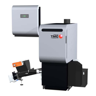
Page 6: Product Overview
Product overview 1 Product overview Page 6 B 059 00 08... - Page 7 Product overview Pos. Description Symb. Wood chip boiler - Fröling Turbomatic Switch cabinet with integrated Lambdatronic H 3200 controller Main switch: switch the power supply on and off for the entire system Control panel of the Lambdatronic H 3200 controller Status LED (operating status): - slow green flashing light: boiler activated - fast green flashing light: boiler deactivated - red flashing light: Fault...
-
Page 8: Safety
Safety Safety information 2 Safety 2.1 Safety information DANGER Non-permitted use! Incorrect use of the boiler can cause severe injuries and damage! The instructions and information provided in the instructions should be observed! Details on procedure for operation, maintenance and cleaning, as well as troubleshooting for the boiler are included in the individual instructions. -
Page 9: Permitted Uses
Safety Permitted uses 2.2 Permitted uses The boiler should only be operated when it is in full working order. It should be operated in accordance with the instructions, observing safety precautions, and you should ensure you are aware of the potential hazards. -
Page 10: Pellets
Safety Safety information Pellets Wood pellets made from natural wood with a diameter of 6 - 10 mm Exception: When using a pellet suction system the maximum diameter is of the wood pellets is limited to 6 mm. § Applicable Standards: Austria: ÖNORM M 7135 - HP 1 and/or DINplus certification program... -
Page 11: Changing The Fuel
Safety Permitted uses Changing the fuel CAUTION Incorrectly set fuel parameters: Incorrect parameter settings have a significant effect on the functioning of the boiler, and as a result this will void the guarantee. If the fuel is changed (e.g. from wood chips to pellets), the system must be reset by Fröling customer services. -
Page 12: Design Information
Safety Design information 2.3 Design information It is forbidden to carry out modifications to the boiler or to change or deactivate safety equipment. Always comply with all fire, building, and electrical regulations when installing or operating the boiler system, in addition to following the operating instructions and mandatory regulations that apply in the country in which the boiler is operated. -
Page 13: Ventilation Of Boiler Room
Safety Design information 2.3.3 Ventilation of boiler room The openings for the supply air and the exhaust air should be arranged as close to opposite each other as possible to achieve a good thermal draught effect. The supply air must be drawn in directly from outside. Exhaust air must be discharged directly outside. -
Page 14: Return Feed Lift
Safety Design information Return feed lift If the hot water return feed is below the minimum return feed temperature, some of the hot water outfeed will be mixed in. CAUTION Risk of dropping below dew point/condensation formation if operated without return feed lift. Condensation water forms an aggressive condensate when combined with combustion residue, leading to damage to the boiler. -
Page 15: Draught Limiter
Safety Design information Draught limiter We recommend that a draught limiter is fitted (A) Install the draught limiter directly under the mouth of the flue line, as there is always low pressure there. Boiler data for constructing the flue gas system: Description Units Flue gas temperature... -
Page 16: Safety Devices
Safety Safety devices 2.4 Safety devices Automatic operation button If the boiler overheats: Press and hold the button for 5 seconds Automatic operation is switched off and the controller follows the boiler shutdown procedure The pumps continue to run! Never use the main switch. Safety temperature limiter (back Page 17, of boiler) -
Page 17: Devices For Preventing The Boiler From Overheating
Safety Safety devices 2.4.1 Devices for preventing the boiler from overheating Thermal discharge safety device At around 100 °C a valve opens and sends cold water to the safety heat-exchanger to decrease the temperature. Safety Temperature Limiter STL Stops combustion at a max. boiler temperature of 105 °C. The pumps continue to run. -
Page 18: Residual Risks
Safety Emergency procedure 2.6 Residual risks WARNING Touching hot surfaces! Hot parts and the flue pipe can cause serious burns! It should be standard practice to wear protective gloves when working on the boiler. Only operate the boiler using the handles provided for this purpose. -
Page 19: Emergency Procedure
Safety Residual risks 2.7 Emergency procedure 2.7.1 Overheating of the system If the system overheats in spite of the safety devices, proceed as follows: Keep all the doors on the boiler closed. Turn off the boiler by pressing the button for 5 seconds Under no circumstances use the main switch! Open all mixer taps, switch on all pumps. -
Page 20: Operating The System
Operating the system Initial start-up / loading fuel 3 Operating the system 3.1 Initial start-up NOTICE Optimum efficiency and efficient, low-emission operation can only be guaranteed if the system is set up by trained professionals and observing the standard factory settings. Take the following precautions: Initial start-up should be carried out with an authorised installer or with Fröling customer services. -
Page 21: Loading Wood Chips In A Partially Emptied Store
Operating the system Initial start-up / loading fuel 3.2.1 Loading wood chips in a partially emptied store If there is still sufficient fuel in the store (the head of the stirrer is completely covered with fuel), the store can be filled: Load the fuel at the filling opening 3.2.2 Loading wood chips in an empty store... -
Page 22: Blowing In Pellets For A Store With Pellet Screw
Operating the system Initial start-up / loading fuel 3.2.3 Blowing in pellets for a store with pellet screw For systems with a pellet screw, the boiler must be in “OFF” status when the store is filled. The under-pressure from the blowing could bring smoke back into the store. -
Page 23: Blowing In Pellets For An Empty Store With Stirrer
Operating the system Initial start-up / loading fuel 3.2.5 Blowing in pellets for an empty store with stirrer CAUTION! If the head of the stirrer is already free of material and the arms / spring blades are extended, then the feeder unit must be active during the filling process, however the boiler must be in “OFF”... -
Page 24: Heating Up The Boiler
Operating the system Heating up the boiler 3.3 Heating up the boiler 3.3.1 Switching on the system Turn the main switch on the side of the switch cabinet to the “ON” position After the system check by the controller, the system is ready for operation “Boiler Off”... -
Page 25: Emergency Firewood Operation
Operating the system Heating up the boiler 3.4 Emergency firewood operation CAUTION Incorrect emergency firewood operation Damage to the boiler is possible! The following points must be observed for emergency firewood operation: Operate only in exceptional cases We accept no responsibility for damage caused by continuous emergency operation! Connect a thermal discharge safety device to the safety battery Feed based on output... - Page 26 Operating the system Heating up the boiler When the boiler has cooled off: Remove the burn-out opening from the combustion chamber Push the guide plates in the U-profiles up and remove Check the guide plates for dirt. Clean where necessary. Insert the burn-out plate with the cutouts (1) behind the U-profiles Insert the guide plates at the U-...
-
Page 27: Setting The Controller For Emergency Firewood Operation
Operating the system Heating up the boiler 3.4.2 Setting the controller for emergency firewood operation For emergency firewood operation, the mode must be set to “Firewood operation” on the controller: Call up the “Mode” menu repeatedly In the mode menu: Press the button A “?”... -
Page 28: Filling The Boiler With Firewood
Operating the system Heating up the boiler 3.4.3 Filling the boiler with firewood Open the insulating door and combustion chamber door Combustion air blower fan and induced draught fan switch on Put a layer of firewood onto the emergency grate Put crumpled paper and firewood on top of it Arrange the required quantity of firewood lengthwise... -
Page 29: Boiler Servicing
Boiler servicing Inspection, cleaning and maintenance 4 Boiler servicing 4.1 General information on servicing DANGER Working on electrical components Risk of serious injuries from electric shocks Work on electrical components should only be carried out by authorised technicians WARNING Non-permitted cleaning and maintenance! Incorrect or insufficient cleaning and maintenance of the boiler can cause serious faults in combustion (e.g. -
Page 30: Service Mode
Boiler servicing Inspection, cleaning and maintenance 4.1.1 Service mode Service mode should be activated for maintenance work on the boiler: Press and hold the button for 5 seconds The controller follows the shutdown procedure and starts with the cleaning cycle. After the cleaning cycle the boiler goes to the operating status, “Cleaning possible”... -
Page 31: Inspection, Cleaning And Maintenance
Boiler servicing Inspection, cleaning and maintenance 4.2 Inspection, cleaning and maintenance Regular cleaning of the boiler extends its life and is a basic requirement for smooth running based on output. So clean the boiler regularly! 4.2.1 Inspection Checking the ash level The ash box must be emptied at the correct interval according to energy requirements and fuel quality. -
Page 32: Checking The Thermal Discharge Safety Device
Boiler servicing Inspection, cleaning and maintenance Checking the thermal discharge safety device Check the seal of the discharge valve The discharge pipe must not drip Exception: boiler temperature > 95 °C If water is dripping from the discharge pipe: Clean the discharge safety device or have the installer replace it if necessary Check the safety valve as per the manufacturer’s specifications... -
Page 33: Monthly Cleaning
Boiler servicing Inspection, cleaning and maintenance 4.2.2 Monthly cleaning Cleaning the combustion chamber Open the insulating door and combustion chamber door Remove the burn-out opening Remove the dirt on the burn-out opening with a brush Take out the ash baffle on the back of the combustion chamber and clean Remove soot that has built up on the... -
Page 34: Removing Ash From The Cleaning System
Boiler servicing Inspection, cleaning and maintenance Removing ash from the cleaning system For Turbomatic 28-55 Open the side cleaning door and remove the ash We recommend that you use an ash vacuum. For optional automatic heat exchanger ash removal unit: Empty rear ash box (1) Cleaning the flue gas sensors On flue gas pipe:... -
Page 35: Annual Check
Boiler servicing Inspection, cleaning and maintenance 4.2.3 Annual check Carry out annually, or at least after 1500 hours of operation! The following applies for the annual check: Turn off the main switch on the switch cabinet when the boiler has cooled off Cleaning the smoke flue pipe Clean the connecting pipe between the boiler and the chimney regularly with a chimney sweeping brush... -
Page 36: Cleaning The Combustion Air Blower Fan
Boiler servicing Inspection, cleaning and maintenance Cleaning the combustion air blower fan Unscrew 4 screws on the blower fan and take off the protective grating Clean the running wheel and protective grating (cloth, compressed air, ...) Put the protective grating back on and fix with screws Switch the main switch on the switch cabinet back on... -
Page 37: Instructions For Measuring Emissions
Boiler servicing Inspection, cleaning and maintenance 4.3 Instructions for measuring emissions 4.3.1 Measurement at rated load For the highest possible heat consumption: - Ensure that heating pumps are switched on - Open mixer valves and radiator valves - Set the DHW tank loading time to the current time - Set the boiler temperature setpoint to 85°C Chimney sweep mode takes over this function Activating chimney-sweep mode... -
Page 38: Maintenance Agreement / Customer Service
Boiler servicing Inspection, cleaning and maintenance 4.4 Maintenance agreement / Customer service Long service life with a service agreement! Regular maintenance and servicing by a heating specialist will ensure a long, trouble-free service life for your heating system. It will ensure that your system stays environmentally-friendly and operates efficiently and cost-effectively. -
Page 39: Troubleshooting
Troubleshooting 5 Troubleshooting 5.1 General faults in the power supply Error characteristics Cause of error Error correction Nothing is shown on the • General power failure display • FI circuit breaker or line Switch on the FI circuit breaker or No power to the controller protection is switched off line protection... -
Page 40: Faults With Fault Message
Troubleshooting 5.3 Faults with fault message If a fault has occurred and has not yet been cleared: Status LED (1) flashes red A fault message is shown on the display (2) An internal distinction is made between 2 types of message: Warning Boiler follows shutdown procedure Error... -
Page 41: Appendix
Appendix Manufacturer’s guarantee conditions 6 Appendix 6.1 Guarantee Conditions Our sale and delivery conditions generally apply. These conditions have been made available to customers, and customers have been made aware of them at the time of order completion. You can also find the guarantee conditions on the enclosed guarantee certificate. -
Page 42: Declaration Of Conformity
Appendix Declaration of Conformity 6.3 Declaration of Conformity EU DECLARATION OF CONFORMITY Product: Wood chip and pellet burner with automatic loading Types: Turbomatic 28, Turbomatic 35, Turbomatic 48, Turbomatic 55, Turbomatic 70, Turbomatic 85, Turbomatic 100, Turbomatic 110 with feeder systems Bottom stirrer (BRK), spring blade stirrer (FBR), articulated arm delivery unit (GLA), pellet screw, pellets suction system EC Directives:... - Page 43 Your Notes Fröling Heizkessel- und Behälterbau Ges.m.b.H Industriestraße 12 A-4710 Grieskirchen Page 43 Tel +43 (0) 7248 606-0 Fax +43 (0) 7248 606-600 info@froeling.com www.froeling.com B 059 00 08...
Need help?
Do you have a question about the Turbomatic 28 - 55 kW and is the answer not in the manual?
Questions and answers