Table of Contents
Advertisement
Quick Links
Installation Instructions
T4 – 24-110
English version of the assembly instructions for technicians.
Read and follow the instructions and safety instructions!
Subject to technical change.
Fröling Heizkessel- und Behälterbau Ges.m.b.H, Industriestrasse 12, A-4710 Grieskirchen
Tel +43 (0) 7248 606-0 Fax +43 (0) 7248 606-600
info@froeling.com www.froeling.com
Advertisement
Table of Contents

Subscribe to Our Youtube Channel
Related Manuals for Froling T4 60


Summary of Contents for Froling T4 60
-
Page 1: Installation Instructions
Installation Instructions T4 – 24-110 English version of the assembly instructions for technicians. Read and follow the instructions and safety instructions! Subject to technical change. Fröling Heizkessel- und Behälterbau Ges.m.b.H, Industriestrasse 12, A-4710 Grieskirchen Tel +43 (0) 7248 606-0 Fax +43 (0) 7248 606-600 info@froeling.com www.froeling.com... -
Page 3: Guarantee Conditions
Introduction Dear customer, The FROLING T4 wood chip boiler features a state-of-the-art design that conforms to all currently applicable standards and testing guidelines. Please read and follow the installation instructions. They contain safety instructions and comprehensive information relating to transporting, setting up and assembling the boiler. -
Page 4: Table Of Contents
1.4.4 Chimney connection/chimney system ..............10 Draught limiter....................10 Boiler data for constructing the flue gas system (T4 24-50) ......... 10 Boiler data for constructing the flue gas system (T4 60-110)........ 11 2 Technology 2.1 Dimensions - T4 2.2 Technical specifications 3 Assembly 3.1 Transport... -
Page 5: Fröling Heizkessel- Und Behälterbau Ges.m.b.h, Industriestraße 12, A-4710 Grieskirchen, Austria
Contents 4.3 Disassembly 4.4 Disposal Fröling Heizkessel- und Behälterbau Ges.m.b.H, Industriestraße 12, A-4710 Grieskirchen, Austria Page 5 Tel +43 (0) 7248 606-0 Fax +43 (0) 7248 606-600 info@froeling.com www.froeling.com M1210512_en... -
Page 6: General Information
General Standards, personnel, design 1 General Information 1.1 Standards The installation and commissioning of the boiler must be carried out in accordance with local fire and building regulations. The following standards and regulations should be observed in any case: ÖNORM/DIN EN 303-5 Boilers for solid fuels, manually and automatically fed combustion systems;... -
Page 7: Qualification Of Assembly Staff
Assembly, installation, initial startup and servicing must only be carried out by qualified people: Heating technicians / building technicians Electrical installation technicians Froling customer services The assembly staff must have read and understood the instructions in the documentation. 1.3 Protective equipment for assembly staff You must ensure that staff have the protective equipment specified by accident prevention regulations. -
Page 8: Information On The Installation Room (Boiler Room)
General Standards, personnel, design The appropriate supervisory authority (inspection agency) must always be informed when installing or modifying a heating system, and authorisation must be obtained from the building authorities: - Austria: Report to the construction authorities of the community or magistrate - Germany: Report new installations to an approved chimney sweep / the building authorities. -
Page 9: Combination With Storage Tank
For the correct dimensions of the storage tank and the line insulation (in accordance with ÖNORM M 7510 or guideline UZ37) please consult your installer or Froling. Return lift If the hot water return is below the minimum return temperature, some of the hot water outfeed will be mixed in. -
Page 10: Chimney Connection/Chimney System
General Standards, personnel, design 1.4.4 Chimney connection/chimney system EN 303-5 specifies that the entire flue gas system must be designed to prevent, wherever possible, damage caused by seepage, insufficient feed pressure and condensation. Please note in this respect that flue gas temperatures lower than 160K above room temperature can occur in the permitted operating range of the boiler. -
Page 11: Boiler Data For Constructing The Flue Gas System (T4 60-110)
General Standards, personnel, design Boiler data for constructing the flue gas system (T4 60-110) Description Unit Flue gas temperature °C Flue gas mass flow 166,2 207,8 255,6 277,2 298,8 kg/h 62,3 75,4 97,2 104,4 Flue gas mass flow 0,046 0,058... -
Page 12: Technology
Technology Dimensions - T4 2 Technology 2.1 Dimensions - T4 Item Description Unit 24/30 40/50 60/75 90/100/110 Height of boiler 1390 1620 1620 1720 Total height including flue gas 1440 1670 1670 1770 pipe connection Height, outfeed connection 1195 1425 1425 1530 Boiler outfeed connection... -
Page 13: Technical Specifications
Technology Technical specifications 2.2 Technical specifications Description Unit Rated heat output Heating efficency range 7,2-24,0 9,0-30,0 12,0-40,0 15,0-50,0 Electrical connection 400V / 50Hz / C20A Electrical consumption 45 - 115 54 - 142 51 - 150 47 - 158 Boiler weight Boiler water capacity Upstream resistence (ΔT= 10 / 20°C) mbar... - Page 14 Technology Technical specifications Description Unit Rated heat output Heating efficiency range 18 – 60 22,5 – 75 27 – 90 30 – 100 33 - 110 Electrical connection 400V / 50Hz / C20A Electrical consumption 51 - 176 56 - 204 61 - 232 65 - 250 65 - 250...
-
Page 15: Assembly
Assembly Transport 3 Assembly 3.1 Transport The boiler comes in cardboard packaging on 2 pallets together with the fuel outfeeder. Move the boiler without jarring or jolting Consult the delivery information on the packaging. 3.1.1 Positioning Position a lifting truck or similar lifting device with an appropriate ... -
Page 16: Positioning Using A Crane (T4 60-110)
Assembly Set-up in the boiler room Positioning using a crane (T4 60-110) Remove the insulating cover and the insulating mat The lifting eye bolts (E) for the boiler is in front of heat-exchanger cover plate below the mat ... -
Page 17: Minimum Distances In The Boiler Room
Assembly Set-up in the boiler room 3.2.3 Minimum distances in the boiler room The boiler should always be set up so that it is fully accessible to allow fast and easy maintenance. Observe the applicable standards and regulations when setting up the boiler. -
Page 18: Assembly Work
Assembly Assembly work 3.3 Assembly work 3.3.1 Installing the ash container Open the clamps on the ash container cover and remove the cover Remove the items included with delivery from the ash container Open the insulating door and pull the locking lever up ... -
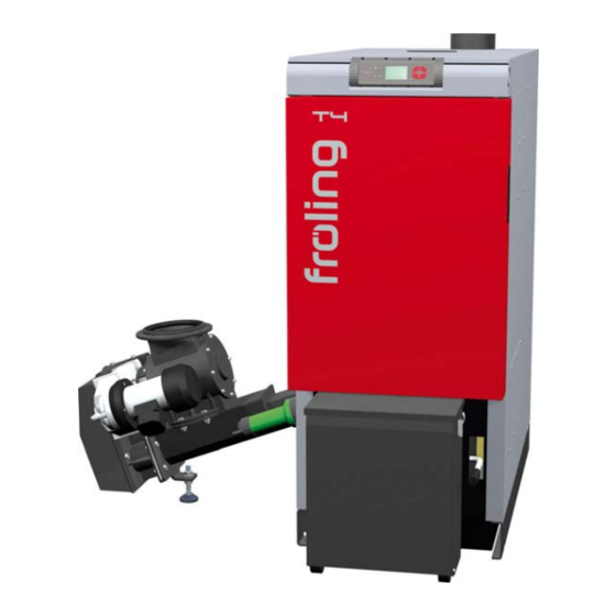
Page 19: Installing The Stoker Unit
Assembly Assembly work 3.3.2 Installing the stoker unit Remove the upper and lower shutter mask on the stoker side Remove the pre-installed screws on the connection flange Position the stoker unit by the boiler as shown Push the stoker unit up to the boiler and insert the two lock bolts ... -
Page 20: Electrical Connection
Remove the locking screws on the controller cover Push the controller cover back and then lift away At T4 60-110: After removing the locking srews move both covers backward an then lift up the controller cover (= front part) -
Page 21: Laying Cables
Assembly Electrical connection 3.4.2 Laying cables Lay the stoker drive and ignition fan cables and the connection cable for the delivery system in the cable duct from the stoker unit to the boiler: Remove the cover of the cable duct on the stoker duct ... -
Page 22: Mains Connection
Assembly Electrical connection 3.4.3 Mains connection Press the mains plug to release it and remove Open the plug and connect the mains connection cable Wiring should be installed using flexible sheathed cable and dimensioned in compliance with the locally applicable standards and guidelines ... -
Page 23: Commissioning / Decommissioning
Take the following precautions: We recommend that the system is commissioned by Froling customer services or an authorised installer. Before heating up the boiler for the first time: Set the controller to match your heating system.
Need help?
Do you have a question about the T4 60 and is the answer not in the manual?
Questions and answers