Froling P4 Installation Manual
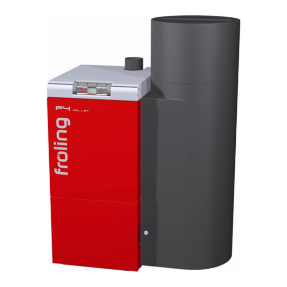
P4 wood pellet boiler
Hide thumbs
Also See for P4:
- Owner's manual (51 pages) ,
- Operating instructions manual (39 pages) ,
- Assembly instructions manual (35 pages)
Table of Contents
Advertisement
Quick Links
Advertisement
Table of Contents

Related Manuals for Froling P4


Summary of Contents for Froling P4
- Page 1 Installation Manual P4 Wood Pellet Boiler Report # 456-S-02-2 Certified to U.S. Standard: UL 2523-2009 Read and follow the operating instructions and safety information! Subject to technical change! Froling GmbH, Industriestrasse 12, A-4710 Grieskirchen, Austria www.froling.com...
- Page 2 Reprinted August 2014 Catalog # P4I2014...
- Page 3 Introduction Dear installer, The FRÖLING P4 Pellet boiler is a state-of-the-art design that conforms to all currently applicable standards and testing guidelines. Please read and follow the assembly instructions. They contain safety instructions and comprehensive information relating to transporting, setting up and assembling the boiler.
-
Page 4: Table Of Contents
Contents 1 General information 1.1 Installation Hazards 1.2 Boiler Installation 1.2.1 Planning ......................7 Sizing the Boiler ..................... 7 Choosing an Installer ..................7 Locating the Boiler and Boiler Clearances ............7 1.2.2 Approvals and reporting obligations ..............8 1.2.3 Requirements for initial filling and re-filling of heating system ......... 8 1.2.4 Outside Combustion Air .................. - Page 5 5.7 Supply and Return Connections 5.8 Plumbing Schematics 5.8.1 Thermal storage sizing ..................52 5.8.2 For systems with thermal storage ..............52 5.8.3 For systems without thermal storage ..............54 Froling GmbH, Industriestrasse 12, A-4710 Grieskirchen, Austria Page 5 www.froeling.com...
-
Page 6: General Information
General Standards, Design, Assembly 1 General information It is unlawful to carry out modifications to the boiler or to change or deactivate safety equipment. In addition to the operating instructions and the applicable national and local codes and regulations for installation and operation of the boiler system, all fire, police, and electrical regulations must be observed. -
Page 7: Boiler Installation
The boiler must be installed with the minimum installation clearances to combustible materials outlined below. Clearances may only be reduced by means approved by the regulatory authorities. Minimum installation clearances see chapter 3.1.5 Froling GmbH, Industriestrasse 12, A-4710 Grieskirchen, Austria Page 7 www.froeling.com... -
Page 8: Approvals And Reporting Obligations
General Standards, Design, Assembly 1.2.2 Approvals and reporting obligations IMPORTANT: Install, modify and use only in accordance with manufacturer’s installation & operation manuals. Refer to authorities having jurisdiction for proper installation. Contact local building and fire officials about restrictions and installation inspection in your area. -
Page 9: Combination With Storage Tank
The ventilation system may need to be re-balanced after installation of the Froling P4. N O T E Canadian installations must conform to ANSI/NFPA outside air requirements of 1 sq. -
Page 10: Chimney Connection / Chimney System
1.2.6 Chimney connection / chimney system The chimney is one of the most critical factors in the successful operation of any solid fuel heater, including the Fröling P4 boiler. A good chimney will provide a continuous and dependable draft to pull the exhaust gasses out of the building. -
Page 11: Basic Boiler Data For Layout Of Chimney System
The suction line must be in a single section! The return-air line can be made up of several sections, but potential equalisation must be established throughout the line! Froling GmbH, Industriestrasse 12, A-4710 Grieskirchen, Austria Page 11 www.froeling.com... -
Page 12: Proper Hose Grounding
General Standards, Design, Assembly Proper Hose Grounding When connecting the hose lines to the individual connection pipes, ensure there is proper grounding throughout the line! Expose approximately 1¼” (3 cm) of the earth conductor at the end of the hose line. ... -
Page 13: Technical Data
Technology Components, Connections, and Dimensions 2 Technical Data 2.1 Components and Connections P4 Pellet Pos. Component Unit 8 / 15 20 / 25 32 / 38 48/60 80/100 Boiler outfeed connection 1½ 1½ 1½ Boiler return feed connection 1½ 1½... -
Page 14: Dimensions
Technology Components, Connections, and Dimensions 2.2 Dimensions P4 Pellet Dimensions Description Unit 8 / 15 20 / 25 32 / 38 48/60 80/100 Length, boiler 29⅛ 29⅛ 32¼ 35½ 39⅜ inches Total length inc. induced draught 40⅛ 43¼ 42⅛ 33¾... -
Page 15: Specification Data
Technology Components, Connections, and Dimensions 2.3 Specification Data P4 Pellet Component Unit Rated heat output 35,800 50,800 68,200 85,300 109,000 129,650 163,780 200,000 273,000 341,000 Btu/ 10,500 10,500 20,500 25,600 30,400 30,400 57,300 57,300 82,000 102,000 Heating efficiency range 35,800... -
Page 16: Temporary Storage
Technology Components, Connections, and Dimensions ❒ Position a fork-lift or similar lifting device using the pallet and bring in the boiler. If the boiler cannot be brought in on the pallet: ❒ Remove the cardboard and remove the boiler from the pallet ⇨... -
Page 17: Setting Up The Boiler Room
Technology Components, Connections, and Dimensions 3.2 Setting up the Boiler Room 3.2.1 Removeing the boiler from pallet ❒ Remove packing bands with suitable tools. ❒ Lift off the cardboard. ❒ Remove the transport covers (1) from the insulated door(s) and ash container as well as the cleaning devices (2). -
Page 18: Transporting In The Boiler Room
Technology Components, Connections, and Dimensions 3.2.2 Transporting in the boiler room Position a fork-lift or similar lifting device at the base frame of the boiler and transport it to the designated position. If no lifting device of this type is available: After removing the suction unit thread a carrying belt through the ... -
Page 19: Dismantling For Location Where Positioning Is Difficult
Technology Components, Connections, and Dimensions 3.3 Dismantling for location where positioning is difficult If there is not enough room to bring in the pre-assembled boiler, certain components can be dismantled. This section shows the maximum possible disassembly. Only dismantle the parts absolutely necessary to bring in the boiler. 3.3.1 Removing the stoker assembly and insulation ❒... -
Page 20: Dismantling The Suction Cyclone Cover
Technology Components, Connections, and Dimensions ❒ Remove the screw and lock washer on the bottom of the controller cover. ❒ Remove the controller cover. 3.3.2 Dismantling the suction cyclone cover ❒ Remove the covering of the middle cable duct. At the pellet module: ❒... -
Page 21: Dismantling The Stoker Unit
Technology Components, Connections, and Dimensions ❒ Wind up the unplugged cables. ❒ Open the clamps and take off the cover. 3.3.3 Dismantling the stoker unit ❒ Remove the covering of the cable duct. At the pellet module: ❒ Unplug the components: ▪... - Page 22 Technology Components, Connections, and Dimensions ❒ Undo the screw and remove the clamp on the igniter. ❒ Remove the igniter. ❒ Remove the cotter pin at the front and back of the grate drive and remove the bolts. CAUTION: Secure the grate motor so that it does not fall! ...
-
Page 23: Notes For Reassembly
Notice! The following steps require two people: ▪ Weight of stoker unit P4 Pellet 80 - 100: approx. 31 lbs. ❒ Pull the stoker unit up slightly until the hooks come out of the stoker flange. -
Page 24: Assembling The Pellet Boiler
Technology Components, Connections, and Dimensions Igniter ❒ Fit the clamp to the igniter tube using screws Fix the cable with the cable ties supplied. There must not be any loose cables in the area of the igniter. Only connect the power supply after completing assembly. ... - Page 25 Technology Components, Connections, and Dimensions Adjusting the doors On the side with the door stop ❒ Using wrench (13 mm), loosen the lock nuts on the locking cams at the top and bottom. ❒ Close the door. With a gap of approx. 5-6” there should be noticeable resistance. ❒...
-
Page 26: Fitting The Ash Container And Doors
Technology Components, Connections, and Dimensions ❒ Loosen the lock nuts at the top and bottom of the locking plate using a wrench (13 mm). ❒ Close the door. With a gap of approx. 5-6” there should be noticeable resistance. ❒... - Page 27 Technology Components, Connections, and Dimensions ❒ Remove the screw and lock washer on the bottom of the controller cover. ❒ Remove the controller cover. ❒ Hang the insulated door to the boiler base and secure with lock bolt. ❒ Take the two covers for the ash containers out of the ash containers, position and secure with clamps.
-
Page 28: Electrical Connection
Components, Connections, and Dimensions 3.5 Electrical connection For the P4 Pellet boiler a 240 VAC, 60 hertz, 4 wire power supply is required. This electrical connection should be from a dedicated 15 amp, circuit breaker. A master service switch for the boiler, mounted on or in the proximity of the boiler, is recommended. -
Page 29: Hydraulic System Module Overview
Technology Components, Connections, and Dimensions 3.5.2 Hydraulic System Module Overview The hydraulic system module makes available the connections of sensors and pumps for the hydraulic components of the system (storage tank, DHW tank...). A hydraulic module is included in the delivery as standard. Hydraulic System Module 3.5.3 Pellet Module Overview The pellet module is included in standard delivery and has the connections for the... -
Page 30: Fan Installation
Technology Components, Connections, and Dimensions 3.5.4 Fan Installation ❒ Remove the locking screws on the sound insulation hood of the stoker assembly and remove the sound insulation hood. ❒ Open the clamps on the suction cyclone container and remove the cover. ❒... -
Page 31: Wire Connections
Technology Components, Connections, and Dimensions 3.5.5 Wire Connections R I S K Working on electrical components. Danger: Serious injuries from electric shocks. Work on electrical components should only be carried out by authorized technicians. Observe the applicable standards and regulations. ... - Page 32 Technology Components, Connections, and Dimensions ❒ Wire the connections in accordance with the schematic diagram. Wire the connections in accordance with the circuit diagram. For circuit diagrams see operating instructions for "Lambdatronic P 3200." Remove screws above and below wire pass-through. ...
- Page 33 Technology Components, Connections, and Dimensions Complete the main connections (L1, L2, N, PE). Plug the circulator(s) into “pump 1 and pump 2” sockets on the Hydraulic System Module board. ⇨ See "Temperature Sensors” [page 52] 1 2 3 4 5 6 Pull any temperature sensor cables through the upper cable duct ...
-
Page 34: Install Delivery System
Installation Install delivery system 3.6 Install delivery system 3.6.1 Universal suction system Variant 2 - Eco Pellet Box Variant 1 - Comfort pellet box 25 m Suction hose Manual re-arranging unit (Variant 2) Hose clamps 50-65 mm 2 Blind plates (Variant 2) 2 Fire protection choke collar 6 Star-shaped handle (Variant 2) (Optional) -
Page 35: Variant 1 - Comfort Pellet Box
Installation Install delivery system Variant 1 - Comfort Pellet Box Position Comfort Pellet Box (D) at hole in the wall. For maintenance purposes, the distance to the wall on the board side of the pellet box 10 cm should be at least 4”... -
Page 36: Variant 2 - Eco Pellet Box
Installation Install delivery system Variant 2 - Eco Pellet Box Place the wall installation module (F) by the hole in the wall. Secure the insertion module to the wall using four M8x50 frame screws and 10 mm Rawlplugs. Pack the space in the hole in the wall with a non- ... -
Page 37: Installing The Suction Probes And Lines
Installation Install delivery system Installing the suction probes and lines Position the suction probes (K) at equal distances in the pellet supply bin. Secure the suction probes to the bottom using frame screws. Fix hose lines (A) to the suction probe using hose ... -
Page 38: Suction Screw System
Installation Install delivery system 3.6.2 Suction screw system Flange bearing Gearbox flange Ejector flange Drive flange seal Trough mount with rubber pad Geared motor Bearing flange 2 Cover plates for wall penetration Open trough Main worm Suction intake with integrated support Shaft end for main worm Proximity switch Worm extension (if needed) - Page 39 Installation Install delivery system Position the main components in the store. (1) Suction piece (2) Basic screw with trough (3) Extension screw(s) with trough (number depends on model) Push suction piece from inside out through the hole in the wall.
- Page 40 Installation Install delivery system Slide the flange plate over the shaft endpiece and screw to the trough. Fit the ejecting flange and flange bearing to the flange plate. The opening of the ejecting flange must face down. Fit the gear flange to the geared motor as ...
- Page 41 Installation Install delivery system Drill holes in the floor with a power drill ( 10mm) and hammer in the nylon plugs). Insert a soundproof washer 18 mm in each of the holes in the adjustable feet and position a soundproof washer ...
-
Page 42: Bag Silo System
Installation Install delivery system Lay the hose lines to the boiler, through identified openings at the back plate and install with hose clamps to the identified connections. WARNING! Read the label on the suction probe or pellet box about the suction line and return-air line! Ensure correct connection! ... -
Page 43: Pellet Storage Area
Installation Install delivery system Lay the hose lines to the boiler, through identified openings at the back plate and install with hose clamps to the identified connections. WARNING! Observe the label for the suction line and the return-air line on the silo suction probe and boiler. -
Page 44: Size Of Storage Area
Installation Install delivery system Size of storage area The storage area should be able to hold approximately ½ the annual requirement. The exact amount of required space depends on the system's heating load. Rule of thumb formula: 1ft³ of pellet storage space per 100 Btu’s of ... -
Page 45: Initial Startup
Initial startup 4 Initial Startup 4.1 General information IMPORTANT: First start up of boiler system shall be carried out only in attendance of an authorized installer or manufacturer’s representative During normal operation of boiler all surfaces and control handles behind insulation door get hot. -
Page 46: Plumbing Systems
5 Plumbing Systems This chapter contains examples of plumbing schematics that are most suitable for the P4 Pellet boiler. They are merely examples and are no substitute for complete system planning. We reserve the right to make technical changes without prior notice. -
Page 47: Bus System
Plumbing Systems 5.2 Bus System 5.2.1 Hydraulic Module Hydraulic module for S/P/H 3200: Wall casing with control PCB for controlling: -2 pumps, using max. 6 sensors -max. 8 units can be used per system 2 immersion sensors are included, which Can be used for the following: -Storage Tank Management: For speed-controlled storage tank loading via 2 sensors. -
Page 48: Sensor Functions For Standard Systems
“Yes”. Option B is for a system where the secondary boiler has independent control. The Froling P4 will not control the boiler setpoints of the secondary boiler. Please refer to Section 4.6.3 Service Parameters for Secondary Boiler. The parameter “Control standby boiler variably to the setpoint”... - Page 49 Plumbing Systems Option A: Oil/Gas boiler Circulator Connections If additional pump connections are needed; mount the optional Hydraulic System Module to wall. Option A: Circulator Wire Connections Please refer to Lambdatronic Operating Instructions Section 6.2.2 Hydraulic System Module for complete wiring instructions. Option B: Circulator/Burner Control Wire Connections (example only) Core Module...
-
Page 50: Pellet Boiler Circulator Pump Connection (Pump 0.1)
Plumbing Systems 5.4.2 Pellet Boiler Circulator Pump Connection (Pump 0.1): -Connect to Pump 1 socket on the Hydraulic board (See Fig 5.1). 5.4.3 DHW Circulator Pump Connection (Pump 0.2) -Connect to Pump 2 socket on the Hydraulic board (See Fig 5.1). 5.4.4 Temperature Sensors (sensor 0.1-0.5) -Connect Temperature sensors to sensors 1 to sensors 6 (See Fig 5.1). -
Page 51: Return Temperature Control (Only For The Model 80/100)
5.7 Supply and Return Connections Please pay attention to connection labeling on back of boiler. For P4 Pellet 8- 38 models the supply connection is the lower connection and on the P4 Pellet 48-100 models the supply connection is the upper connection. Only the P4 Pellet 80/100 will need return temperature control. -
Page 52: Plumbing Schematics
P4 80 pellet P4 100 pellet It is highly recommended that the Fröling P4 pellet boiler is combined with storage tank. This combination has many advantages, including fewer burn starts, reduced wear and lower emissions. Please use the chart above for proper sizing. - Page 53 Plumbing Systems Fröling Heizkessel- und Behälterbau Ges.m.b.H, Industriestrasse 12, A-4710 Grieskirchen Page 53 Tel +43 (0) 7248 606-0 Fax +43 (0) 7248 606-600 info@froeling.com www.froeling.com M0930207...
-
Page 54: For Systems Without Thermal Storage
Constant circulation When no thermal storage is utilized, the P4 Pellet boiler’s circulator is always on at a fixed speed when the boiler is operating. It is crucial to have the proper flow rate through the boiler. Overly high flow rates will reduce output temperatures and low flow rates may cause the boiler to overheat. - Page 55 Plumbing Systems ggggggggggggggggg Fröling Heizkessel- und Behälterbau Ges.m.b.H, Industriestrasse 12, A-4710 Grieskirchen Page 55 Tel +43 (0) 7248 606-0 Fax +43 (0) 7248 606-600 info@froeling.com www.froeling.com M0930207...
Need help?
Do you have a question about the P4 and is the answer not in the manual?
Questions and answers