Table of Contents
Advertisement
Quick Links
Owner's Manual and Instructions
Congratulations!
You have purchased the finest radiant heater available for the heating of livestock
in agricultural animal confinement buildings.
Your new L.B. White radiant heater incorporates the benefits from the most
experienced manufacturer of heating products using state-of-the-art technology.
We, at L.B. White, thank you for your confidence in our products and welcome any
suggestions or comments you may have...call us toll free at (800) 345-7200.
ATTENTION ALL USERS
This heater has been tested and evaluated by L.B. White Co., Inc. as a direct gas-fired
radiant heater with intended use for the heating of livestock in agricultural animal
confinement buildings. If you are considering using this product for any application
other than its intended use, then please contact your fuel gas supplier, or the
L.B. White Co., Inc.
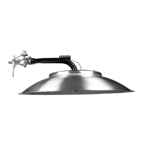
Modulating Infraconic
Agricultural Building Radiant Heaters
MODELS
OUTPUT (Btuh)
40
40,000
I
FUEL
Propane Vapor
Withdrawal
or Natural Gas
150-23199-B
Advertisement
Table of Contents

Related Manuals for L.B. White 140


Summary of Contents for L.B. White 140
- Page 1 (800) 345-7200. ATTENTION ALL USERS This heater has been tested and evaluated by L.B. White Co., Inc. as a direct gas-fired radiant heater with intended use for the heating of livestock in agricultural animal confinement buildings.
- Page 2 Save this Owner’s Manual for future use and reference. Owner’s Manuals and replacement labels are available at no charge. For assistance, contact L.B. White at 800-345-7200. WARNING Proper gas supply pressure must be provided to the inlet of the heater.
-
Page 3: Table Of Contents
Table of Contents SECTION PAGE General Information ..............3 Heater Specifications . -
Page 4: Heater Specifications
These include building ventilation and control systems, building insulation, building size and population density, etc. Consult your L.B. White dealer or call L.B. White for specific recommendations for your application. This is a typical sensor height range for poultry installations. The size and type of livestock being grown, heater spacing and height, etc. -
Page 5: Safety Precautions
Safety Precautions WARNING Asphyxiation Hazard Do not use this radiant heater for heating human living L.B. White Company to determine combustion air quarters. ventilation requirements of the heater. Do not use in unventilated areas. Lack of proper ventilation air will lead to improper combustion. - Page 6 Safety Precautions 1. Do not attempt to install, repair or service this heater 5. This heater is intended for the heating of livestock in or the gas supply line unless you have continuing agricultural animal confinement buildings only. The expert training and knowledge of gas heaters. heater shall only be mounted inside the animal confinement building.
-
Page 7: Installation Instructions
13. The grower shall inspect the heater before building -- Start-up and shut down of the heaters and zone repopulation. Such inspection should consist of, but control panel to test for proper operation. is not limited to, the following points of action: -- Leak check of all pipe joints and hose connections. - Page 8 -- If a leak is detected, check the components 12. The heater is designed for either L.P. vapor with- involved for cleanliness in the thread areas drawal or natural gas, depending on model number. and proper application of pipe compound Do not use this heater in an LPG liquid withdrawal before further tightening.
-
Page 9: Gas Train Assembly
GAS TRAIN ASSEMBLY Your heater is supplied with one of the following gas train assemblies. Refer to the appropriate illustrations. FIG. 3 STANDARD HOSE BUSHING RIGID END OF HOSE TO GAS SUPPLY CONNECT HOSE TO CONTROL VALVE INLET, TIGHTEN SECURELY VALVE, SHUT-OFF FIG. -
Page 10: Zone Control Panel Function And Installation
ZONE CONTROL PANEL COMPONENT FUNCTION AND INSTALLATION The zone control panel is a remote mounted control system There are a number of optional configuration zone control allowing the operation of a specific amount of heaters within panels available. These include high and medium capacity, modulating thermostatically controlled for stand alone, non- a certain zone of the building. -
Page 11: Start-Up Instructions
Start-Up Instructions FIG. 7 WARNING Fire o o r E E xplosion H H azard THERMOSTATIC Do not force the safety gas control valve button. HEAD Use only your hand to depress the gas control button. Never use any tools. If the button will not depress by normal hand 100ºF pressure, the control should be replaced by a... -
Page 12: Cleaning Instructions
Cleaning Instructions 6. Return the heater to its normal hanging position and relight the heater. CAUTION Disinfectants utilized in agricultural animal FIG. 9 confinement buildings may contain chemicals damaging to components of the heater. Protect the safety gas control valve and pressure valve by wrapping these components with a plastic bag before disinfecting. -
Page 13: Filter
FIG. 11 8. Relight the heater to dry out the cones and the venturi tube. B B . . F F I I L L T T E E R R WATER HOSE A. During continued use: - Remove filter and shake off dust. - Do not squeeze or tap filter while filter is installed on heater. -
Page 14: Maintenance Instructions
Maintenance Instructions 1. Have your gas supplier check all gas piping annually combustible material. If any operational component for leaks or restrictions in gas lines. Also, at this time shows signs of rust or corrosion, replace the have your gas supplier clean out the sediment trap on component immediately. -
Page 15: Safety Gas Control Valve
SAFETY GAS CONTROL VALVE 1. Disconnect the gas hose. FIG. 12 SAFETY CONTROL VALVE PILOT SAFETY VALVE 2. Loosen the gas supply tube compression nut and swing the tube away from the safety control valve. GAS SUPPLY TUBE BYPASS GAS SUPPLY TUBE 3. -
Page 16: Thermostatic Head
THERMOSTATIC HEAD Individual Control Heaters & Modulating Zone Panels ATTENTION The symptom of component failure would be the heater not operating from high heat to low heat after the thermostatic head is adjusted to a low temperature requirement. If this The following service instructions are the same on occurs, refer to the following instructions: individual control or zone control heaters. -
Page 17: Main Burner Pressure Valve
-- Remove spring from zone panel regulator. Replace it with spring that allows pressure adjustment PILOT BUTTON COMPRESSION NUT range to 65 in. W.C. (Available from L.B. White, Part # 21876) COMPRESSION -- Open fuel supply to zone panel and light heaters. -
Page 18: Thermocouple
THERMOCOUPLE 1. Remove the thermocouple at the pilot gas control FIG. 21 valve. See Fig. 20. 2. Loosen the thermalfuse retaining clip screw. See Fig. 20. 3. Loosen upper retaining nut on thermocouple. UPPER RETAINING NUT See Fig. 21. KEY HOLE SLOT 4. -
Page 19: Gas Pressure Checks
GAS PRESSURE CHECKS A. Preparation C. Reading P P ressures 1. Obtain an L.B. White pressure gauge test kit - 1. With the heater operating at full heat output and at Part No. 20736. minimum heat, the pressure gauge should read the pressure specified on the dataplate of the zone 2. -
Page 20: Troubleshooting Guide
Troubleshooting Guide READ THIS ENTIRE SECTION BEFORE WARNING BEGINNING TO TROUBLESHOOT PROBLEMS. B B u u r r n n H H a a z z a a r r d d Troubleshooting this system may require operating the The following troubleshooting flow charts provide systematic heater with the burner on. -
Page 25: Heater Component Function
Heater Component Function Burner Orifices Safety Control Valve Metering devices used to feed gas to combustion cones at a Safety shut off device used to feed fuel gas to the heater specific flow rate. combustion cones for heating. Will shut off flow of gas completely if gas flame is extinguished. -
Page 26: Parts Identification
Parts Identification PARTS SCHEMATIC INDIVIDUAL CONTROL... -
Page 27: Parts List
PARTS LIST Item Description Part No. Venturi Tube and Burner Assembly 23261 Thermocouple Retaining Nut 09576 Thermocouple with Fusible Link 09596 Injector Casting with Air Register Plate Propane Gas 09555 Natural Gas 09778 Retaining Screw for Injector Tube 09572 Primary Burner Orifice (Low Heat) Propane Gas 09563 Natural Gas... -
Page 28: Warranty Policy
L.B. White Co., Inc. will at its option, repair or replace the defective part or equipment, with a new part or equipment, F.O.B., Onalaska, Wisconsin.
Need help?
Do you have a question about the 140 and is the answer not in the manual?
Questions and answers