Table of Contents
Advertisement
Quick Links
SCAN THIS QR CODE
with your smartphone or
visit http://goo.gl/ny7ua to
view maintenance videos
for L.B.White heaters.*
*Requires an app like QR Droid for Android or
QR Reader for iPhone.
Owner's Manual and Instructions
MODELS
HW220
Congratulations!
You have purchased the finest agricultural building heater available.
Your new L.B. White heater incorporates the benefits from the most experienced
manufacturer of heating products using state-of-the-art technology.
We, at L.B. White, thank you for your confidence in our products and
welcome any suggestions or comments you may have...call us, toll-free,
at (800) 345-7200.
ATTENTION ALL USERS
This heater has been tested and evaluated by C.S.A. International, in
accordance with CSA International Requirement 1.95 U.S.- Greenhouse
Heaters for use as a direct gas-fired circulating heater for the heating of
greenhouses. If you are considering using this product for any application
other than its intended use, then please contact your fuel gas supplier, or the
L.B. White Co., Inc.
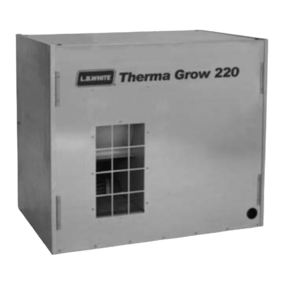
Greenhouse Heaters
Therma Grow
™
View this manual online at www.lbwhite.com
OUTPUT (Btuh)
220,000
FUEL
Available in either
L.P. Gas Vapor
Withdrawal or
Natural Gas
Configurations.
150-27595 REV.B
Advertisement
Table of Contents

Subscribe to Our Youtube Channel
Related Manuals for L.B. White Therma Grow 120NG


Summary of Contents for L.B. White Therma Grow 120NG
- Page 1 *Requires an app like QR Droid for Android or QR Reader for iPhone. We, at L.B. White, thank you for your confidence in our products and welcome any suggestions or comments you may have...call us, toll-free, at (800) 345-7200.
- Page 3 WARNING Proper gas supply pressure must be provided to the inlet of the heater. Refer to dataplate for proper gas supply pressure. Gas pressure in excess of the maximum inlet pressure specified at the heater inlet can cause fires or explosions. Fires or explosions can lead to serious injury, death, building damage, or loss of plant life.
-
Page 4: Table Of Contents
This manual will instruct you in the operation and care of your unit. Have your qualified installer review this manual The L.B. White Co., Inc. has a policy of continuous product with you so that you fully understand the heater and how it improvement. -
Page 5: Heater Specifications
Heater Specifications Model HW220 SPECIFICATIONS Propane Natural Maximum Input (BTUH) 220,000 550 CFM EXHAUST FAN Indoor Mounting Air Exchange Requirements SHUTTERED AIR INLET 120 sq. in. Outdoor Mounting Air SHUTTERED 220 sq. in. Exchange Requirements EXHAUST OUTLET Inlet Gas Supply MAX. -
Page 6: Safety Precautions
Refer to the specification section and installation quarters. instructions of the heater’s Owner’s Manual, heater dataplate, or contact the L.B. White Company to Do not use in areas without proper air exchange. See determine air exchange requirements of the heater. - Page 7 All GreenGro 2. All installations and applications of L.B. White heaters heaters, regardless of voltage, must be properly must meet all relevant local, state and national connected to a grounded electrical supply.
-
Page 8: Installation Instructions
An exhaust shuttered louver of at least 64 sq. in. follows: area. WARNING 1. Read all safety precautions and follow L.B. White Fire and Explosion Hazard recommendations when installing this heater. If Do not use open flame (matches, torches, candles, during the installation or relocating of heater, you etc.) in checking for gas leaks. -
Page 9: Air Discharge Diverter Duct
Do not use the heater in an L.P. gas liquid withdrawal system or application. If you are in doubt, contact the L.B. White Co., Inc. AIR DISCHARGE DIVERTER DUCT Part Number 25977 (Accessory) 1. -
Page 10: Air Inlet
INDOOR VENTILATION REQUIREMENTS This heater requires a properly sized motorized air inlet shutter, Side View flexible duct, and exhaust fan. All items must be installed when the heater is located within the greenhouse. These components, along with specific instructions, are provided HEATER in the indoor ventilation kit, part number 25985. -
Page 11: Exhaust Fan
Exhaust Fan FIG. 5 The exhaust fan must be located at an upper area of the EXHAUST FAN IN UPPER AREA OF end wall opposite from the heater, preferably in an area GREENHOUSE higher than the heater’s discharge. See Fig. 5. The fan does not need to be directly in line to the heater. -
Page 12: Sediment Trap Assembly Instructions
SEDIMENT TRAP ASSEMBLY Assemble the tee, nipples and cap together and tighten FIG. 8 securely. See Fig. 8. The sediment trap assembly must always be mounted in a vertical position. Make sure pipe NIPPLE thread compound that is resistant to both L.P. gas and HOSE ADAPTER natural gas is used in making all connections. -
Page 13: Start-Up Instructions
Start-Up Instructions Follow steps 1 - 6 on initial start-up after heater installation control box. A constant light from the LED is an by a qualified gas heater service person. For normal start- indicator that the heater is functioning correctly. up, simply turn thermostat above room temperature. -
Page 14: Cleaning Instructions
L.B. White Co., Inc. Dataplates, start- up and shut-down instructions and warnings are 4. Regulators can wear out and function improperly. -
Page 15: Service Instructions
Service Instructions GENERAL 4. The thermostat, and high limt switch can be tested by WARNING jumpering the suspect part out of the electrical Burn Hazard circuit.: Heater surfaces are hot for a period of time after the -- Reconnect the electrical supply and open fuel heater has been shut down. -
Page 16: Air Proving Switch
AIR PROVING SWITCH 1. Remove two sheet metal screws holding air proving FIG. 12 NUTS switch assembly to blower housing. Remove assembly by turning switch assembly 90 degrees so PADDLE the switch paddle can be pulled through oblong hole on side of fan housing. See Fig. 12. Disconnect the leads from the air proving switch. -
Page 17: Gas Pressure Checks
Gas Pressure Checks 2. Securely connect a pressure gauge to each pressure WARNING tap. Do not disassemble the gas control valve. 3. Open the fuel supply valves to the heater and reconnect the heater electrical supply. Do not attempt to replace any components of the gas control valve. -
Page 18: Igniter And Flame Sensor
IGNITER 1. Disconnect the plastic male and female plugs located 4. Slide the igniter shield over the igniter so hole in at the end of the igniter leads. See Fig. 16 shield aligns with hole in igniter and bracket. 2. Loosen the screw securing the igniter shield and the Handle the igniter by its ceramic base, or by its leads. -
Page 19: Troubleshooting Instructions
Troubleshooting Instructions READ THIS ENTIRE SECTION BEFORE BEGINNING TO OPERATION SEQUENCE: -- Line voltage is sent to motor relay and transformer WARNING -- Terminal at transformer branches off line voltage to terminal L1 on ignition control. This heater can start at any time. -- Transformer reduces line voltage to 24 VAC. -
Page 25: Electrical Connection And Ladder Diagram
Electrical Connection and Ladder Diagram 115 Volt Supply... -
Page 26: 230 Volt Supply
230 Volt Supply... -
Page 27: Heater Component Function
Heater Component Function Air Proving Switch Hot Surface Igniter Safety device used to insure that the proper air flow is being Ignition device used on automatic ignition control systems. achieved before the gas valve is opened. Ignites gas by surface temperature rather than spark or flame. -
Page 28: Parts Identification (Parts List & Schematic)
Parts Identification PARTS SCHEMATIC... - Page 29 Parts Identification PARTS LIST Item Description Part Number Regulator LP Gas 06553 Natural Gas 24414 Valve, Manual Shut Off with Nipple 03399 Hose, 1/2 x 10 ft., Rigid x Swivel 20714 Adapter, Hose, 1/2 NPT x 1/2 NPS 25873 Kit, Sediment Trap 00815 Screws (2) 572502...
-
Page 30: Warranty Policy
L B. White. L.B. White Co., Inc. will at its option, repair or replace the defective part or heater, with a new part or heater, F.O.B., Onalaska, Wisconsin, USA.
Need help?
Do you have a question about the Therma Grow 120NG and is the answer not in the manual?
Questions and answers