Advertisement
P
P
TELEMOTIVE
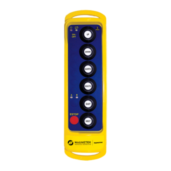
telePendant
TRANSMITTERS
telePendant programming is
found on page 24.
TCTX12P-0 Rev. E
R
O
G
R
A
M
M
I
R
O
G
R
A
M
M
I
N49 W13650 Campbell Drive
Menomonee Falls, WI 53051
Phone: 800-288-8178 Fax: 262-783-3510
Website:
www.magnetekmh.com
N
G
A
N
D
U
S
E
N
G
A
N
D
U
S
E
TM
R
A
D
I
O
R
A
D
I
O
C
O
N
T
R
O
C
O
N
T
R
E
Q
U
I
P
M
E
Q
U
I
P
M
R
S
M
A
N
U
A
L
R
S
M
A
N
U
A
L
L
O
L
E
N
T
E
N
T
11/11/2014
Advertisement

Related Manuals for Magnetek Telemotive TelePendant


Summary of Contents for Magnetek Telemotive TelePendant
- Page 1 TELEMOTIVE telePendant TRANSMITTERS telePendant programming is found on page 24. N49 W13650 Campbell Drive Menomonee Falls, WI 53051 Phone: 800-288-8178 Fax: 262-783-3510 Website: www.magnetekmh.com TCTX12P-0 Rev. E 11/11/2014...
-
Page 2: Table Of Contents
Table of Contents Service Information ....................3 Radio Controlled Crane Safety ................4 General System Information ..................14 Operation........................16 Programming......................24 RCP Programming ....................43 Spare Parts ......................55... -
Page 3: Service Information
Brand telePendant transmitter. Magnetek has set a whole new standard in performance, dependability, and value with its unique new line of receivers. Without a doubt, our Telemotive telePendant transmitter is the ultimate solution for having precise, undeterred, and safe control of your material... - Page 4 Section 2 – Radio Controlled Safety 2-1. Warnings, Cautions and Notes. Through out this document WARNING, CAUTION and NOTE statements have been deliberately placed to highlight items critical to the protection of personnel and equipment. WARNING – A warning highlights an essential operating or maintenance procedure, practice, etc. which if not strictly observed, could result in injury or death of personnel, or long term physical hazards.
- Page 5 Section 2 – Radio Controlled Safety (Continued) 2-2. Critical Installation Considerations. WARNING ALL EQUIPMENT MUST HAVE A MAINLINE CONTACTOR INSTALLED AND ALL TRACKED CRANES AND SIMILAR EQUIPMENT MUST HAVE A BRAKE INSTALLED. FAILURE TO FOLLOW THIS WARNING COULD RESULT IN SERIOUS INJURY OR DEATH AND DAMAGE TO EQUIPMENT. WARNING ON ALL REMOTE CONTROLLED CRANES AN AUDIBLE AND/OR VISUAL WARNING MEANS MUST BE PROVIDED.
- Page 6 Section 2 – Radio Controlled Safety (Continued) 2-4. Persons Authorized To Operate Radio Controlled Cranes. Only properly trained persons designated by management should be permitted to operate radio-controlled cranes. Radio controlled cranes should not be operated by any person who cannot read or understand signs, notices and operating instructions that pertain to the crane.
- Page 7 Section 2 – Radio Controlled Safety (Continued) 2-6. Operating Area. Aisles between equipment, stock, etc., should be free of obstructions so the crane operator can move freely. These aisles should be a minimum of three feet (one meter) wide, or meet local regulations. Crane operators should always position themselves for the best view of the crane they are controlling.
- Page 8 Section 2 – Radio Controlled Safety (Continued) If any crane or hoist fails any of the above tests notify the supervisor and lock out and tag for repair. 2-8.2. General Rules for Operation. Consult the crane manufacturer, local and governmental regulations for complete rules of operation. In general the following rules apply to remotely controlled cranes: The limit switches should never be used as a regular stopping device.
- Page 9 Section 2 – Radio Controlled Safety (Continued) If the crane fails to respond properly, the crane operator should stop operation, turn the transmitter unit OFF and immediately report the condition to their supervisor. Outdoor cranes, which are subject to movement by wind, should be securely anchored when left unattended. If the crane is equipped with bridge brakes, the parking brake should be set immediately.
- Page 10 Section 2 – Radio Controlled Safety (Continued) All tools and equipment should be moved onto the crane by the use of hand lines. The tools and equipment should be adequately secured to the hand lines. If it is necessary to have the crane control circuits energized, all power circuits for crane movement must be opened prior to energizing the control circuits.
- Page 11 Do not dispose of a battery pack in fire; it may explode. Do not attempt to open the battery pack. Do not short circuit battery. Do not attempt to use a battery that is leaking, swollen or corroded. For intrinsically safe environments only use specified Magnetek Telemotive intrinsically safe batteries.
- Page 12 For those transmitters equipped with battery chargers, please familiarize all users with the instructions of the charger before attempting to use. Use only Magnetek Telemotive approved chargers for the appropriate battery pack. Do not attempt to charge non-rechargeable battery packs.
- Page 13 Section 2 – Radio Controlled Safety (Continued) FCC Interference Statement (Part 15.105 (b)) This equipment has been tested and found to comply with the limits for a Class B digital device pursuant to Part 15 of the FCC Rules. These limits are designed to provide reasonable protection against harmful interference in a residential installation.
-
Page 14: General System Information
Section 3 – General System Information 3-1. General System Information. The Telemotive Radio Control System (system) provides remote control of overhead cranes using radio signals. The system consists of a hand held portable battery operated transmitter unit and a fixed station receiver unit. A unique 16-bit code (Access Code) for each system is preset in every transmitter and receiver. - Page 15 Section 3 – General System Information (Continued) 3-4. Transmitter Specifications. Transmitter housing: NEMA 4. Operating Temperature: –22° F to +158° F (-30º C to +70º C) ambient. Humidity: up to 95 % (non-condensing). Typical Operating Range: 200 feet (70 meters). 3-5.
-
Page 16: Operation
Section 4 – Operation ON/OFF Low Battery Indicators & Motor 1 Dir 1 AUX 1 Dir 2 AUX 2 AUX 3 Motor 2 AUX 4 Dir 1 AUX 5 Dir 2 AUX 6 Motor 3 Auxiliary Dir 1 Controls Dir 2 E-STOP Programmable Motor Control and Select Indicators... -
Page 17: Operation
Section 4 – Operation (Continued) Motor 1 Dir 2, DOWN – Selects hoist movement in the DOWN direction speed one (first switch position), speed two (second switch position). or speed three (third switch position if so equipped). Motor 2 Dir 1, NORTH or EAST – Selects the appropriate direction of the bridge or trolley (depending how unit is wired at installation) speed one (first switch position), speed two (second switch position), or speed three (third switch position if so equipped). - Page 18 Section 4 – Operation (Continued) 4-3. Low Battery Indication. In the telePendant transmitter there is a separate low battery indicator located to the right of the ON/OFF indicator. This is a yellow LED that turns ON solid when it is time to replace the batteries. See Section 4-6. Battery Replacement for battery replacement.
- Page 19 Section 4 – Operation (Continued) WARNING IN AN EMERGENCY HIT “E-STOP” TO STOP ALL CRANE MOVEMENT. WHEN EMERGENCY HAS CLEARED TURN THE TRANSMITTER OFF THEN ON AGAIN TO RESUME NORMAL OPERATION. FAILURE TO FOLLOW THIS WARNING COULD RESULT IN SERIOUS INJURY OR DEATH AND DAMAGE TO EQUIPMENT.
- Page 20 Section 4 – Operation (Continued) telePendant Bank Select (Normally Password Protected). This feature is like having four completely different transmitters in one unit. Up to four banks (operational configurations) are possible. A fifth bank is reserved for programming; this Bank is not password protected. A Bank is a specific configuration of user-defined parameters including: System type Frequency...
- Page 21 Section 4 – Operation (Continued) It is not necessary to program all four Banks; if an un-programmed or turned “off” Bank is selected, the ON/OFF indicator will remain ON continuously, the transmitter will send no commands, and it will turn itself off shortly.
- Page 22 Section 4 – Operation (Continued) telePendant Time-Out-Timer Function. The transmitter has a time-out timer and the default condition is 15 minutes. Upon timing out the transmitter will send an OFF command to the receiver if Auto Turn Off is active. The transmitter time-out- timer function is programmable in minute increments to up to and including 15 minutes.
- Page 23 Section 4 – Operation (Continued) For a battery carrier with two “AA” cells, replace the two “AA” cell batteries with new batteries, noting the polarity for “AA” cells marked on the holder. (Best life can be obtained if the two “AA” batteries used are new, a good quality alkaline type, both cells of the same type and from the same manufacturer).
-
Page 24: Programming
Section 5 – Programming 5-1. Access Codes. telePendant Membrane 10K Pendant Transmitter Transmitter Transmitter Receiver access code Indicates switch in OFF position TR12 Receiver Figure 5-1. Access Code Setting. (A dot on a switch position or a “1” in the label is an indication that the respective switch position should be ON). - Page 25 Section 5 – Programming (Continued) 5-1.2. Changing Transmitter Access Codes. 5-1.2.1. telePendant Access Code Programming. For detailed instructions on setting parameters including access codes see Section 5-3.2. telePendant Programming. WARNING AFTER CHANGING THE ACCESS CODES ON THE TRANSMITTER, TEST THE UNIT BY TURNING IT ON AND OFF NEAR THE APPROPRIATE RECEIVER.
- Page 26 Section 5 – Programming (Continued) 5-2. Multibox. Multibox Operation. (Optional; for receivers with Multibox option only). Do not use on inteleSmart Receivers. Use Group Code feature, see inteleSmart Receiver Manual. WARNING IF YOUR RECEIVER WAS NOT ORDERED WITH MULTIBOX DO NOT ATTEMPT TO PROGRAM MULTIBOX IN THE FIELD.
- Page 27 Section 5 – Programming (Continued) 5-3. Programming. 5-3.1. Transmitter Programming Options. The following parameters are programmable in the transmitter: Switch Position – Hoist, Trolley Etc. Timer-out-timer operation. Modes – Single speed switch grouping. Crane configuration - Tandem disable – Eliminates “both” Select invert –...
- Page 28 Section 5 – Programming (Continued) After loading the telePendant program the first screen is the initial setup screen. Transmitter Programmer Tx Type 2 SPD telePendant Use bank password 1 SPD telePilot 2 SPD telePilot First press Button 6 2 SPD telePendant Second press Button 5 3 SPD 10K Pendant...
- Page 29 Section 5 – Programming (Continued) WARNING THIS PASSWORD FUNCTION IS NOT TO BE USED AS A SECURITY DEVICE. THE PURPOSE OF THIS FUNCTION IS TO PREVENT ACCIDENTAL BANK SWITCHING. THE BEST FORM OF SECURITY IS ALWAYS TO LOCKUP THE TRANSMITTER WHEN NOT IN SERVICE. FAILURE TO FOLLOW THIS WARNING COULD RESULT IN SERIOUS INJURY OR DEATH AND DAMAGE TO EQUIPMENT.
- Page 30 Section 5 – Programming (Continued) Setup Bank Programming Screen. After seleting a Bank, the number of the Bank will appear at the top of the screen. The respective screens appear as shown below (the 2-Speed screen is shown first): Setup Bank # System Freq AK01...
- Page 31 Section 5 – Programming (Continued) G. Enter the Access Code (Must be inputted for system to work): Screen switch operation. The screen switches are labeled from left to right “A”, and “B”. They are numbered from left to right 1 to 8. The darkened rectangle to the bottom is “OFF”...
- Page 32 Section 5 – Programming (Continued) H. Multibox (Optional, skip if you do not wish to use the Multibox feature): Do not use on inteleSmart Receivers. Use Group Code feature see inteleSmart Receiver Manual. See Section 5-2. Multibox for details on Multibox programming. If your current receiver does not have Multibox do not attempt to use this function.
- Page 33 Section 5 – Programming (Continued) L. Go to the appropriate Section for your system. 5-3.3 2-Speed telePendant, Page 33. 5-3.4 3-Speed telePendant, Page 36. 5-3.5 3-Speed 10K Pendant, Page 38. 2-Speed telePendant Programming. 5-3.3. NOTE IF REPLACING A MEMBRANE OR PENDANT TRANSMITTER, YOU CAN COPY THE SWITCH SETTINGS ON THE EXISTING TRANSMITTER.
- Page 34 Section 5 – Programming (Continued) N. Main/Aux Menu for controlling the “Programmable Motor Control and Select Push Button”. This menu shows only if no Special Crane Configurations are selected (Switch 3 positions 5-7). This programming redefines the function of the button just above the E-STOP. (For a three motor crane use “Aux”, for standard four motor use “Motor ”, and for Select function use Select).
- Page 35 Section 5 – Programming (Continued) This completes the 10K 2-speed programming; when completed with the above, tap “Save”. Save will take you back to the Initial start screen. At this point select another Bank to program or go to Section 5-4. Saving, Downloading, Reading the Programs and Other PDA Functions on page 40.
- Page 36 Section 5 – Programming (Continued) 3-Speed telePendant Programming . 5-3.4. M. Motor Menu for controlling the “Programmable Motor Control” Push Button. (For a three motor crane use “3”, for standard five or four motor use “5 “). For three motor system this push button is nonfunctional (Motor “3”). This configuration is typically used with the inteleSmart 16 output Receiver.
- Page 37 Section 5 – Programming (Continued) Setup Bank # Freq AK01 Receiver access code RX Setting Multibox Active ESTOP Timer Motor Tandem off Save Cancel NOTE TO PROGRAM OR READ DATA FROM THE telePendant, THE TRANSMITTER MUST BE TURNED ON AND IN BANK FIVE (5).
- Page 38 Section 5 – Programming (Continued) 3-Speed 10KPendant Programming. 5-3.5. N. Motor Menu for controlling the “Programmable Motor Control and Select” Push Button. (For a three motor crane use “3”; for standard five motor use “5”, for Select function use Select). For three motor system this push button is nonfunctional (Motor “3”).
- Page 39 Section 5 – Programming (Continued) Setup Bank # Freq AK01 Receiver access code RX Setting Multibox Active ESTOP Aux Trolley off Timer Motor Tandem off Save Cancel NOTE TO PROGRAM OR READ DATA FROM THE telePendant, THE TRANSMITTER MUST BE TURNED ON AND IN BANK FIVE (5).
- Page 40 Section 5 – Programming (Continued) 5-4. Saving, Downloading, Reading The Programs and Other PDA Functions. NOTE TO PROGRAM OR READ DATA FROM THE telePendant, THE TRANSMITTER MUST BE TURNED ON AND IN BANK FIVE (5). Saving the Programming File. With the initial telePendant screen displayed, tap in the lower left corner of your PDA, the title bar at the top of the screen will show a menu or tap on the word “telePendant”.
- Page 41 Section 5 – Programming (Continued) 3. Line up the PDA’s infrared port with the transmitter’s infrared port (remove battery door on the back and pull battery pack back to expose the telePendant’s infrared port. See figure below: telePendant Infrared Port Access). Battery pack telePendant Infrared Port Access.
- Page 42 Section 5 – Programming (Continued) Reading the telePendant History. To read Service information from the telePendant Transmitter: 1. Line up the PDA’s infrared port and go to bank 5 as in steps 1 to 3 above, with the transmitter ON. Select “Admin”...
-
Page 43: Rcp Programming
Section 6 – RCP Programming 6-1. Access Codes. Membrane telePendant 10K Pendant Transmitter Transmitter Transmitter Receiver access code Indicates switch in OFF position TR12 Receiver Figure 6-1. Access Code Setting. (A dot on a switch position or a “1” in the label is an indication that the respective switch position should be ON). - Page 44 Section 6 – RCP Programming (Continued) 6-2. Changing Transmitter Access Codes. 6-2.1.1. telePendant Access Code Programming. For detailed instructions on setting parameters including access codes see Section 5-3.2. telePendant Programming. WARNING AFTER CHANGING THE ACCESS CODES ON THE TRANSMITTER, TEST THE UNIT BY TURNING IT ON AND OFF NEAR THE APPROPRIATE RECEIVER.
- Page 45 Magnetek distributor. Magnetek RCP software is user friendly and is intended to provide plain language descriptions of all transmitter functions and options. Help is provided for each function at the bottom of the RCP screen. The RCP software allows you to select frequency, access code, time-out-timer settings, switch arrangement and crane configuration as in other Telemotive transmitter products.
- Page 46 Section 6 – RCP Programming (Continued) Install the RCP software. After installation of the RCP Software, double-click the RCP icon found on the desktop to launch the program. This will prompt you to enter an activation key. If an activation key is not entered at this time, the software can only be used 10 times before locking the user out.
- Page 47 Section 6 – RCP Programming (Continued) Click on New Project or Open Project Select new project if you are creating a new program file. Select open project if you want to retrieve an existing program file. A list of recent projects will appear under Open Project. Clicking on one of these will open that project.
- Page 48 Section 6 – RCP Programming (Continued) Common settings. The telePendant transmitter has four configurable “Banks” available. Each bank is a complete operational configuration consisting of frequency, access code and other transmitter parameters. These banks give the capability to operate up to four different cranes using one transmitter, and they can be used as possible options for crane select.
- Page 49 Section 6 – RCP Programming (Continued) The Bank password can be disabled during initial programming by the RCP software. To disable password protection, uncheck the box next to the phase “Use bank password”. Disabling the Bank password is not recommended unless the operator has access and visibility to all possible cranes controlled. WARNING DISABLING THE PASSWORD FUNCTION PUTS THE SYSTEM IN ACTIVE BANK SELECT.
- Page 50 Section 6 – RCP Programming (Continued) This will open the bank programming screen. NOTE IF YOU HAVE AN INTELESMART RECEIVER, FREQUENCY AND ACCESS CODES CAN EASILY BE DOWN LOADED DIRECTLY INTO THE RCP SOFTWARE. Downloading Parameters from an inteleSmart receiver. Select the Bank you wish to program, and then cycle the power to the inteleSmart receiver.
- Page 51 Section 6 – RCP Programming (Continued) Enter the Access Code (must be set for system to work): Screen switch operation. The screen switches are labeled from left to right “A”, and “B”. They are numbered from left to right 1 to 8. The black rectangle to the bottom is “OFF”...
- Page 52 Section 6 – RCP Programming (Continued) Multibox (Optional; skip if you do not wish to use the Multibox feature): Do not use on inteleSmart Receivers. Use Group Code feature see inteleSmart Receiver Manual. See Section 5-2. Multibox for details on Multibox programming. If your current receiver does not have Multibox do not attempt to use this function.
- Page 53 Section 6 – RCP Programming (Continued) Time-out-timer Disable (normally not checked). Disables the transmitter time-out-timer if checked. If the time-out-timer is active, the length of time for time out can be selected for numbers of minutes till shut down. The minutes are selectable in one-minute steps from 1 to 10 and five minutes steps up to an hour.
- Page 54 Section 6 – RCP Programming (Continued) Sending a Program to the telePendant. WARNING AFTER EVERY PROGRAMMING OF THE TRANSMITTER, TEST THE UNIT BY TURNING IT ON AND OFF NEAR THE APPROPRIATE RECEIVER. IF THE RECEIVER DOES NOT RESPOND, DO NOT ACTIVATE A FUNCTION BUTTON! THE TRANSMITTER MAY HAVE INCORRECT PROGRAMMING, WHICH COULD MOVE ANOTHER CRANE.
- Page 55 Section 6 – RCP Programming (Continued) Error Statements and Codes. Tx Type Mismatch; if while attempting to program a telePendant you receive an error code such as “Error AAAB” you have selected a different style transmitter in the PDA than you are attempting to program. Most common cause is trying to program a 2-speed telePendant with 3-speed selected or visa versa.
-
Page 56: Spare Parts
Section 7 – Spare Parts telePendant TRANSMITTER PART NUMBER DESCRIPTION Call MAIN CIRCUIT BOARD 2- or 3-SPEED (Please contact Telemotive with Job Number to assure exact replacement). H1212-0 #4 x 3/8” SELF TAPPING SCREWS, PC BOARD MOUNTING (2) H1147-0 NEOPRENE WASHER, PC BOARD MOUNTING (4) H1976-0 STEEL FLAT WASHER, PC BOARD MOUNTING (2) N10705-1...
Need help?
Do you have a question about the Telemotive TelePendant and is the answer not in the manual?
Questions and answers