
Related Manuals for Magnetek Flex Pro


Summary of Contents for Magnetek Flex Pro
- Page 1 Flex Pro Transmitter Radio Control Equipment Instruction Manual Part Number: 198-50003 R5 June 2013 ©Copyright 2013 Magnetek Material Handling...
-
Page 2: Table Of Contents
5.3 STATUS LIGHTS INDICATORS & WARNINGS ................19 5.4 PUSH BUTTON ERROR TABLE ...................... 19 5.5 TROUBLE SHOOTING TIPS ......................20 6.0 DECLARATION OF CONFORMITY ..................... 21 Flex Pro Transmitter Radio Control Equipment Instruction Manual June 2013 Page 2 of 21... -
Page 3: Service Contact Information
Service Contact Information Thank you for your purchase of Magnetek’s Enrange™ Flex Pro radio remote control system. Without a doubt, our Flex Pro system is the ultimate solution for providing precise, undeterred, and safe control of your material. If your product ever needs modification or service, please contact one of our representatives at the following locations: U.S. -
Page 4: Preface And Safety
It is the responsibility of the owners, users and operators of the Magnetek Products to know, understand and follow all of these requirements. It is the responsibility of the employer to make its employees aware of all of the above listed requirements and to make certain that all operators are properly trained. -
Page 5: Introduction
Full compliance – All systems are fully compliant with the FCC Part-15 Rules, European Directives (Safety, EMC, R&TTE, and Machinery), and Industry Canada Specifications (IC). Flex Pro Transmitter Radio Control Equipment Instruction Manual June 2013 Page 5 of 21... -
Page 6: Radio And Safety
It is important to read all of the safety information contained in this section before installing or operating the Radio Control System. Flex Pro Transmitter Radio Control Equipment Instruction Manual June 2013 Page 6 of 21... -
Page 7: Critical Installation Considerations
The following recommendations have been included to indicate how careful and thoughtful actions may prevent injuries, damage to equipment, or even save a life. Flex Pro Transmitter Radio Control Equipment Instruction Manual June 2013 Page 7 of 21... -
Page 8: Persons Authorized To Operate Radio Controlled Cranes
operate the material handling equipment if the direction of travel or function engaged does not agree with what is indicated on the controller Flex Pro Transmitter Radio Control Equipment Instruction Manual June 2013 Page 8 of 21... -
Page 9: Transmitter Unit
IMMEDIATELY BE TAKEN OUT OF SERVICE AND BE REPORTED TO THE SUPERVISOR. DAMAGED AND INOPERABLE RADIO CONTROLLER EQUIPMENT SHOULD BE RETURNED TO MAGNETEK FOR EVALUATION AND REPAIR. FAILURE TO FOLLOW THIS WARNING COULD RESULT IN SERIOUS INJURY OR DEATH AND DAMAGE TO EQUIPMENT. -
Page 10: Batteries
Do not attempt to open the battery pack. Do not short circuit the battery. For intrinsically safe environments only use specified Magnetek Telemotive intrinsically safe batteries. Keep the battery pack environment cool during charging operation and storage (i.e., not in direct sunlight or close to a heating source). -
Page 11: Specific System Warnings
2.11 SPECIFIC SYSTEM WARNINGS Below are some specific operating safety tips that should be strictly followed when operating a Flex Pro system: 1. Check the Status LED on the transmitter for any signs of low battery power (refer to page 19). -
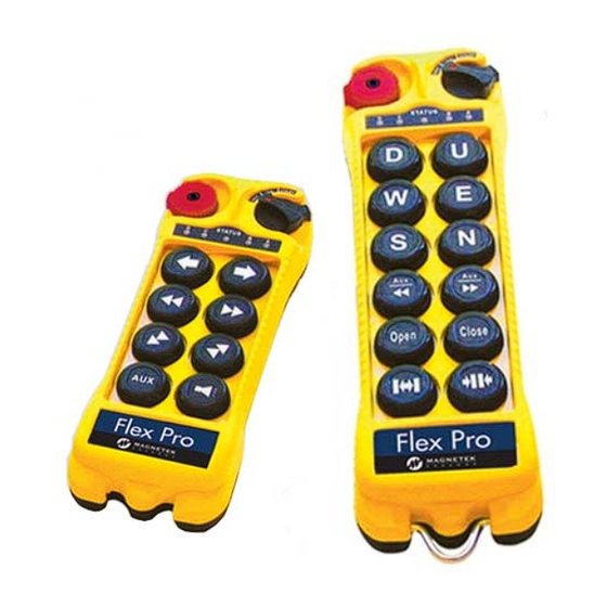
Page 12: General Transmitter Information
Push Button #4 Push Button #11 Push Button #5 Push Button #12 NOTE: Push Buttons #9-#12 are not present on the Flex Pro 8 Module Flex Pro Transmitter Radio Control Equipment Instruction Manual June 2013 Page 12 of 21... -
Page 13: Internal Illustration (Pro 12 Configuration)
(Fig. 04) Encoder Board I-CHIP Aerial Antenna Dip-Switch Transmitting Module Battery Contact Mechanism Status LED Display Function LED Displays NOTE: Flex Pro 8 Module will differ slightly Flex Pro Transmitter Radio Control Equipment Instruction Manual June 2013 Page 13 of 21... -
Page 14: Types Of Buttons
3.3 TYPES OF BUTTONS The buttons used on the Flex Pro are fully proportional, stepless push buttons with an output that varies 0-100% (based on how far the button is depressed). It is possible to model the stepless buttons as an On/Off momentary switch, On/Off latched switch, 2 Speed button, or a 3 Speed button. -
Page 15: Dip-Switch Settings
Bottom slot → “0” The above dip-switch setting “1 0 0 1 0” corresponds to “channel 19” in the system channels table (on page 16). Flex Pro Transmitter Radio Control Equipment Instruction Manual June 2013 Page 15 of 21... -
Page 16: Inactivity Time-Out Timer
Bits 6 and 7 on the dip-switch allows the user to define a time after which, if no buttons on the transmitter are pressed, the Flex Pro will send an OFF command to the receiver and power down. To restart, the user must turn the On/Off/Start switch to the Off position, then back to On again to resume operation. -
Page 17: Operating Procedure
“Start” position for up to 2 seconds. This will activate the receiver E-Stop. Thereafter, the same “Start” position will become an auxiliary function with momentary contact. (Fig. 13) Flex Pro Transmitter Radio Control Equipment Instruction Manual June 2013 Page 17 of 21... -
Page 18: Changing Transmitter Batteries
After changing the batteries also make sure that all screws are tightened to avoid water, moisture, dirt, grease, or other liquid penetration. ↓ (Fig. 14) (Fig. 15) Flex Pro Transmitter Radio Control Equipment Instruction Manual June 2013 Page 18 of 21... -
Page 19: Status Lights Indicators & Warnings
Solid Red ESTOP deactivated. Voltage goes below 1.9V at initial power on - transmitter Solid Red power shuts off. 5.4 PUSH BUTTON ERROR TABLE Push Button Flex Pro Transmitter Radio Control Equipment Instruction Manual June 2013 Page 19 of 21... -
Page 20: Trouble Shooting Tips
Receiver Access Code. Make sure that the startup procedure is initiated System out of range within 100 meters (300 feet) from the receiver location. Flex Pro Transmitter Radio Control Equipment Instruction Manual June 2013 Page 20 of 21... -
Page 21: Declaration Of Conformity
6.0 DECLARATION OF CONFORMITY June 2013 Page 21 of 21 Flex Pro Transmitter Radio Control Equipment Instruction Manual... - Page 22 N49 W13650 Campbell Drive Menomonee Falls, WI 53051 Phone: 800-288-8178 Fax: 800-298-3503 Website: www.telemotive.com A10723-0 BT111-1 Lithium Ion (Li-Ion) Battery Lithium Ion Battery Charger for Note: All new rechargeable battery packs must be charged before usage. GENERAL BATTERY AND CHARGER PRECAUTIONS Use of this device is intended for charging BT111-1 (Lithium Ion) rechargeable batteries only.
- Page 23 CHARGING INSTRUCTIONS Connect barrel plug end on the AC adapter into the socket at the side of this charger unit and the AC plug into any standard AC wall outlet. The GREEN LED light on the charger will go on to indicate the charger is ready for use. Insert your Li-Ion battery on the charging plate making sure it is placed on correctly to match the arrow on the charger with the arrow on the battery.
Need help?
Do you have a question about the Flex Pro and is the answer not in the manual?
Questions and answers